Cutting Sections
A cutting section [or cutting plane], is an invisible, infinite plane that cuts away part of a scene. These cut-away views are used to show inner pieces of an assembly or expose detail that would otherwise be obscured. A cutting plane is considered geometry, thus, it is affected by any modelling matrices present of its parent segment. A scene can contain more than one cutting plane - geometry is removed if it is cut away by any cutting plane. In Visualize, a plane is defined using the coefficients of the geometric equation of a plane. The plane equation is:
ax + by + cx + d = 0
The plane itself is all points (x, y, z) in space that satisfy this equation. The part of the scene that is cut away is all points (x, y, z) that satisfy the following inequality:
ax + by + cz + d > 0
When visualizing how the plane equation defines a plane in space, simply imagine the coefficients a, b, and c as components of a vector originating at the origin. The plane will be perpendicular to that vector. The coefficient d is the distance from the origin along the vector that the plane will be offset. For any plane, there is an infinite number of values for (a, b, c, d) that define it.
So, let’s say you have a piece of geometry that you would like to cut. For this example, a simple sphere with center at the origin and radius 0.75 units is shown. The top portion of the sphere is cut away to make the inside visible. The following code snippet will demonstrate the effect. Note that the cut edges, if desired, also need to be colored and enabled as they are not visible by default. Thus, to insert a cutting section in Visualize, you could use the following code:
    // cut edges enabled
    mySegmentKey.GetVisibilityControl().SetCutEdges(true);

    // cut edges set to red
    mySegmentKey.GetMaterialMappingControl().SetCutEdgeColor(HPS::RGBAColor(1, 0, 0));

    // cut plane is 0.42 units from the origin
    mySegmentKey.InsertCuttingSection(HPS::Plane(0, 1, 0, -0.42f));
// cut edges enabled
mySegmentKey.GetVisibilityControl().SetCutEdges(true);

// cut edges set to red
mySegmentKey.GetMaterialMappingControl().SetCutEdgeColor(new HPS.RGBAColor(1, 0, 0));

// cut plane is 0.42 units from the origin
mySegmentKey.InsertCuttingSection(new Plane(0, 1, 0, -0.42f));
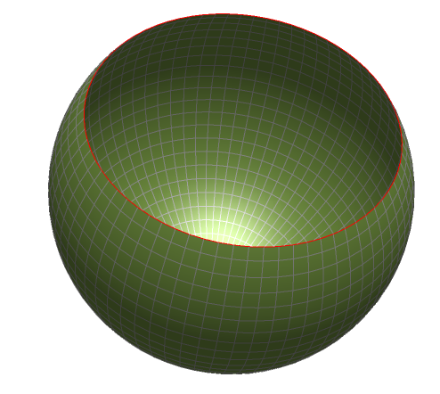
A sphere cut by a cutting plane. The scene has been rotated for clarity.
Sometimes it is useful to be able to see the cutting plane itself. In that case, use a HPS::CuttingSectionKit to set the visualization parameters:
    HPS::CuttingSectionKit csk;
    csk.SetVisualization(HPS::CuttingSection::Mode::Square, HPS::RGBAColor(0.25f, 0.25f, 0.25f, 0.25f));
    csk.SetPlanes(HPS::Plane(0, 1, 0, -0.42f));

    mySegmentKey.InsertCuttingSection(csk);
HPS.CuttingSectionKit csk = new HPS.CuttingSectionKit();
csk.SetVisualization(HPS.CuttingSection.Mode.Square, new HPS.RGBAColor(0.25f, 0.25f, 0.25f, 0.25f));
csk.SetPlanes(new HPS.Plane(0, 1, 0, -0.42f));

mySegmentKey.InsertCuttingSection(csk);
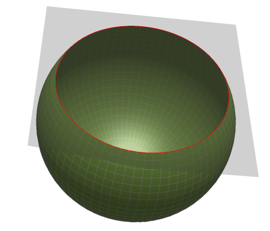
The cutting plane is made visible
Alternatively, HOOPS Visualize can draw a cutting section cap over the cut away region when the cut faces are made visible. Using the HPS::MaterialMappingControl, this cap can be assigned any type of material, just like any other geometry. In this case, it is set to a solid color:
    mySegmentKey.GetVisibilityControl().SetCutFaces(true); // make cut faces visible

    mySegmentKey.GetMaterialMappingControl().SetCutFaceColor(HPS::RGBAColor(0.5f, 0, 0));
mySegmentKey.GetVisibilityControl().SetCutFaces(true); // make cut faces visible

mySegmentKey.GetMaterialMappingControl().SetCutFaceColor(new HPS.RGBAColor(0.5f, 0, 0));
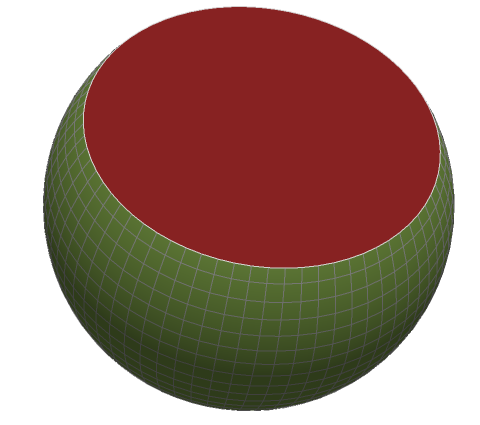
The capping geometry
To enable multiple cutting planes in the scene, simply pass an array of planes to SetPlanes:
    HPS::CuttingSectionKit csk;

    PlaneArray planeArray(2);
    planeArray[0] = HPS::Plane(0, 1, 0, -0.1f);
    planeArray[1] = HPS::Plane(-1, 0, 0, 0);
    csk.SetPlanes(planeArray);

    mySegmentKey.InsertCuttingSection(csk);
HPS.CuttingSectionKit csk = new HPS.CuttingSectionKit();

HPS.Plane[] planeArray = new Plane[2];
planeArray[0] = new Plane(0, 1, 0, -0.1f);
planeArray[1] = new Plane(-1, 0, 0, 0);
csk.SetPlanes(planeArray);

mySegmentKey.InsertCuttingSection(csk);
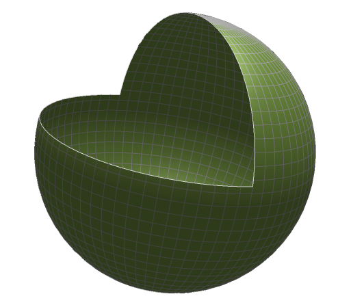
Multiple cutting planes produce a complex interior view
Setting the Cutting Section Level
The cutting section level setting makes a big difference in what is cut away by the cutting section. The level can be set locally or globally. A local cutting plane only cuts geometry in its segment or subsegments. Global cutting planes cut all geometry in the scene graph. The cutting level is controlled using the HPS::CuttingSectionAttributeControl.
    // set a local cutting section
    mySegmentKey.GetCuttingSectionAttributeControl().SetCuttingLevel(HPS::CuttingSection::CuttingLevel::Local);

    // set a global cutting section
    mySegmentKey.GetCuttingSectionAttributeControl().SetCuttingLevel(HPS::CuttingSection::CuttingLevel::Global);
// set a local cutting section
mySegmentKey.GetCuttingSectionAttributeControl().SetCuttingLevel(HPS.CuttingSection.CuttingLevel.Local);

// set a global cutting section
mySegmentKey.GetCuttingSectionAttributeControl().SetCuttingLevel(HPS.CuttingSection.CuttingLevel.Global);
Guidelines for Multiple Cutting Sections
If cutting sections are an integral part of your application, or you insert and remove them often, you may want to consider grouping your specific cutting section attributes into a HPS::CuttingSectionAttributeKit. Doing so saves you the trouble of applying the same attributes over and over because the attributes are saved in the kit. The kit is then applied to a segment whenever necessary.
    HPS::CuttingSectionAttributeKit csak;
    csak.SetCappingLevel(HPS::CuttingSection::CappingLevel::SegmentTree);
    csak.SetMaterialPreference(HPS::CuttingSection::MaterialPreference::Explicit);

    mySegmentKey.SetCuttingSectionAttribute(csak);
HPS.CuttingSectionAttributeKit csak = new HPS.CuttingSectionAttributeKit();
csak.SetCappingLevel(HPS.CuttingSection.CappingLevel.SegmentTree);
csak.SetMaterialPreference(HPS.CuttingSection.MaterialPreference.Explicit);

mySegmentKey.SetCuttingSectionAttribute(csak);
Extracting Cutting Plane Geometry
HOOPS Visualize offers you the ability to extract the capping geometry created by a cutting plane. The capping faces are delivered in the form of shells to a segment you specify. Edges are delivered as polylines.
Capping geometry extraction is specified using a HPS::CutGeometryGatheringOptionsKit. The kit allows you to specify the depth for which the cut geometry will be gathered, as well as the segment where the caps will be placed are the operation is complete.
The following code sample assumes the model has been loaded into a subsegment of the window key called “model”. The capping geometry is extracted to the “caps” subsegment. The actual gathering is done with a HPS::KeyPath. The key path must lead back to a window key.
    // enable visibility of cut geometry
    myWindowKey.GetVisibilityControl().SetCutGeometry(true);

    // set the cutting depth for cutting section
    myWindowKey.GetCuttingSectionAttributeControl()
        .SetCappingLevel(HPS::CuttingSection::CappingLevel::Segment)
        .SetCuttingLevel(HPS::CuttingSection::CuttingLevel::Global);

    // insert cutting section
    HPS::CuttingSectionKey cutterKey = myWindowKey.InsertCuttingSection(HPS::Plane(HPS::Vector(1, 0, 0)));

    // set gather depth
    HPS::CutGeometryGatheringOptionsKit opt;
    opt.SetLevel(CuttingSection::GatheringLevel::Segment);

    // build path to window
    HPS::KeyPath path;
    path.PushBack(myWindowKey);

    // put cut geometry into subsegment called "caps"
    path.GatherCutGeometry(myWindowKey.Subsegment("caps"), opt);

    // delete model to leave just the caps in place (optional)
    myWindowKey.Subsegment("model").Delete();
// enable visibility of cut geometry
myWindowKey.GetVisibilityControl().SetCutGeometry(true);

// set the cutting depth for cutting section
myWindowKey.GetCuttingSectionAttributeControl()
    .SetCappingLevel(HPS.CuttingSection.CappingLevel.Segment)
    .SetCuttingLevel(HPS.CuttingSection.CuttingLevel.Global);

// insert cutting section
HPS.CuttingSectionKey cutterKey = myWindowKey.InsertCuttingSection(new HPS.Plane(new HPS.Vector(1, 0, 0)));

// set gather depth
HPS.CutGeometryGatheringOptionsKit opt = new HPS.CutGeometryGatheringOptionsKit();
opt.SetLevel(HPS.CuttingSection.GatheringLevel.Segment);

//build path to window
HPS.KeyPath path = new HPS.KeyPath();
path.Append(myWindowKey);

// put cut geometry into subsegment called "caps"
ulong cap_count = path.GatherCutGeometry(myWindowKey.Subsegment("caps"), opt);

// delete model to leave just the caps in place (optional)
myWindowKey.Subsegment("model").Delete();
The result of this operation is shown below, as applied to the turbine model:
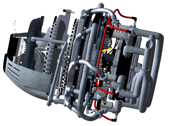
The turbine model
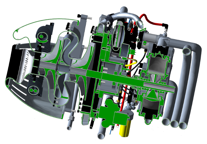
The turbine model sectioned by a cutting plane. Notice the cut faces.

After removing the model, only the capping geometry is left.
