You can open any of the supported files by selecting Open Workspace… on the File menu or
on the Standard toolbar. (See also The SpinFire Insight User Interface.)
Alternately, you can use the Library to set up connections to the folders you use most often, and make your selection(s) from there.
Note
SpinFire .3D Files
.3D files generated previous to SpinFire 10.0 are not supported by SpinFire Insight and may not open successfully.
Load only the assembly tree of the selected file. Supported for CATIA V4, CATIA V5, ProEngineer & Creo, UG/NX, and SolidWorks only.
If you open a shattered assembly with this command, Save Monolithic File… will appear on the File menu, thereby giving you the means to preserve the file links and save changes. (See Shattered Assemblies for more information.)
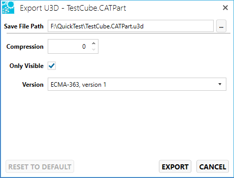
From the Menu bar, select File > Export, then select the CAD format to export to. Choose from 3D PDF, 3MF, ACIS, AutoCAD, glTF, HSF, IGES, JT, Parasolid, PRC, STEP, STL, U3D, and VRML.
Change the settings specific to the CAD format you are exporting to.
3MF format example:
Click Export.
Note
Be sure to examine the Save File Path field to specify the path and file name of the file.
Export to a Bitmap (.bmp), Enhanced Metafile (.emf), Exchangeable Image Format (.exif), Graphics Interchange Format (.gif), Joint Photographic Experts Group format (.jpeg), Portable Network Graphics image (.png), Tagged Image File Format (.tiff), or Windows Metafile (.wmf) file format.
Use the Copy to Clipboard button to copy the image to the clipboard.
To save a model view as an image file:
From the Menu bar, select File > Export to open the file formats flyout menu.
Click Image… to open the Export Image dialog box.
Enter the desired width and height of the image. If you want to keep the original image proportions, select the Keep Aspect Ratio checkbox. Or, if you prefer to choose from a list of preset dimensions, select an option from the Size Type drop-down menu.
Click the […] button to select the desired file location and format. The default format is bitmap (.bmp).
Enable Vectorized for a vectorized image.
Click Save, then EXPORT.
Note
When a 3D document is exported as an EMF, a black-and-white, hidden line vector representation of the scene is saved.
If the cross-section plane is enabled in a 3D document, you can save the section profile as an EMF by clicking Section Profile.
Export to a PDF. Use this command to create a print file of the active Workspace.
Note
Use the File > Export > 3D PDF command to take advantage of the Adobe Acrobat Pro Extended features.
To create a PDF for printing hardcopy:
From the Menu bar, select File > Export to open the file formats flyout menu.
Click Hardcopy… to open the Export Hardcopy dialog box.
Enter the desired width and height of the image. If you want to keep the original image proportions, select the Keep Aspect Ratio checkbox.
From the respective drop-down lists, select
Resolution - The greater the resolution, the larger the file
Size Type - Page sizes
Units - Preferred units of measurement
WYSIWYG - Select to include only what is displayed on the screen. Clear to print everything that will fit on the specified page size, even if not visible on the screen.
Click the […] button to navigate to the desired file location.
Create a parts list from the Workspace assembly. (See also Export Parts List.)
Note
A parts list is generated only for 3D documents. An active 3D workspace is required to initiate the command. If a 2D drawing or image document is active, the parts list generator is disabled.
To create an assembly parts list:
Select File > Export > Parts List.
In the Parts List dialog box, click the desired assembly or subassembly level, then
Choose to create a Flat Single-Level (default) or a Multi-Level list.
Select or clear the Include Hidden Parts and Apply Template checkboxes. (See Using the Templates Editor for information about using templates.)
Click Select Columns to select which columns of data to view and export.
Once you are satisfied with your list, you may choose to print it or save it as a text file. Click one of the following buttons:
Print… - Open the Windows Print dialog box.
Preview… - Review the list before printing.
Save - Save to one of the following file formats: text (*.txt), CSV (*.csv), XML (*.xml), Excel 97 (*.xls), and Excel 2007 (*.xlsx).
The Parts List dialog box (shown above) enables you to select which parts to include in your list.
In the Assembly pane, choose the assembly level for which you would like a list and then select a format:
Flat Single-Level - Displays a numbered list comprised of generic part names and quantities in the selected assembly level. If any part is included more than once in a particular level, the number of occurrences is included in the total count. (Flat Single-Level is the default selection.)
Multi-Level - Displays a hierarchical numbered list comprised of the assembly level name(s) and corresponding generic part name(s) and the total quantity of parts in each assembly level. The list clearly shows the relationship between assembly, sub-assemblies, and constituent components (as shown above).
You can also choose to include all parts in the assembly (Include Hidden Parts checkbox), and whether to use the default document template or a custom template when printing (Apply Template checkbox).
Export to an Initial Graphics Exchange Specification (IGES) (pronounced eye-jess) file format (refer to U.S. National Institute of Standards and Technology).
The Convert dialog window will detect the native CAD format and display the import options on the left side.
The right side shows a list of CAD formats (ACT3D, 3D PDF, 3MF, ACIS, glTF, HSF, IGES, JT, Parasolid, PRC, STEP, STL, U3D, VRML) where each are expandable to reveal the settings to save to.
Check the file format(s) to convert to.
Set the various settings.
Click Convert.
Go to the Library to view the status of the conversion(s).
Print the active Workspace document. You can select from the default SpinFire Insight print template or create a template of your own. (See Tools Menu Document Commands for more information.)
Select the desired printer and corresponding preferences as you would with any Windows document.
To print a document:
From the Menu bar, select File > Print Document… or click
in the Standard toolbar.
In the Print Options dialog box, select to use the default print template or a custom template (see Using the Templates Editor).
Click OK.
In the Windows Print dialog box, select the options you want and click Print.
Enables you to apply a print template and position your document on the page before printing. (See also Tools Menu Document Commands.)
To preview your document before printing:
From the Menu bar, select File > Print Preview… to see how your document will look on the printed page.
You can adjust your view to examine the document using the zoom, Zoom to Default Size, Fit to Width, or Fit to Page icons located in the upper-left of the display. These commands do not alter the way the document is printed.
If you want to use a print template (*.tpl), enter the filename in the Apply Template field. (You can also use the […] button to navigate to your template.) See Using the Templates Editor.
Enable Vectorized if you wish to print a vectorized image.
Adjust the scale of the image as it appears in the print preview and ultimately your print out by adjusting the scale control.
Click FIT MODEL TO PAGE for SpinFire Insight to fit the model on the page, moving the camera if necessary.
This automatically turns off the background, coordinate systems, axis triad, navigation cube, grid, ruler, and scale bar. These can be enabled in the More Image Settings controls.
Click FIT VIEW TO PAGE for SpinFire Insight to fit the current view of the model and fit it on the page. The camera does not move or change however the view may scale to fit the page.
This automatically turns off the background, coordinate systems, axis triad, navigation cube, grid, ruler, and scale bar. These can be enabled in the More Image Settings controls.
Turn off background color, notes, dimensions, coordinate systems, annotations, axis triad, navigation cube, grid, labels, and the scale bar via the More Image Settings.
Move or nudge the camera in any of eight directions by a configurable distance via the More Camera Settings.
Select Printer and set Printer Properties.
Set the orientation, paper size, and margin widths.
If the view is satisfactory, click the printer icon to open the Windows Print dialog box.
Note that you can toggle between portrait and landscape orientations.
Turn off header and footer information via the More Page Settings.
In the Windows Print dialog box, select the options you want and click Print.
Close all files and exit SpinFire Insight. You can also click X (Close) in the upper-right corner of the SpinFire Insight window.
Note
All documents are closed and the Workspace is cleared. Recently opened documents are listed on the Home page (see Home for an example).
Conversation saved
SPINNY BETA
Hello! I'm SPINNY
Your multilingual generative AI assistant for documentation. Ask me anything about SpinFire Insight in your own language, or choose a sample question below to start a conversation:
What is SpinFire Insight?
What are the latest release notes for SpinFire Insight?
How do I start evaluating SpinFire Insight?
How can I get assistance?
SPINNY may store conversations according to OpenAI's policy. Responses may not always be accurate.