Text
Like all other geometry, each text object is represented in the database by a key. Visualize has many different text attributes that are accessed through the key. Unlike other geometry, text attributes can be set at either the object or segment level. If any text attribute is set at both the segment level and on the TextKey, the TextKey setting takes precedence. Text is configured by a HPS::TextKit and inserted using HPS::SegmentKey::InsertText:
    HPS::TextKit textKit;

    textKit.SetPosition(Point(0, 0, 0));
    textKit.SetFont("verdana");
    textKit.SetText("TECH SOFT 3D");
    textKit.SetColor(HPS::RGBColor(1, 0.5, 0));
    textKit.SetSize(40, HPS::Text::SizeUnits::Pixels);
    textKit.SetAlignment(HPS::Text::Alignment::Center); // relative to insertion point

    mySegmentKey.InsertText(textKit);
HPS.TextKit textKit = new HPS.TextKit();

textKit.SetPosition(new HPS.Point(0, 0, 0));
textKit.SetFont("verdana");
textKit.SetText("TECH SOFT 3D");
textKit.SetColor(new HPS.RGBAColor(1, 0.5f, 0));
textKit.SetSize(40, HPS.Text.SizeUnits.Pixels);
textKit.SetAlignment(HPS.Text.Alignment.Center);   // aligns text horizontally relative to its insertion point

mySegmentKey.InsertText(textKit);

Text inserted at 40 pixels high
There is no limit to the length of text in a text object. In our C++ APIs, all string input is assumed to be UTF-8 encoded (for C#, simply use the String class). The UTF8 class can take any wide-character string and UTF-8 encode it. You can pass a UTF8 object to any function expecting a char const *. For most Western European languages, the ASCII character set matches the UTF-8 code points, so there is typically no need to encode these strings. To construct a UTF8 object, simply pass a character string to the constructor:
    // normal ASCII
    HPS::UTF8 myUTF8("TECH SOFT 3D");

    // any wide-character string is legal
    wchar_t const* someWideCharString = L"TECH SOFT 3D";
    HPS::UTF8 myWideUTF8(someWideCharString);
UTF8 does not apply to C#. Simply use the ‘String’ object in its place.
Finding Fonts
The font directory is where Visualize looks for installed fonts. On Windows platforms, this doesn’t need to be adjusted unless your fonts are installed in a non-standard location. However, if necessary, this value can be set using HPS::World.SetFontDirectory(<font_path>). A list of directories can be specified using a semicolon-separated list.
You can also choose from a list of fonts that are available on the system. To do this from Visualize, you must perform a font search. Font searching is done using a HPS::WindowKey:
    HPS::FontSearchResults fsr;

    windowKey.FindFonts(fsr);

    HPS::FontSearchResultsIterator iter = fsr.GetIterator();

    while (iter.IsValid()) {
        HPS::FontInfoState state = iter.GetItem();

        // get the name of the font
        state.GetName();

        iter.Next();
    }
HPS.FontSearchResults fsr;

windowKey.FindFonts(out fsr);

HPS.FontSearchResultsIterator iter = fsr.GetIterator();

while (iter.IsValid())
{
    HPS.FontInfoState state = iter.GetItem();

    // get the name of the font
    state.GetName();

    iter.Next();
}
If no font is explicitly set, Visualize will use the default font, which is named “stroked”. The font is programmatically rendered and thus there is no external font file. An example of that font can be found in the appendix. The “ts3d” font, also included with Visualize, additionally offers GD&T.
Setting Text Size
Frequently, it is desirable for text size to adjust to different orientations or zoom levels, or to remain a fixed size while a scene is zoomed. Text size can be specified in several different units using HPS::TextKey::SetSize or HPS::TextAttributeControl::SetSize.
Enumeration |
Description |
|---|---|
HPS::Text::SizeUnits::ObjectSpace |
The number indicates text size in object space. |
HPS::Text::SizeUnits::WorldSpace |
This number indicates the text size in world space. |
HPS::Text::SizeUnits::WindowRelative |
Text is sized relative to the size of the subwindow it inhabits. |
HPS::Text::SizeUnits::SubscreenRelative |
Text is sized relative to the size of the outer window. |
HPS::Text::SizeUnits::Pixels |
Text is sized in absolute pixels. |
HPS::Text::SizeUnits::Points |
Text is sized in points (see following notes about points) |
Notes on Specifying Text in Points
A point (not to be confused with a coordinate point) is a common text measurement approximately equal to 1/72 inch. When the text size is specified in points, the text will stay the same size, regardless of the size of the output window, and also regardless of the resolution of the display.
If your output display has a resolution of 72 pixels per inch, then a pixel is the same size as a point. If you have a 13-inch display, 72 pixels per inch corresponds roughly to a resolution of 640x480; on a 21-inch display, it corresponds roughly to a resolution of 1024x780.
For the text on the screen to be the right size when specified in points, Visualize has to know the size and resolution of your screen monitor. Visualize can find out the screen resolution, but there is no way for it to know how big your monitor is, so it guesses the monitor size assuming that a pixel is 1/72 inch (one point). If the monitor is a different size, or if the pixels are not square, you can use the HPS::WindowInfoControl to tell Visualize the actual size of the monitor.
    unsigned int width, height;

    myWindowKey.GetWindowInfoControl().ShowPhysicalPixels(width, height);
uint width, height;

myWindowKey.GetWindowInfoControl().ShowPhysicalPixels(out width, out height);
It is important to note that text specified in points can appear to be different sizes on different monitors. To render point-sized fonts in a scene, Visualize relies on the accuracy of the properties reported by machine-specific display hardware. As this can be inconsistent across a wide variety of machines, the rendered text size may vary across different hardware configurations. If you want consistent sizing across different display hardware, we recommend that you specify Pixels, SubscreenRelative, or WindowRelative font sizes.
Finally, if your output window contains Visualize subwindows, then it may be convenient to use HPS::TextKey::SetSize() to set the text size in window relative units (HPS::Text::SizeUnits::WindowRelative).
Multi-Line Text
Multi-line text is available by simply inserting a line break within the text string. The space between the lines can be controlled using HPS::TextKey::SetLineSpacing or HPS::TextAttributeControl::SetLineSpacing. The parameter you specify is simply a multiple of the default line spacing.
    HPS::TextKey tk = mySegmentKey.InsertText(Point(0, 0, 0), "Good morning\nThis is another line");

    tk.SetLineSpacing(2.0f); // doubles the default space between lines
    tk.SetLineSpacing(0.5f); // halves the default space between lines
HPS.TextKey tk = mySegmentKey.InsertText(new HPS.Point(0, 0, 0), "Good morning\nThis is another line");

tk.SetLineSpacing(2.0f); // doubles the default space between lines
tk.SetLineSpacing(0.5f); // halves the default space between lines
Manipulating Text
Like other geometry, text can be manipulated after insertion using the HPS::TextKey. Position, font, size, and color, among other attributes are available for modification. The text content itself can be accessed via HPS::TextKey::ShowText and can be modified using the various Edit functions. When editing text, the content is accessed and specified by row and column position.
    HPS::TextKey textKey = mySegmentKey.InsertText(Point(0, 0, 0), "TECH SOFT 3D\nBUILD WITH THE BEST");
    textKey.EditTextByDeletion(1, 6, 4); // modifying column 1, position 6, and deleting 4 chars
    textKey.EditTextByInsertion(1, 6, 3, "FOR"); // inserting 3 chars into column 1, position 6
HPS.TextKey textKey = mySegmentKey.InsertText(new HPS.Point(0, 0, 0), "TECH SOFT 3D\nBUILD WITH THE BEST");
textKey.EditTextByDeletion(1, 6, 4);          // modifying column 1, position 6, and deleting 4 chars
textKey.EditTextByInsertion(1, 6, 3, "FOR");  // inserting 3 chars into column 1, position 6
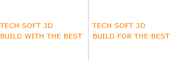
The original (left) and edited text (right)
Note that the row and column counts used as the parameters are offsets, hence the first column would be column zero. HPS::TextKey::EditTextByReplacement can also be used but it is a 1-to-1 operation and is therefore only useful if you’re replacing a substring with string of equal length.
Computing Text Extent
Often, it is necessary to know in advance what size text is going to be drawn on the screen so that it can be positioned accurately within the scene, or so geometry can be properly drawn around the text. Visualize can compute text extents for you based on the font and window characteristics. Because the calculation relies on many top-level parameters (such as screen resolution), you need to use a HPS::KeyPath object, which builds a segment hierarchy from the text object to the top-level window. Information on using a key path can be found in this section.
The size of the text extents are returned as a fraction of the text’s parent window (or subwindow).
    float out_xfrac, out_yfrac;
    myKeyPath.ComputeTextExtent("My text string....", out_xfrac, out_yfrac);
float out_xfrac, out_yfrac;
myKeyPath.ComputeTextExtent("My text string...", out out_xfrac, out out_yfrac);
Setting a Text Region
Computing the text extents returns the screen size of text, but it is sometimes desirable to do the opposite: to specify a screen-space extent that you want the text to be drawn within. This is useful when text needs to fit into a predefined area. In Visualize, this box is called a text region. Text regions are linear in shape, but text path, alignment, and rotation values will continue to be honored. For example, if you wanted to draw text between the points [-1, 0, 0] and [1, 0, 0], you could do something like this:
    HPS::TextKey myTextKey = mySegmentKey.InsertText(Point(0, 0, 0), "This is my text!");

    PointArray pointArray;
    pointArray.push_back(Point(-1, 0, 0));
    pointArray.push_back(Point(1, 0, 0));
    Text::RegionFitting fitting = Text::RegionFitting::Auto;
    bool adjust_direction = true;
    bool relative_coordinates = true;
    bool window_space = false;

    myTextKey.SetRegion(
        pointArray, HPS::Text::RegionAlignment::Center, fitting, adjust_direction, relative_coordinates, window_space);
TextKey myTextKey = mySegmentKey.InsertText(new HPS.Point(0, 0, 0), "This is my text!");

HPS.Point[] pointArray = new HPS.Point[] { new HPS.Point(-1, 0, 0), new HPS.Point(1, 0, 0) };
bool adjust_direction = true;
bool relative_coordinates = true;
bool window_space = false;

myTextKey.SetRegion(pointArray,
                    HPS.Text.RegionAlignment.Center,
                    HPS.Text.RegionFitting.Auto,
                    adjust_direction,
                    relative_coordinates,
                    window_space);

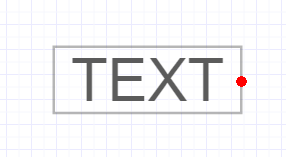
In this example, the text is formatted to fit between the two points, marked by red dots.
To unset a text region, call the above method with zero points in the region argument.
Enabling Text Transformations
When text is part of a scene, it is often necessary for the text to remain unaffected by the camera orientation so that text is always billboarded in the view. This billboarding effect is the Visualize default. To force text to obey modelling transformations, simply enable text transforms in the following way:
mySegmentKey.GetTextAttributeControl().SetTransform(HPS::Text::Transform::Transformable);
mySegmentKey.GetTextAttributeControl().SetTransform(HPS.Text.Transform.Transformable);
Visualize also provides two other types of text transforms that relate to individual characters within a text string. CharacterPositionOnly will enable transforms on the text’s path but the orientation of individual characters remains unaffected.
mySegmentKey.GetTextAttributeControl().SetTransform(HPS::Text::Transform::CharacterPositionOnly);
mySegmentKey.GetTextAttributeControl().SetTransform(HPS.Text.Transform.CharacterPositionOnly);
Alignment and Justification
Setting text alignment changes the position of the text relative to its insertion point. For example, when a text alignment of HPS::Text::Alignment::BottomLeft is used, the text is aligned such that the insertion point is at its bottom left. A list of all possible alignment values can be found in the API reference manual under HPS::Text::Alignment.
    mySegmentKey.GetTextAttributeControl().SetAlignment(HPS::Text::Alignment::BottomLeft);
    mySegmentKey.InsertText(Point(0, 0, 0), "Tech Soft 3D");
mySegmentKey.GetTextAttributeControl().SetAlignment(HPS.Text.Alignment.BottomLeft);
mySegmentKey.InsertText(new HPS.Point(0, 0, 0), "Tech Soft 3D");

The text aligned with the insertion point at the bottom left. The red mark is the insertion point.
Justification controls how the lines of multiline text are displayed relative to other lines in the same text object. Remember that new lines are created through the use of ‘n’.
    mySegmentKey.GetTextAttributeControl().SetAlignment(
        HPS::Text::Alignment::Center, HPS::Text::ReferenceFrame::WorldAligned, HPS::Text::Justification::Right);

    mySegmentKey.InsertText(Point(0, 0, 0), "Choose\nTech Soft 3D\nfor high\nperformance\ngraphics");
mySegmentKey.GetTextAttributeControl().SetAlignment(HPS.Text.Alignment.Center,
                                                    HPS.Text.ReferenceFrame.WorldAligned,
                                                    HPS.Text.Justification.Right);

mySegmentKey.InsertText(new HPS.Point(0, 0, 0), "Choose\nTech Soft 3D\nfor high\nperformance\ngraphics");
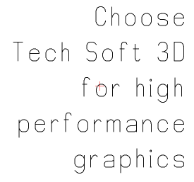
The text is right-justified with a center alignment.
Note the second parameter to HPS::TextKey::SetAlignment, HPS::Text::ReferenceFrame::WorldAligned. This parameter sets the orientation of the text region, and is particularly important when using rotated text. When using a WorldAligned orientation, the text region is aligned to the world coordinate system. When using a PathAligned orientation, the text region is oriented to the text’s path (shown below, rotated 30 degrees). Note that when transforming text, the transform flag must be set to HPS::Text::Transform::Transformable.
    HPS::TextKey textKey = mySegmentKey.InsertText(Point(0, 0, 0), "Choose\nTech Soft 3D\nfor high\nperformance\ngraphics");

    mySegmentKey.GetTextAttributeControl().SetFont("stroked");
    mySegmentKey.GetTextAttributeControl().SetSize(40, HPS::Text::SizeUnits::Points);
    mySegmentKey.GetModellingMatrixControl().Rotate(0, 0, 30); // text rotated 30 degrees
    mySegmentKey.GetTextAttributeControl().SetTransform(HPS::Text::Transform::Transformable);
HPS.TextKey textKey = mySegmentKey.InsertText(new HPS.Point(0, 0, 0), "Choose\nTech Soft 3D\nfor high\nperformance\ngraphics");

mySegmentKey.GetTextAttributeControl().SetFont("stroked");
mySegmentKey.GetTextAttributeControl().SetSize(40, HPS.Text.SizeUnits.Points);
mySegmentKey.GetModellingMatrixControl().Rotate(0, 0, 30); // text rotated 30 degrees
mySegmentKey.GetTextAttributeControl().SetTransform(HPS.Text.Transform.Transformable);
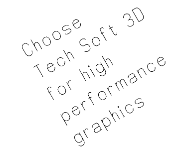
A rotated text block
Another possibility allows you to rotate the text path around the insertion point without rotating the characters. You can do this by assigning a path for the text to follow. However, in most cases, the desired effect is to have the characters rotate along with the entire text block. While you can achieve this same effect using a modelling matrix rotation, this method is useful when you don’t want the text to otherwise be affected by segment-level transformations.
    // allows text to be "rotated" even when not transformable
    mySegmentKey.GetTextAttributeControl().SetPath(Vector(1, 0.5f, 0));

    // allows characters to be rotated with inside block
    mySegmentKey.GetTextAttributeControl().SetRotation(HPS::Text::Rotation::FollowPath);
// allows text to be "rotated" even when not transformable
mySegmentKey.GetTextAttributeControl().SetPath(new HPS.Vector(1, 0.5f, 0));

// allows characters to be rotated inside text block
mySegmentKey.GetTextAttributeControl().SetRotation(HPS.Text.Rotation.FollowPath);
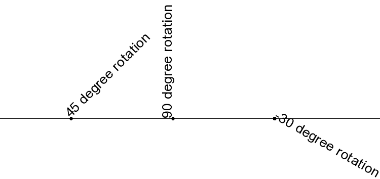
Rotating text around the insertion point. HOOPS Visualize rotates text in a counter-clockwise direction starting from the positive X axis.
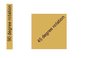
Note that the previous result rotates the text alone, and is possible if you aren’t using a text background. If you use a text background, the background is not rotated with the text and you could end up with an undesirable result:
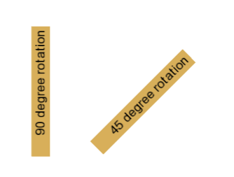
In order to resolve this issue, you must set the text transform type to Transformable, then rotate the segment:
	mySegmentKey.InsertText(Point(0, 0, 0), "45 degree rotation");
	mySegmentKey.GetTextAttributeControl().SetTransform(HPS::Text::Transform::Transformable);
	mySegmentKey.GetModellingMatrixControl().Rotate(0, 0, 45);
mySegmentKey.InsertText(new Point(1, 0, 0), "45 degree rotation");
mySegmentKey.GetTextAttributeControl().SetTransform(HPS.Text.Transform.Transformable);
mySegmentKey.GetModellingMatrixControl().Rotate(0, 0, 45);
This will result in the background being rotated with the text:
Rotating characters
It is also possible to rotate each text character instead of the whole block. To do this, you would replace the call to rotate the modelling matrix with:
mySegmentKey.GetTextAttributeControl().SetRotation(40);
mySegmentKey.GetTextAttributeControl().SetRotation(40);

A text block with characters rotated 40 degrees
Text Greeking
Text greeking is a rendering optimization that is useful when your scene contains a large amount of text. Text can be slow to render in some circumstances, and when text appears very small on the screen, the trade-off between rendering speed and usefulness is important to consider. Text greeking solves this problem by ignoring text that would be drawn below a certain arbitrary size. Alternatively, Visualize can draw a box or lines in place of the text so there is some indication that text is present, but simply too small to be drawn.
Since text is only subject to zoom when it is transformable, text transforms must be enabled in order for greeking to be useful. The code sample below will enable greeking for text sized below 6 points.
    mySegmentKey.GetTextAttributeControl().SetTransform(HPS::Text::Transform::Transformable);
    mySegmentKey.GetTextAttributeControl().SetGreeking(true, 6, HPS::Text::GreekingUnits::Points, HPS::Text::GreekingMode::Box);
mySegmentKey.GetTextAttributeControl().SetTransform(HPS.Text.Transform.Transformable);
mySegmentKey.GetTextAttributeControl().SetGreeking(true, 6,
    HPS.Text.GreekingUnits.Points, HPS.Text.GreekingMode.Box);
Text Backgrounds
HOOPS Visualize can draw backgrounds around text automatically. You can control the shape of the background and the width of the margins. Text backgrounds will inherit attributes from the containing segment, which enables you to control the color and edge pattern. Text backgrounds will also wrap properly around transformed text.
The color of the background is that of faces, and the color of the lines around the background is that of edges. So, for example, changing the edge color to blue for the segment which contains the text will change the color of the edges of the text background to blue as well.
There are four pre-defined background shapes: “oval”, “ellipse”, “rounded box”, or “box”. It is also possible to define a custom shape.
    HPS::TextKit textKit;
    textKit.SetPosition(Point(0, 0.25f, 0));
    textKit.SetText("TECH SOFT 3D");
    textKit.SetSize(30, HPS::Text::SizeUnits::Pixels);
    textKit.SetAlignment(HPS::Text::Alignment::Center); // relative to insertion point
    textKit.SetBackground(true, "oval"); // also valid are "ellipse", "box", and "rounded box"
    mySegmentKey.GetMaterialMappingControl().SetFaceColor(RGBAColor(0.5f, 0, 0.5f));
    mySegmentKey.GetMaterialMappingControl().SetEdgeColor(RGBAColor(0, 1, 0));
    mySegmentKey.GetVisibilityControl().SetFaces(true).SetEdges(true);
    mySegmentKey.InsertText(textKit);
HPS.TextKit textKit = new TextKit();
textKit.SetPosition(new Point(0, 0.25f, 0));
textKit.SetText("TECH SOFT 3D");
textKit.SetSize(30, HPS.Text.SizeUnits.Pixels);
textKit.SetAlignment(HPS.Text.Alignment.Center); // relative to insertion point
textKit.SetBackground(true, "oval"); // also valid are "ellipse", "box", and "rounded box"
mySegmentKey.GetMaterialMappingControl().SetFaceColor(new RGBAColor(0.5f, 0, 0.5f));
mySegmentKey.InsertText(textKit);
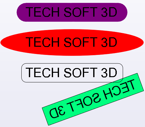
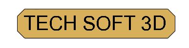
Text backgrounds may be set to “oval”, “ellipse”, “rounded box”, or “box”
Additionally, it is possible to style the text background so that it can be of a specific color regardless of the segment’s face and edge color. To do this, use the function SetBackgroundStyle. The name passed to this function a named style, which is defined in a portfolio accessible from the containing segment.
    // first, define the style
    SegmentKey styleSegment = Database::CreateRootSegment();
    styleSegment.GetMaterialMappingControl().SetFaceColor(RGBColor(1, 1, 0)).SetEdgeColor(RGBColor(0, 0, 1));
    styleSegment.GetEdgeAttributeControl().SetWeight(5).SetPattern("dashed_pattern");
    myPortfolio.DefineNamedStyle("myShapeStyle", styleSegment);

    // apply the defined style to the text segment
    SegmentKey containingSegment = mySegmentKey.Subsegment();
    containingSegment.GetTextAttributeControl().SetBackgroundStyle("myShapeStyle");
// first, define the style
SegmentKey styleSegment = Database.CreateRootSegment();
styleSegment.GetMaterialMappingControl().SetFaceColor(new RGBAColor(1, 1, 0)).SetEdgeColor(new RGBAColor(0, 0, 1));
styleSegment.GetEdgeAttributeControl().SetWeight(5).SetPattern("dashed_pattern");
myPortfolio.DefineNamedStyle("myShapeStyle", styleSegment);

// apply the defined style to the text segment
SegmentKey containingSegment = mySegmentKey.Subsegment();
containingSegment.GetTextAttributeControl().SetBackgroundStyle("myShapeStyle");
Custom Shapes
Custom shape backgrounds can also be defined for use with text using a HPS::ShapeDefinition. Shape definitions work like all other definitions in HOOPS Visualize:
The developer fills out the fields of an
HPS::ShapeKitobject to determine how the shape should lookThe developer uses the
HPS::ShapeKitto define a shape in a portfolio and to give that shape a nameThe developer uses the name of the shape definition to tell HOOPS Visualize which background shape to use
Users define their own shapes by adding one or more shape elements to a HPS::ShapeKit. There are seven different kinds of shape elements:
polygon
ellipse
circle
elliptical
circular
line
anchor
To define any of these elements, you use a special 2D point class called HPS::ShapePoint. Each HPS::ShapePoint is made up of two HPS::ShapeCoordinate objects. Although named HPS::ShapeCoordinate, these objects themselves do not represent an X-Y coordinate until used as part of a HPS::ShapePoint. This is because HPS::ShapeCoordinate alone is merely a directionless distance.
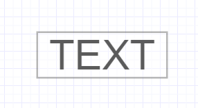
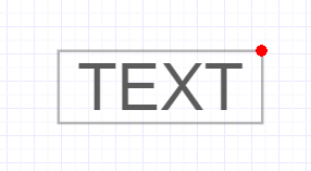
HPS::ShapeCoordinate objects accept up to 5 parameters, which are normalized based on the bounds of the text and its margins. Imagine this is the text you are inserting (the grey box represents the text bounding):
The HPS::ShapeCoordinate parameters are multiples of the size of the text bounding box. These parameters are summed to form a distance. As an example, consider the following HPS::ShapeCoordinate objects:
        ShapeCoordinate sc1(1.15, 0);
        ShapeCoordinate sc2(0.85, 1.5);
        ShapePoint sp(sc1, sc2);
ShapeCoordinate sc1 = new ShapeCoordinate(1.15f, 0);
ShapeCoordinate sc2 = new ShapeCoordinate(0.85f, 1.5f);
ShapePoint sp = new ShapePoint(sc1, sc2);
Let’s imagine the text bounding box is 400 pixels by 150 pixels. The code above means that sc1 will be 400 * 1.15 + 150 * 0 = 460 pixels. sc2 will be 400 * 0.85 + 150 * 1.5 = 565 pixels. sp will then have X-Y coordinates of (460, 565) relative to the center of the text. The code below uses 100% of the X and Y bounding to locate the corner of the text. Therefore,
        ShapeCoordinate sc1(1, 0);
        ShapeCoordinate sc2(0, 1);
        ShapePoint(sc1, sc2);
ShapeCoordinate sc1 = new ShapeCoordinate(1, 0);
ShapeCoordinate sc2 = new ShapeCoordinate(0, 1);
ShapePoint sp = new ShapePoint(sc1, sc2);
…will define this point:
Similarly, these coordinates…
        ShapeCoordinate sc1(1, 0);
        ShapeCoordinate sc2(0, 0);
        ShapePoint(sc1, sc2);
ShapeCoordinate sc1 = new ShapeCoordinate(1, 0);
ShapeCoordinate sc2 = new ShapeCoordinate(0, 0);
ShapePoint sp = new ShapePoint(sc1, sc2);
…define the following location:
In addition to the normalized X and Y values for the text bounding box, you may optionally specify a radius. The radius works the same way - it is a multiple of the distance from the center of the text to the circle that circumscribes the text bounding box. This is useful if you wish to create a circular background.
Text margins can also be specified. Margins are optional values which the user can set which can be used so that the text background does not hug the text too closely. For example, the default text background looks like this if no margins are used:
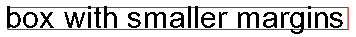
Up to four margin values can be preset by calling the function SetBackgroundMargins. Although called margins, they are simply four values that are added together to the computed HPS::ShapeCoordinate - they do not necessarily represent the four sides of the text. Margin size is relative to the height of the text characters. Margins are set by default to 50% of character height and can be changed using HPS::TextAttributeControl::SetBackgroundMargins.
Use the HPS::ShapeCoordinate::SetMargins function to define a multiple of how far in each direction the margin will extend, as a percentage of the character size. Different margin values are summed to created the final size. For example:
    // set margin size to 40% of character height
    mySegmentKey.GetTextAttributeControl().SetBackgroundMargins(40);

    sc1.SetMargins(1, 0, 0, 0); // 100% of margin size = 40% of char height
    sc2.SetMargins(0, 3, 2, 0); // 300% of margin size + 200% of margin size * 40% = 200% of char height
    sc3.SetMargins(0, 0, -1, 0); // -100% of margin size = -40% of char height
    sc4.SetMargins(0, 0, 0, -2.5f); // -300% of margin size = -100% of char height
// set margin size to 40% of character height
mySegmentKey.GetTextAttributeControl().SetBackgroundMargins(40);

sc1.SetMargins(1, 0, 0, 0); // 100% of margin size = 40% of char height
sc2.SetMargins(0, 3, 2, 0); // 300% of margin size + 200% of margin size * 40% = 200% of char height
sc3.SetMargins(0, 0, -1, 0); // -100% of margin size = -40% of char height
sc4.SetMargins(0, 0, 0, -2.5f); // -300% of margin size = -100% of char height
When the computed value is negative, it will result in the final HPS::ShapePoint moved in the -X or -Y direction. In the previous snippet, we set the background margins to 40 percent of the character height. Let’s imagine the character height for the text we are inserting is 20 pixels. This means:
sc1 margin size is 0.4 * 20 = 8 pixels
sc2 margin size is 2.0 * 20 = 40 pixels
sc3 margin size is -0.4 * 20 = -8 pixels
sc4 margin size is -2.5 * 20 = -20 pixels
The computed margin value is added with the normalized X and Y values for the text bounding box as well as any radius value that has been specified. You typically will not use all possible combinations of parameters when creating these shapes, only those which are necessary to create the shape you need. At this point, we have all the information we need to start creating custom shapes. For example, this is how you create a modified rectangle shape with clipped edges:
    // first, build the shape points
    ShapeCoordinate x(1, 0);
    ShapeCoordinate y(0, 1);
    ShapeCoordinate neg_x(-1, 0);
    ShapeCoordinate neg_y(0, -1);

    ShapeKit clippedShapeKit;
    ShapePoint clipped_points[] = {ShapePoint(x.SetMargins(1), y),
                                   ShapePoint(x.SetMargins(0), y.SetMargins(1)),
                                   ShapePoint(neg_x, y),
                                   ShapePoint(neg_x.SetMargins(-1), y.SetMargins(0)),
                                   ShapePoint(neg_x, neg_y),
                                   ShapePoint(neg_x.SetMargins(0), neg_y.SetMargins(-1)),
                                   ShapePoint(x, neg_y),
                                   ShapePoint(x.SetMargins(1), neg_y.SetMargins(0))};

    // use the points to create a shape element
    PolygonShapeElement clipped_element(8, clipped_points);
    clippedShapeKit.SetElement(clipped_element);

    // define the shape in a portfolio accessible to the segment
    myPortfolio.DefineShape("clipped background shape", clippedShapeKit);

    // now, set the background shape on the text
    HPS::TextKit textKit;
    textKit.SetPosition(Point(0, 0.25f, 0));
    textKit.SetText("TECH SOFT 3D");
    textKit.SetSize(30, HPS::Text::SizeUnits::Pixels);
    textKit.SetAlignment(HPS::Text::Alignment::Center); // relative to insertion point
    textKit.SetBackground(true, "clipped background shape");
    mySegmentKey.InsertText(textKit);
// first, build the shape points
ShapeCoordinate x = new ShapeCoordinate(1, 0);
ShapeCoordinate y = new ShapeCoordinate(0, 1);
ShapeCoordinate neg_x = new ShapeCoordinate(-1, 0);
ShapeCoordinate neg_y = new ShapeCoordinate(0, -1);

ShapeKit clippedShapeKit = new ShapeKit();
ShapePoint [] clipped_points = new ShapePoint[]
{
    new ShapePoint(x.SetMargins(1), y),
    new ShapePoint(x.SetMargins(0), y.SetMargins(1)),
    new ShapePoint(neg_x, y),
    new ShapePoint(neg_x.SetMargins(-1), y.SetMargins(0)),
    new ShapePoint(neg_x, neg_y),
    new ShapePoint(neg_x.SetMargins(0), neg_y.SetMargins(-1)),
    new ShapePoint(x, neg_y),
    new ShapePoint(x.SetMargins(1), neg_y.SetMargins(0))
};

// use the points to create a shape element
PolygonShapeElement clipped_element = new PolygonShapeElement(clipped_points);
clippedShapeKit.SetElement(clipped_element);

// define the shape in a portfolio accessible to the segment
myPortfolio.DefineShape("clipped background shape", clippedShapeKit);

// now, set the background shape on the text
TextKit textKit = new TextKit();
textKit.SetPosition(new Point(0, 0.25f, 0));
textKit.SetText("TECH SOFT 3D");
textKit.SetSize(30, HPS.Text.SizeUnits.Pixels);
textKit.SetAlignment(HPS.Text.Alignment.Center); // relative to insertion point
textKit.SetBackground(true, "clipped background shape");
mySegmentKey.InsertText(textKit);
Using GD&T Symbols
Geometry, Dimension & Tolerance [GD&T] symbols are used by the engineering industry to delineate geometric features that would be cumbersome to otherwise describe. Visualize supports the use of such symbols, provided you are using a font which defines them. The “ts3d” font, distributed with Visualize, is such a font. As the symbols are outside the ASCII character set, you must make sure they are UTF-8 encoded when inserting them. The HPS::UTF8 class is provided to facilitate the encoding. In C#, simply use the String object. The following code sample demonstrates how to do this:
    wchar_t text[40];
    wcscpy(text, L"TECH SOFT 3D ");

    wchar_t gdt[] = {0x2197, 0x2300, 0x21A7, 0};
    wcscat(text, gdt);

    HPS::UTF8 gdt_str(text);
    mySegmentKey.InsertText(Point(0, 0, 0), gdt_str);
    mySegmentKey.GetTextAttributeControl().SetFont("ts3d");
String text = "TECH SOFT 3D\u2197\u2300\u21A7";
HPS.TextKey tk = mySegmentKey.InsertText(new HPS.Point(0, 0, 0), text);
mySegmentKey.GetTextAttributeControl().SetFont("ts3d");
For a list of all GD&T symbols, see the appendix.
Working With Non-Latin Characters
If you’re using non-Latin characters, such as Chinese or Hebrew, please note that the “stroked” and “ts3d” fonts don’t provide these characters. For Windows users, fonts that support non-Latin characters are usually available in the system’s font directory; for Ubuntu users, available fonts are located in /usr/share/fonts.
Here is an example of how to change the font to one that supports Chinese characters:
    // Get the root segment
    SegmentKey modelSegment = _canvas.GetFrontView().GetAttachedModel().GetSegmentKey();

    // Set the visibility for text segment
    modelSegment.GetVisibilityControl().SetText(true);

    HPS::UTF8 font;

    // Use "Microsoft YaHei" font in the Windows system font directory
    modelSegment.GetTextAttributeControl().SetFont("Microsoft YaHei");

    // Check whether we've set the font successfully (view result in Debugger).
    modelSegment.GetTextAttributeControl().ShowFont(font);
    modelSegment.InsertText(Point(0, 0, 0), (HPS::UTF8)L"Chinese Characters 中国智造");
    modelSegment.GetTextAttributeControl().SetAlignment(HPS::Text::Alignment::Center);
// Get the root segment
SegmentKey modelSegment = _canvas.GetFrontView().GetAttachedModel().GetSegmentKey();

// Set the visibility for text segment
modelSegment.GetVisibilityControl().SetText(true);

String font;
// Use "Microsoft YaHei" font in system font directory
modelSegment.GetTextAttributeControl().SetFont("Microsoft YaHei");

// Check whether we've set the font successfully (view result in Debugger).
modelSegment.GetTextAttributeControl().ShowFont(out font);
modelSegment.InsertText(new Point(0, 0, 0), (String)"Chinese Characters 中国智造");
modelSegment.GetTextAttributeControl().SetAlignment(HPS.Text.Alignment.Center);
One current limitation is that GD&T symbols aren’t supported by many of the commonly used system fonts, so if you’re using GD&T symbols, it’s important to find a font that supports your language of choice as well as GD&T symbols, or to create a workflow that alternates between the fonts required for your language and GD&T symbols.
