Line Patterns
Visualize supports an advanced feature set for line patterns. You can use one of the pre-defined line patterns by defining it in the active portfolio and instructing the segment to use that pattern. For example, to set the “dashdot” line pattern, you could use the following code:
    HPS::LinePatternKit myLinePatternKitpk = HPS::LinePatternKit::GetDefault(HPS::LinePattern::Default::Dashed);

    myPortfolio.DefineLinePattern("my_new_pattern", myLinePatternKitpk);

    mySegmentKey.GetLineAttributeControl().SetPattern("my_new_pattern");
HPS.LinePatternKit myLinePatternKit = HPS.LinePatternKit.GetDefault(HPS.LinePattern.Default.Dashed);

myPortfolio.DefineLinePattern("my_new_pattern", myLinePatternKit);

mySegmentKey.GetLineAttributeControl().SetPattern("my_new_pattern");
For a list of all pre-defined line patterns, as well as their names, see the appendix section on lines.
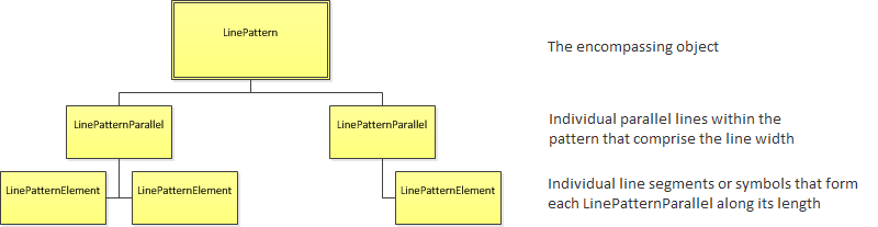
Custom line patterns are also available. To define a custom pattern, it is necessary to understand the hierarchy involved. Line patterns are comprised of one or more parallels. Each parallel describes a set of elements which will be drawn along the path of a line. The elements can be solid pixels, blank pixels, or glyphs. The object hierarchy is shown below:
The procedure for building these objects is described in the steps below:
Step 1: Initialize the LinePatternElements
For this example, a double line composed of two parallels will be built: a solid blue and a dashed orange line. Working from the bottom of the hierarchy to the top, the first step is to initialize each HPS::LinePatternElement. The code below initializes the individual line patterns for use within the line as a whole. Note that a dashed line is actually made of two elements: a repeating pattern of solids and blanks.
    HPS::SolidLinePatternElement slpe_orange;
    slpe_orange.SetSize(50, HPS::LinePattern::SizeUnits::Pixels); // each dash set to 50 pixel in length
    slpe_orange.SetColor(HPS::RGBColor(1, 0.5, 0)); // color set to orange

    HPS::BlankLinePatternElement blpe;
    blpe.SetSize(20, HPS::LinePattern::SizeUnits::Pixels); // each space between dashes is set to 20 pixels

    HPS::SolidLinePatternElement slpe_blue; // this will be the blue solid line
    slpe_blue.SetColor(HPS::RGBColor(0, 0, 1));
HPS.SolidLinePatternElement slpe_orange = new HPS.SolidLinePatternElement();
slpe_orange.SetSize(50, HPS.LinePattern.SizeUnits.Pixels); // each dash set to 50 pixel in length
slpe_orange.SetColor(new HPS.RGBAColor(1, 0.5f, 0));       // color set to orange

HPS.BlankLinePatternElement blpe = new HPS.BlankLinePatternElement();
blpe.SetSize(20, HPS.LinePattern.SizeUnits.Pixels);        // each space between dashes is set to 20 pixels

// this will be the blue solid line
HPS.SolidLinePatternElement slpe_blue = new HPS.SolidLinePatternElement();
slpe_blue.SetColor(new HPS.RGBAColor(0, 0, 1));
Step 2: Combine the LinePatternElements into an Array
Now that the HPS::LinePatternElement objects are initialized, the next step is to assemble them into a collection. Like the HPS::GlyphElement objects discussed in this section, they all need to be combined into an array. Since a line made of two parallels is desired, two arrays are needed. The order of the elements in the array will determine their order in the rendered line.
    HPS::LinePatternElementArray lpea_dashed;

    lpea_dashed.push_back(slpe_orange); // adding the SolidLinePatternElement from step 1
    lpea_dashed.push_back(blpe); // adding the BlankLinePatternElement from step 1

    HPS::LinePatternElementArray lpea_solid; // this will be the blue solid line
    lpea_solid.push_back(slpe_blue);
HPS.LinePatternElement[] lpea_dashed = new HPS.LinePatternElement[2];

lpea_dashed[0] = slpe_orange;  // adding the SolidLinePatternElement from step 1
lpea_dashed[1] = blpe;         // adding the BlankLinePatternElement from step 1

HPS.LinePatternElement[] lpea_solid = new HPS.LinePatternElement[1]; // this will be the blue solid line
lpea_solid[0] = slpe_blue;
Step 3: Set Up the LinePatternParallels
Each HPS::LinePatternElementArray now needs to be made into a parallel. The parallel objects allow the offset (distance between the parallels and the line path) and weight to be set. The parallels live inside a HPS::LinePatternParallelKitArray.
    HPS::LinePatternParallelKitArray lppka(2);

    lppka[0]
        .SetBody(lpea_dashed)
        .SetOffset(4, HPS::LinePattern::SizeUnits::Pixels)
        .SetWeight(2, HPS::LinePattern::SizeUnits::Pixels);
    lppka[1].SetBody(lpea_solid);
HPS.LinePatternParallelKit[] lppka = { new HPS.LinePatternParallelKit(), new HPS.LinePatternParallelKit() };

lppka[0].SetBody(lpea_dashed).SetOffset(4, HPS.LinePattern.SizeUnits.Pixels).SetWeight(2, HPS.LinePattern.SizeUnits.Pixels);
lppka[1].SetBody(lpea_solid);
Step 4: Add the Parallels to the Line Pattern Itself
A HPS::LinePatternKit is used to conglomerate all of the line pattern data. After the kit is built, the construction phase of the line pattern is complete.
    HPS::LinePatternKit lpk;

    lpk.SetParallels(lppka);
HPS.LinePatternKit lpk = new HPS.LinePatternKit();

lpk.SetParallels(lppka);
Step 5: Add Line Pattern to a Portfolio
Before using the line pattern, it must be defined in a portfolio. Don’t forget to set the portfolio on the segment you intend to use it on. Portfolios are introduced here.
    myPortfolio.DefineLinePattern("myLinePattern", lpk);

    mySegmentKey.GetPortfolioControl().Push(myPortfolio);
myPortfolio.DefineLinePattern("myLinePattern", lpk);

mySegmentKey.GetPortfolioControl().Push(myPortfolio);
Step 6: Line Pattern is Ready to Be Set On a Line
At this point, the line pattern is defined and ready to use. As line patterns are controlled at the segment level, the pattern must be set there.
    mySegmentKey.GetLineAttributeControl().SetPattern("myLinePattern");
    mySegmentKey.InsertLine(HPS::Point(-10, 0, 0), HPS::Point(10, 0, 0));
    mySegmentKey.GetVisibilityControl().SetLines(true); // ensure lines visible
mySegmentKey.GetLineAttributeControl().SetPattern("myLinePattern");

mySegmentKey.InsertLine(new HPS.Point(-10, 0, 0), new HPS.Point(10, 0, 0));
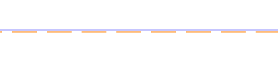
The completed custom line pattern
Using Glyphs in a Line Pattern
Glyphs can also be used as elements in a line pattern. To do so, the glyph must be already defined (see this section for a discussion on defining glyphs). The steps for using glyphs follow the same basic principles as other types of line pattern elements:
Using a
GlyphLinePatternElement, set the source glyph.Add the
GlyphLinePatternElementto theLinePatternParallelas you would any other line pattern element.Define the line pattern in the portfolio, and make it the active line pattern.
    HPS::GlyphLinePatternElement glpe;
    glpe.SetSource("myGlyph"); // glyph must already be defined in the current portfolio
    glpe.SetInsetBehavior(HPS::LinePattern::InsetBehavior::Inline);

    // ...

    HPS::LinePatternElementArray lpea;
    lpea.push_back(anotherElement);
    lpea.push_back(glpe); // add to the LinePatternElementArray as you would any other line pattern element
    lpea.push_back(anotherElement);

    // ...
HPS.GlyphLinePatternElement glpe = new HPS.GlyphLinePatternElement();
glpe.SetSource("myGlyph");  // glyph must already be defined in the current portfolio
glpe.SetInsetBehavior(HPS.LinePattern.InsetBehavior.Inline);

// ...

HPS.LinePatternElement[] lpea = new HPS.LinePatternElement[3];
lpea[0] = anotherElement;
lpea[1] = glpe;  // add to the LinePatternElementArray as you would any other line pattern element
lpea[2] = anotherElement;

// ...
The remaining steps are nearly identical to building a normal line pattern. Note the call to SetInsetBehavior. The inset behavior will determine whether the glyph is drawn as a distinct element (Inline), overlapping the line elements (Overlap), or a length-trimmed hybrid (Trim). The screenshot below shows an example of all three behaviors.
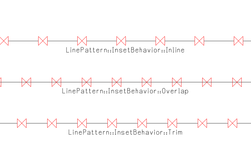
The default inset behavior is ``Overlap``.
