Performance Considerations
The performance of a Visualize application depends on a number of factors. Obviously, scenes with less geometry will generally perform faster than those with more. The available hardware, including GPU and memory, are also frequent bottlenecks. While it can be difficult to anticipate all the configurations that your application will run on, there are steps you can take to ensure that Visualize runs as well as possible.
Segment Organization
Good segment organization is critical, and the most common cause of rendering performance problems is an inefficient scene graph structure. The segment tree is designed to group graphical primitives based on similar graphical attributes. It is a common mistake for programmers to structure their segments to directly match the structure/hierarchy of their application data.
For example, imagine that you are drawing a checkerboard with white and black squares (ignore for a moment that the best way to draw a checkerboard would be with a mesh). The squares cannot all be in a single segment, because they do not all share the same color-attribute value. One way to organize the database is to put each square of the board in its own segment, but that requires 64 different segments. A more efficient organization is to use two segments, and to put all the black squares in one segment, and all the white squares in the other. This structure uses fewer segments, is faster to render, and can make it easier to change attributes (for example, to change all the white squares to red).
Organizing the scene-graph based on graphical attributes helps maintain attribute coherence and minimizes context-switching, which refers to a need for Visualize to reset attributes in the underlying device-driver. Organizing the database is a two-step process. The first step is to put into the same segment all geometry that has the same color, transformation, and other attributes. Some attributes, such as transformations, will naturally tend to follow the organization of the geometry in a scene; if they do, then your segment organization might follow the organization of your geometry, but it will not be dictated by that organization.
The second step is to build an inheritance hierarchy for segments with similar attribute settings. For example, if, in the resulting database, there are two segments with nearly identical attribute values, then you should give them a common parent segment and should set the common attributes in the parent. Notice that organizing an attribute hierarchy is similar to designing a good class hierarchy in C++. Continue until your attributes are well organized - the goal is to structure your database so that you can change any attribute that affects a group of geometry by changing it in only one place. For example, if a group of objects will normally move together, give the group a common parent so that you can change the transformation in one place. If two attributes conflict on how they want the database to be organized, consider putting one of the attributes into a style segment.
In summary, the scene graph should be organized to group geometry with like attributes together, and utilize as few segments as possible.
Display Lists
A display list is a set of pre-compiled drawing commands and data that are stored in GPU memory. Use of display lists for retained geometry that is being traversed during each update is key to maximum GPU throughput. Display lists usage is controlled via the HPS::PerformanceControl.
Visualize supports geometry-level and segment-level display lists. Generally, segment-level display lists are the best choice as all geometry and attributes within a segment are grouped and can potentially be defined in a single list. However, if a segment contains a large number of primitives and you are editing or moving some of them frequently, segment-level display lists may not be a good choice as changes will invalidate the list, and the entire list will need to be rebuilt after each edit. There is some amount of overhead associated with compiling the list.
If you are doing many edits in a short amount of time, a reasonable approach would be to move the shells into another segment, and then perform the edits on the moved shells. The new segment should not have the display-list setting at all, since you are changing the geometry every update and thus display lists would provide no benefit. There will be a small hit due to moving the shells out, thus causing the segment-level display list to get invalidated and rebuilt. But the continual editing operation will be much faster with this plan.
Geometry-level display lists will group geometry by type into more numerous lists. This may be a better choice if your scene makes periodic small edits to geometry. When this type of display list is invalidated, only that single, smaller list will need to be rebuilt.
    // enable segment-level display lists
    mySegmentKey.GetPerformanceControl().SetDisplayLists(HPS::Performance::DisplayLists::Segment);

    // enable geometry-level display lists
    mySegmentKey.GetPerformanceControl().SetDisplayLists(HPS::Performance::DisplayLists::Geometry);
// enable segment-level display lists
mySegmentKey.GetPerformanceControl().SetDisplayLists(HPS.Performance.DisplayLists.Segment);

// enable geometry-level display lists
mySegmentKey.GetPerformanceControl().SetDisplayLists(HPS.Performance.DisplayLists.Geometry);
Display lists utilize GPU memory. To avoid low GPU memory conditions, Visualize automatically monitors the amount of video memory it uses and only creates display lists as long as video memory is available.
Segment-level display lists are enabled by default. If you are utilizing the OpenGL driver, display-lists are only activated if you’ve first defined the polygon handedness for the model as described here. However, a polygon handedness should generally ALWAYS be defined since that allows Visualize to also perform back face culling, covered below.
InPlace Overlay
InPlace overlays do not use display lists, so they will have inferior performance to other overlay types. InPlace overlays should only be used if the other overlay types are not suitable for the circumstances. For more information on overlay types, please see the overlays section of this manual.
Static Model
When the static model attribute is set, Visualize will combine the geometry and attributes from multiple segments into a more optimized, internal segment tree. At render time, Visualize renders from this internal segment tree instead of the external scene graph that you have defined. When used in conjunction with segment-level display lists, it can significantly improve rendering performance, because graphical objects will be grouped into larger segment-level display lists and result in better GPU throughput.
    // enable static model
    mySegmentKey.GetPerformanceControl().SetStaticModel(HPS::Performance::StaticModel::Attribute);

    // allows Visualize to use static model optimizations more appropriate for very large models
    mySegmentKey.GetPerformanceControl().SetStaticModel(HPS::Performance::StaticModel::AttributeSpatial);

    // disable static model
    mySegmentKey.GetPerformanceControl().SetStaticModel(HPS::Performance::StaticModel::None);
// enable static model
mySegmentKey.GetPerformanceControl().SetStaticModel(HPS.Performance.StaticModel.Attribute);

// allows Visualize to use static model optimizations more appropriate for very large models
mySegmentKey.GetPerformanceControl().SetStaticModel(HPS.Performance.StaticModel.AttributeSpatial);

// disable static model
mySegmentKey.GetPerformanceControl().SetStaticModel(HPS.Performance.StaticModel.None);
Static model, as its name implies, should be used when you expect your model not to change between updates. For example, you may have view/query logic that is changing a camera in a ‘view’ segment (where that view segment includes the model tree), or is selecting/querying the model. In this case, there are no changes being made to the actual model subtree.
Static Model Regeneration
After making a change that invalidates the static model, there are several options for updating the window and rendering the scene. For optimal performance, the window should be updated using HPS::Window::UpdateType. To see an example of how to use the static model, please see this brief tutorial.
Using HPS::Window::UpdateType::Default, the static model will not be regenerated on the first update immediately following any scene changes that have invalidated the static model subtree. Instead, the static model will be regenerated on the second update as long as no further changes occurred between the two updates which would have invalidated the static model subtree. In other words, Visualize waits until it is reasonably sure that no more breaking changes will occur; this is a performance optimization to avoid generating a static model unnecessarily. Alternatively, if you’d like to force a static model update, use a HPS::Window::UpdateType::CompileOnly or HPS::Window::UpdateType::Exhaustive update type to force static model regeneration on the first update following any static-model-breaking changes.
Deleting, editing and/or creating segments, geometry, or attributes in the portion of the scene-graph that is affected by the static model setting will generally result in a regeneration of the ‘internal’ segment tree associated with that portion of the scene-graph, and the regeneration process can take up significant computing time for large models. For good performance, it is desirable to avoid such regeneration. Below are the operations that do not invalidate the static model.
- Highlighting: Designed specifically to cooperate well with static model, highlighting is by far the best way to make temporary attribute changes to the scene.
- Certain scene edits for HPS::Performance::StaticModel::Attribute:
- Inserting geometry
- Creating an empty segment
- Deleting geometry
- Deleting segments
- Deleting includes
- Moving geometry into a subsegment of its original segment
- Setting certain segment-level attributes:
- Color (except when there are geometry references with color)
- Visibility
- Face pattern
- Edge pattern or weight
- Line pattern or weight
- Marker symbol or size
- Text font, alignment, path, or spacing
- Clip region
- Setting geometry-level attributes
For the edits listed in #2 above, the Static Model is not fully regenerated. Instead, it is patched. Each patch will make the internal static model segment tree slightly less optimal than the original. Each of these patches by itself will have a negligible impact on performance, but the cumulative impact of many patches may cause performance to decline. To avoid such a performance decline, you should minimize the number of edits that you perform. Or you can force regeneration of the static model (creating a fresh, fully optimized segment tree) with a HPS::Window::UpdateType::CompileOnly or HPS::Window::UpdateType::Exhaustive update.
Example Workflow: There are three pieces of geometry in a segment where the color is set to blue, and you want to make just one piece of geometry green. You can create a new subsegment, move the geometry to that new subsegment, and then set the color to green. This edit workflow will not cause a static model regeneration.
Static model can be enabled for just the parts of your scene graph that you know will remain relatively unchanged. The more of your scene graph that is using static model, the better the performance benefit will be. So it is best to have static model enabled model-wide (or as much as possible), and then turned off for the portions of your scene that will be subject to changes.
Static model does not have to be enabled at all times. If you know your model will be subject to a large number of edits, you could disable static model temporarily, and then re-enable it when the end user exits “edit mode”.
We recommend that you try a number of representative models from your data set along with common usage patterns to determine if using the static model option will benefit your application.
To see information about static tree regenerations that may have occurred during an update, populate an HPS::UpdateInfo object using the HPS::WindowInfoControl::ShowLastUpdateInfo() function. The HPS::UpdateInfo object includes the HPS::UpdateInfo::statics_created_count statistic.
Performance Expectations
You should always attempt to organize your scene graph according to the segment organization recommendations. As noted in that section, one of the main guidelines is to group your geometry into as few segments as possible, based on similar attributes. However, sometimes it may be difficult to organize the scene in this way due to the structure of the model itself, and the static model attribute can greatly improve performance. However, if your scene graph is already fairly optimally organized, using static model may not have any noticeable effect.
There are three main factors that determine how much of a performance gain can be realized: the size of your model, its original segment organization, and the usage patterns of your application. For instance, if your application has a viewing mode that allows the end-user to examine (zooming, rotating, and panning the camera) a model without altering it, static model can frequently increase performance.
Setting the static model mode to AttributeSpatial will not result in as large a potential performance gain as Attribute, since additional spatial-based internal segments will be created. However, if fixed framerate is also being utilized (see below), the additional spatial segments will ensure that the most visually important items will be drawn first during each time-bound update.
If you have many logical conditions in your model tree which exclude large parts of the model, consider taking advantage of this situation by using HPS::PerformanceKit::SetStaticConditions. This call will cause the static tree algorithm to completely exclude those branches during its calculations. If something that depends on conditions is included in multiple places (such as more than one view) with different condition set in them, the tree would thrash (regenerate each time it’s drawn). A case like that should stick with the default static tree and not use static conditions.
Culling Optimizations
In computer graphics, culling is the procedure used to identify geometry that is not important enough to be drawn and subsequently prevent it from being rendered. The effect of culling is to speed up the rendering process. Visualize uses a few different types of culling to achieve these aims, as discussed in the next subsections.
Back Face Culling and Handedness
Back face culling is a rendering optimization used to determine whether the back faces of a polygon should be drawn. The determination is made based on whether the polygon’s vertices are oriented in a clockwise or counter-clockwise direction with respect to the active camera. The terms “clockwise” and “counter-clockwise” are merely for convenience - Visualize understands the terms as “left” and “right”. For example, if the user has specified that front-facing polygons are those that are wound counter-clockwise (a handedness of “right”), then any polygons oriented clockwise would be considered to be facing away from the camera and thus will not be rendered. This operation improves performance because the number of polygons Visualize must draw is reduced.
Polygons do not have an inherent front or back face. You make the determination by setting the handedness for faces. Back face culling will not work without a handedness setting.
The code below demonstrates how to enable back face culling and how to set the front-face handedness.
    // enables back-face culling
    mySegmentKey.GetCullingControl().SetBackFace(true);

    // indicates front-facing polygons are those that are wound clockwise/left-handed WRT camera
    mySegmentKey.GetDrawingAttributeControl().SetPolygonHandedness(HPS::Drawing::Handedness::Left);

    // indicates front-facing polygons are those that are wound counter-clockwise/right-handed WRT camera
    mySegmentKey.GetDrawingAttributeControl().SetPolygonHandedness(HPS::Drawing::Handedness::Right);

    // ignores handedness - back-face culling does not work with this setting
    mySegmentKey.GetDrawingAttributeControl().SetPolygonHandedness(HPS::Drawing::Handedness::None);
// enables back-face culling
mySegmentKey.GetCullingControl().SetBackFace(true);

// indicates front-facing polygons are those that are wound clockwise/left-handed WRT camera
mySegmentKey.GetDrawingAttributeControl().SetPolygonHandedness(HPS.Drawing.Handedness.Left);

// indicates front-facing polygons are those that are wound counter-clockwise/right-handed WRT camera
mySegmentKey.GetDrawingAttributeControl().SetPolygonHandedness(HPS.Drawing.Handedness.Right);

// ignores handedness - back-face culling does not work with this setting
mySegmentKey.GetDrawingAttributeControl().SetPolygonHandedness(HPS.Drawing.Handedness.None);
This diagram shows how inserting vertices in a specific order affects the handedness. The left polygon has a left-handed orientation because the vertices have been inserted counter-clockwise [0, 3, 2, 1] with respect to the camera. The right polygon has a right-handed orientation with the order [0, 1, 2, 3].
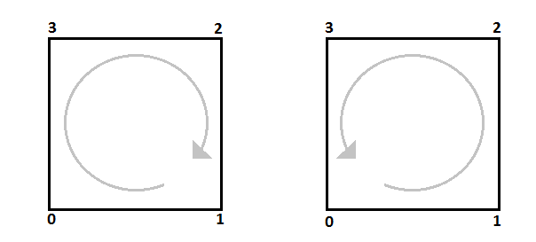
Handedness of a polygon is determined by the order of its vertices
    // for this scene, handedness is set to "Left"
    mySegmentKey.GetDrawingAttributeControl().SetPolygonHandedness(HPS::Drawing::Handedness::Left);
    mySegmentKey.GetCameraControl().SetPosition(Point(0, 0, 5)); // setting the view point

    // specifying a square polygon
    PointArray pointArray(4);
    pointArray[0] = Point(-1.0f, -1.0f, 0);
    pointArray[1] = Point(-1.0f, 1.0f, 0);
    pointArray[2] = Point(1.0f, 1.0f, 0);
    pointArray[3] = Point(1.0f, -1.0f, 0);

    // Inserting the vertices from pointArray in the order 0, 1, 2, 3 will result in the back face
    // toward the camera (right-handed orientation). This face will be culled.
    IntArray faceList(5);
    faceList[0] = 4;
    faceList[1] = 0;
    faceList[2] = 1;
    faceList[3] = 2;
    faceList[4] = 3;

    // merely changing the order of the vertices in the face list results in a front (left-handed) face
    faceList[0] = 4;
    faceList[1] = 0;
    faceList[2] = 3;
    faceList[3] = 2;
    faceList[4] = 1;

    mySegmentKey.InsertShell(pointArray, faceList);
// for this scene, handedness is set to "Left"
mySegmentKey.GetDrawingAttributeControl().SetPolygonHandedness(HPS.Drawing.Handedness.Left);
mySegmentKey.GetCameraControl().SetPosition(new Point(0, 0, 5)); // setting the view point

// specifying a square polygon
HPS.Point[] pointArray = new HPS.Point[4];
pointArray[0] = new HPS.Point(-1.0f, -1.0f, 0);
pointArray[1] = new HPS.Point(-1.0f, 1.0f, 0);
pointArray[2] = new HPS.Point(1.0f, 1.0f, 0);
pointArray[3] = new HPS.Point(1.0f, -1.0f, 0);

// Inserting the vertices from pointArray in the order 0, 1, 2, 3 will result in the back face
// toward the camera (right-handed orientation). This face will be culled.
int[] faceList = new int[5];
faceList[0] = 4;
faceList[1] = 0;
faceList[2] = 1;
faceList[3] = 2;
faceList[4] = 3;

// merely changing the order of the vertices in the face list results in a front (left-handed) face
faceList[0] = 4;
faceList[1] = 0;
faceList[2] = 3;
faceList[3] = 2;
faceList[4] = 1;

mySegmentKey.InsertShell(pointArray, faceList);
In the images below, the two shells are identical, except for the orientation of their faces. The vertices of the first polygon have been inserted in a clockwise, or “left-handed”, orientation. The second polygon’s vertices are counter-clockwise, or “right-handed”. Back-face culling is not enabled in the first image, and both faces are drawn regardless of their orientation. In the second image, the polygon handedness has been set to Left, indicating left-handed polygon faces will not be drawn. Culling has been enabled in the second image to demonstrate this.
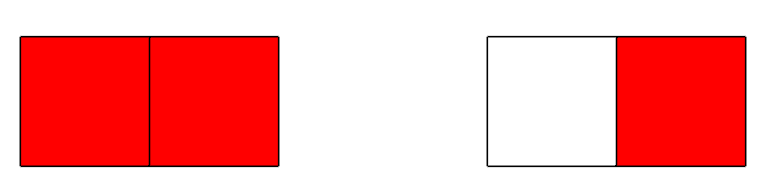
Left image: no culling, and right image: with culling enabled and handedness set to “Left”
Polygon handedness also indicates which way the normals should be directed when assembling shells from a face list. Using the incorrect handedness will result in abnormal lighting effects.
NOTE: Polygon handedness does not take into account the coordinate system handedness and instead assumes that the coordinate system is left-handed. This means that for users of right-handed coordinate systems, the front and back faces of your polygons may appear to be reversed. The problem is solved by setting the polygon handedness to opposite of what it actually is. The reason Visualize assumes a left-handed coordinate system is so that developers can change the coordinate system handedness without having to also change the polygon handedness.
Culling Extents
Some scenes contain many smaller but geometrically detailed parts that are not important to the user’s workflow when their extents fall below a certain size on screen (for example, when zoomed out). In these cases, the user may not care to see every part of the scene, and would rather rendering be completed quickly. Culling extents deals with culling geometry that would be rendered smaller than a certain number of pixels.
Deferral extents is similar to culling extents in that small geometry is marked for culling. However, deferred geometry is still drawn, but only after all other geometry is drawn. This way, non-important geometry still appears, but only when the renderer is otherwise idle. This option is only useful for timed updates, when the scene is drawn piece-by-piece instead of all at once. For more information about timed updates, see the section on fixed framerate mode below.
To enable culling extents or deferral extents:
    // culling all geometry smaller than 10 pixels
    mySegmentKey.GetCullingControl().SetExtent(10);

    // deferring all geometry smaller than 100 pixels
    mySegmentKey.GetCullingControl().SetDeferralExtent(100);
// culling all geometry smaller than 10 pixels
mySegmentKey.GetCullingControl().SetExtent(10);

// deferring all geometry smaller than 100 pixels
mySegmentKey.GetCullingControl().SetDeferralExtent(100);
Frustum Culling
Another culling algorithm is the ‘view frustum’ setting which means that Visualize does a bounding-box check for each segment and shell/mesh primitive. The check determines if the segment/primitive can be viewed by the current camera or lies within the selection region before trying to draw or select it. This is a common culling technique and is on by default; it should only be disabled for debugging purposes. The following code snippet shows how to set this suboption.
    mySegmentKey.GetCullingControl().SetFrustum(true); // enables frustum culling
    mySegmentKey.GetCullingControl().SetFrustum(false); // disables frustum culling
mySegmentKey.GetCullingControl().SetFrustum(true);  // enables frustum culling
mySegmentKey.GetCullingControl().SetFrustum(false); // disables frustum culling
Distance Culling
With distance culling, we can specify a distance in world-coordinates in a HPS::CullingKit or HPS::CullingControl, and any geometry beyond this distance will not be drawn.
The specified distance starts at the camera position point, and every segment whose bounding is within the distance will be drawn, while everything else will be culled.
A typical use case would be a model of a city. By enabling distance culling, our application will render more quickly because buildings that are too far into the distance will be ignored until the camera gets within range of them.
In the following code snippet, we’re simply taking the HPS::CullingControl from our window’s HPS::SegmentKey and passing a distance in world units to HPS::CullingControl::SetDistance() - everything beyond this distance will be culled:
myWindow.GetCullingControl().SetDistance(8.2);
myWindow.GetCullingControl().SetDistance(((float)8.2));
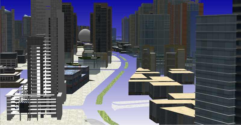
Model of a city with no distance culling
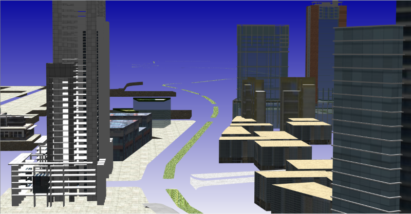
Model of a city with distance culling
In addition to setting our culling distance, we can also create HPS::SelectionOptionsKit that can be used with a selection function (such as HPS::SelectionControl::SelectByPoint()). In this snippet, we’re calling HPS::SelectionOptionsKit::SetDistanceCullingRespected(false), which tells the selection algorithm to ignore distance culling and to include distance-culled objects in our selection results.
    SelectionOptionsKit selection_options = SelectionOptionsKit::GetDefault();
    selection_options.SetDistanceCullingRespected(false);
    SelectionOptionsKit selection_options = SelectionOptionsKit.GetDefault();
    selection_options.SetDistanceCullingRespected(false);
Culling Vector and Vector Tolerance
Vector culling is another setting which allows you to set a vector and tolerance for a given segment. Visualize determines if the segment should be drawn by finding the angular difference between the culling vector and the view vector. If the difference is less than the tolerance angle, then Visualize terminates the tree walk at that segment and it will not be drawn. If you organize your segment tree spatially by faces, then setting these two options could improve the rendering performance significantly.
Volume Culling
HOOPS Visualize can also restrict rendered geometry to a cuboid volume using the HPS::CullingControl. This control will use a volume to only display objects that fall within the bounds of the volume. Culling is a way to potentially increase frame rate because only a subset of the scene’s geometry will be rendered:
    // Get the culling control for the segment where your 3D model has been loaded
    HPS::CullingControl cullControl = mySegKey.GetCullingControl();
    // Create a volume for culling
    HPS::SimpleCuboid volume;
    volume.min = Point(-1000, -1000, -1000);
    volume.max = Point(1000, 1000, 1000);
    cullControl.SetVolume(volume);
        // Get the culling control for the segment where your 3D model has been loaded
        HPS.CullingControl cullControl = mySegKey.GetCullingControl();
        // Create a volume for culling
        HPS.SimpleCuboid volume;
        volume.min = new Point(-1000, -1000, -1000);
        volume.max = new Point(1000, 1000, 1000);
        cullControl.SetVolume(volume);
The HPS::CullingControl is obtained from the segment key that contains the 3D model. We then create a simple cuboid. The dimensions of this cuboid will define what objects will be drawn: Only objects that intersect the boundaries or are contained within them are drawn.
The following are examples of a 3D scene, displayed first with no culling followed by progressively smaller cuboid volumes (and, hence, more objects culled from the scene):
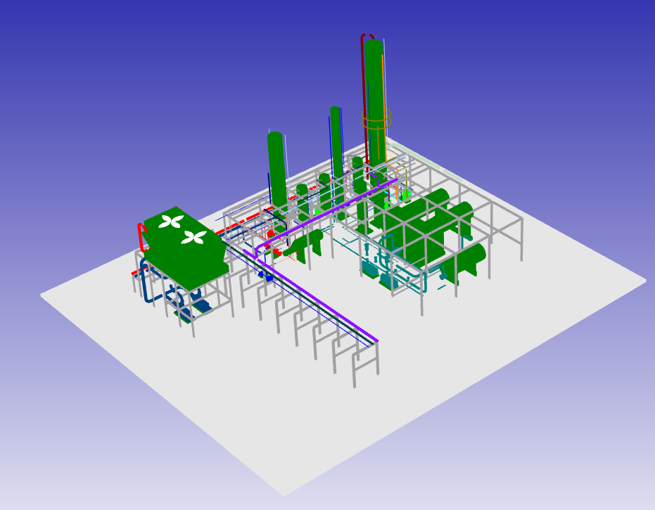
a. No Culling
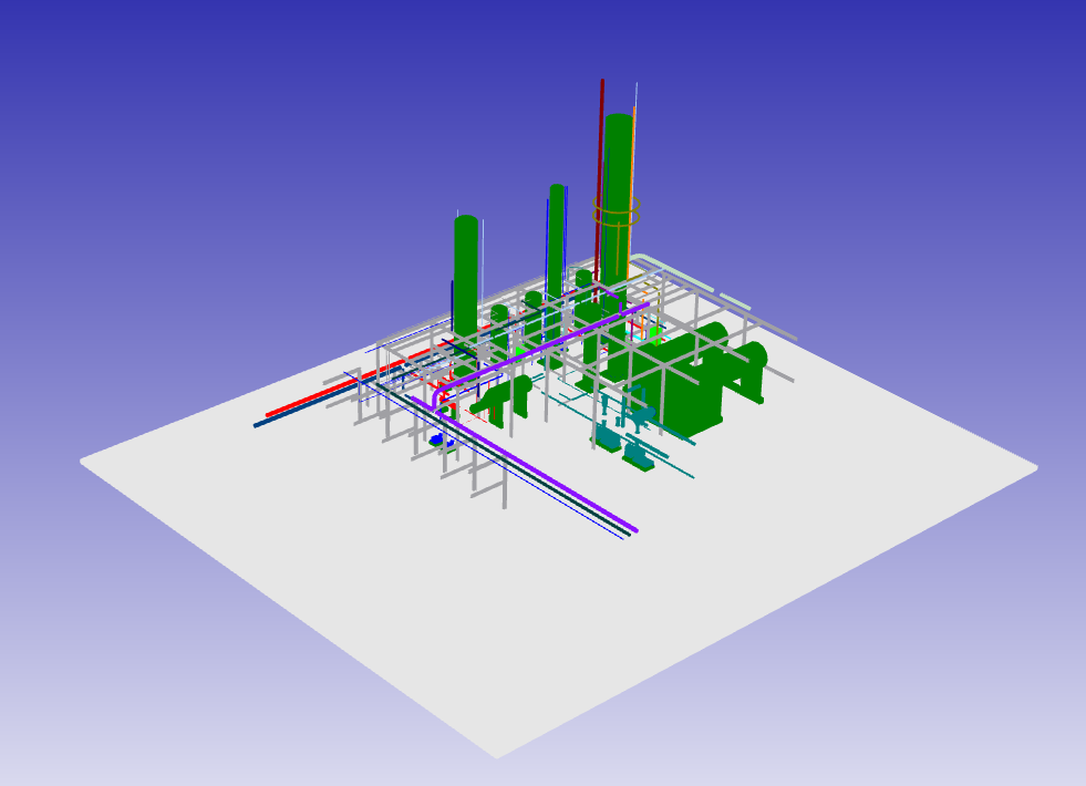
d. 2000x2000x2000 Culling Volume
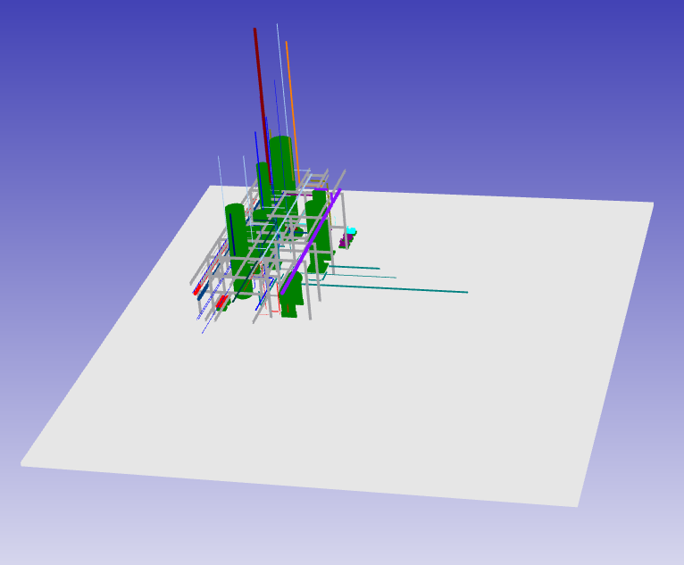
c. 1000x1000x1000 Culling Volume
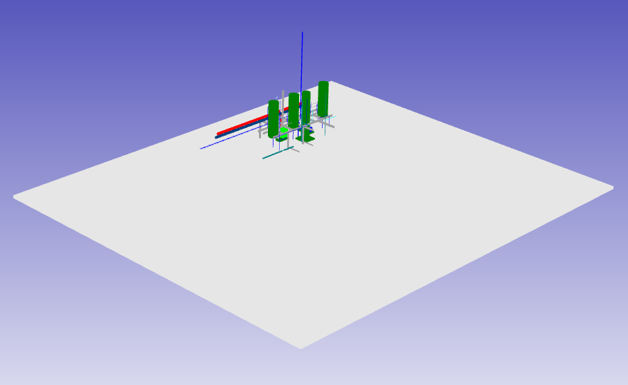
b. 500x500x500 Culling Volume
Fixed Framerate
When working with scenes composed of a large amount of geometry or effects relative to the GPU capabilities, rendering at an interactive speed is not possible. Rather than wait for Visualize to fully redraw the entire scene on each update, it is usually much more preferable to ensure a fixed framerate.
When fixed framerate mode is enabled, Visualize will draw as much of the scene as possible, interrupt the rendering process to ensure that the user-specified framerate value is met, and begin the next update. If another update is not requested (for example, the user stops orbiting the camera), Visualize will continue to render the undrawn parts of the scene until another update request. Even though Visualize will not draw the entire scene, the user will typically prefer to get a smooth framerate regardless of model size, instead of drawing every detail and encountering an unpredictable and slower framerate as model size increases.
Fixed framerate mode is supported via the HPS::Canvas object and is activated by calling HPS::Canvas::SetFrameRate:
    // sets the framerate, hard extents, and deferral size
    canvas.SetFrameRate(20.0f);
    windowKey.GetCullingControl().SetDeferralExtent(100);
    windowKey.GetCullingControl().SetExtent(10);
// sets the framerate, hard extents, and deferral size
canvas.SetFrameRate(20.0f);
windowKey.GetCullingControl().SetDeferralExtent(100);
windowKey.GetCullingControl().SetExtent(10);
In the code above, the parameter to HPS::Canvas::SetFrameRate indicates the number of frames per second that you want to maintain. Culling and deferral extents are also important considerations. In this example, the culling extent value ‘10’ means any entity that would be rendered at 10 pixels or less is not drawn. The deferral size of ‘100’ indicates anything that is rendered at 100 pixels or less is drawn after all the larger objects are drawn. To disable fixed framerate, set the frames-per-second value to 0.
The assumption with the culling extents and the deferral size is that smaller objects are less important in a framerate-limited situation and are sacrificed for the more prominent geometry. The nature of this technique means geometry is drawn as soon as the GPU is ready to display it - Visualize does not wait to compose a full scene before drawing.
Utilizing Static Model With Fixed Framerate
Because fixed framerate will instruct Visualize to only draw what it can within the specified time, it is important to ensure that overall rendering performance is as optimized as possible. For example, if the scene-graph is poorly organized and rendering throughput is poor, that could result in very little geometry being drawn in each update. To help ensure maximum throughput when using fixed framerate, you should consider utilizing the static model capabilities discussed above. Additionally, the static model AttributeSpatial mode will ensure that larger and most visually important items are drawn first.
Limitations
Fixed frame rate mode cannot be used in scenes with reflection planes.
Highlighting Considerations
Highlighting is often necessary to provide feedback based on user input. But it can be an expensive operation because it can trigger a full redraw if your scene is set up inefficiently. However, there are several general highlighting strategies that can be employed to reduce the time Visualize needs to complete the highlighting operation.
Use a highlight style instead of just changing the color of geometry directly. Highlighting can be applied using any defined style.
Restrict the use of the “In place” overlay method to those instances in which it is truly necessary.
Because drawing highlights inherently increases drawing complexity, it is beneficial to keep a list of highlighted objects and un-highlight them as soon as possible. This method is favored over asking Visualize for which objects are highlighted through a highlight search since searching the scene graph for highlighted objects and then parsing the results is time intensive for large models.
Keep track of which keys are highlighted and do not highlight them if they are already highlighted.
Keep in mind that the more geometry is highlighted, the more performance will suffer, and this is especially true of complex models.
Triggering highlights on mouse move callbacks is expensive because Visualize must process so many of them. Additionally, once the mouse moves off of the object, an “unhighlight” must be performed. Furthermore, if the highlight style contains transparency, the whole scene must be redrawn for each operation. If you must go thus route, keep your highlight style as simple as possible.
Testing Object Validity
Sometimes it is necessary to determine if an object key is valid. Key validity can be determined by calling Object::Type(). A valid key will return Type::<*typename*> - for example, a shell key will return Type::ShellKey. An invalid key will return Type::None. Attempting to use an invalid key will result in an HPS::InvalidObjectException.
However, calling Type() can cause a negative impact on performance if many calls are made repeatedly. This is because Visualize must read-lock the database to ensure that any creation or deletion operations (which are asynchronous) are completed before it can determine the state of any object with absolute certainty. Calling Type() is fine if it’s used in low-traffic code. General advice is to assume that the key is valid and just use it. If there’s a chance that it is not valid, put that code in a try/catch block. Otherwise, your only other option is to use Type(), which can be expensive if called frequently.
