Hidden Surface Removal
Hidden surface removal is a process where surfaces that should not be visible to the user (for example, because they lie behind opaque objects) are prevented from being rendered. Visualize supports a range of hidden surface removal algorithsm (HSRA), which can be set at the window or subwindow level. Supported algorithms include hardware Z-buffer, priority, hidden line, and “fast” hidden line. The best choice will depend on the hardware you support and the desired visual result.
Visualize groups HSRAs into an enum called HPS::Subwindow::RenderingAlgorithm, and the algorithm is set using HPS::SubwindowControl::SetRenderingAlgorithm:
myWindowKey.GetSubwindowControl().SetRenderingAlgorithm(HPS::Subwindow::RenderingAlgorithm::HiddenLine);
myWindowKey.GetSubwindowControl().SetRenderingAlgorithm(HPS.Subwindow.RenderingAlgorithm.HiddenLine);
Choosing an appropriate rendering algorithm is explained in the following sections.
Important information regarding HSRAs: Only a single hidden surface removal algorithm is supported for each Visualize window or subwindow. If you set a rendering algorithm on a segment other than a HPS::WindowKey segment, it will be ignored (this is also true for many subwindow control functions, such as HPS::SubwindowControl::SetBackground). If subsegments of a window segment contain disparate hidden surface removal algorithms, the picture cannot be guaranteed to be correct. Consider the problem that could arise if two algorithms such as ZBuffer and Priority were mixed: the contents of one segment are rendered using hardware z-buffer, and placed in the main frame buffer, and then the contents of another segment are rendered using priority and painted wholly ‘on top’ of the contents of frame buffer. The two algorithms don’t ‘know’ about each other (the priority algorithm doesn’t look at the z-buffer’s contents when determining what lies in front of what). If the objects in the two different segments should be interesecting, the picture would then look incorrect.
2D and Wireframe Scenes
A 2D-scene is a scene where everything is drawn in the same plane. The z component of the points in each geometric primitive may not necessarily be zero, but are equal to all other points. If your scene contains no overlapping geometry, then there is no reason to perform a hidden surface removal calculation, since nothing is in front of, or behind, anything else. In this case, you could simply turn off the calculation by calling:
myWindowKey.GetSubwindowControl().UnsetRenderingAlgorithm();
myWindowKey.GetSubwindowControl().UnsetRenderingAlgorithm();
A wireframe scene, regardless of whether the data is 2D or 3D in nature, is similar; it implies that only edges are visible, and faces (which represent surfaces) are not visible. Therefore, there is generally no need to perform a hidden surface calculation. As implied above, if you unset the rendering algorithm, it doesn’t matter what hidden surface removal is set, because hidden surface calculations won’t be performed.
However, if you do have overlapping coplanar geometry, you may need to specify a particular drawing order of the primitives, especially they have the same Z values. This is common when dealing with CAD drawings where entities are meant to be displayed on specific layers. One way to implement this effect is to use the Priority rendering algorithm.
Segment-Level Priority
For segments, priority determines the order in which Visualize visits each segment during a traversal. However, the order in which Visualize traverses segments is not guaranteed to be the order in which they are drawn. For example, some geometry might need to be deferred for transparency calculations (when geometry is deferred, it will be drawn last, no matter the segment level priority). For this reason, setting segment-level priority should not be used to control draw order except in specific situations. For the OpenGL2 and Direct3D drivers, the only effect that segment-level priority has is to influence the drawing order of geometries that have the same priority (the setting has no effect in other drivers). By default, all Visualize segments have the same priority assigned upon insertion, but this can be controlled by using the HPS::SegmentKey::SetPriority function. If you have overlapping coplanar geometry in different segments and you do not set the segment priority, the behavior is undefined and you will likely end up with a bad looking scene [see Z-fighting image, below].
The HPS::Subwindow::RenderingAlgorithm::Priority rendering algorithm allows you to specify a drawing order for objects in a 2D scene. Higher values indicate a higher priority, therefore these will be drawn on top of segments with lower values. For example, the following code draws a triangle shell and a circle on the same plane:
    mySegmentKey.GetSubwindowControl().SetRenderingAlgorithm(HPS::Subwindow::RenderingAlgorithm::Priority);

    HPS::SegmentKey s1 = mySegmentKey.Subsegment();
    s1.SetPriority(1);
    s1.InsertCircle(Point(0, 0, 0), 0.25f, Vector(0, 0, 1));

    HPS::SegmentKey s2 = mySegmentKey.Subsegment();
    s2.SetPriority(2);
    s2.InsertShell(myShellKit);
mySegmentKey.GetSubwindowControl().SetRenderingAlgorithm(HPS.Subwindow.RenderingAlgorithm.Priority);

HPS.SegmentKey s1 = mySegmentKey.Subsegment();
s1.SetPriority(1);
s1.InsertCircle(new HPS.Point(0, 0, 0), 0.25f, new HPS.Vector(0, 0, 1));

HPS.SegmentKey s2 = mySegmentKey.Subsegment();
s2.SetPriority(2);
s2.InsertShell(myShellKit);

The triangle shell has a higher priority than the circle
If we give the circle a higher priority, it gets drawn on top:

With priorities reversed
If you neglect to set up the priority correctly, the result is undefined behavior, most likely z-fighting:

The objects share the same z-plane but priority has not been set
Geometry-Level Priority
Setting a priority value on geometry is the recommended way to control draw order. Priority values applied to primitives are global and are honored irrespective of the priority values of their parent segments. All geometry is assigned a priority value by default according to its insertion order. When coplanar geometry exists in the same segment, priority can be set on the individual geometry keys as well as include segments. You can set priority on geometry yourself by calling SetPriority from the geometry key instead of the segment key. The drawing order is then applied regardless of Z order in the scene.
Priority for Include Segments
When using include segments, all geometry in the included segment is effectively imported into the parent segment. Giving a priority value to an include segment means that priority for all geometry in the included segment is given the value you specify, and drawing order for the geometry in the included segment is calculated with respect to the geometry in the parent segment.
Limitations
The HPS::Subwindow::RenderingAlgorithm::Priority algorithm does not work with anti-aliasing. Anti-aliasing will not be applied to scenes rendered with priority. If it is attempted, geometry will be drawn, but it will NOT be anti-aliased.
3D-Scenes
By a 3D scene, we mean one which contains 3D facetted data in which the faces are visible. Therefore, the picture will only look correct if a hidden surface removal calculation is performed. The following algorithms are supported by Visualize:
Z-Buffer
The default HSRA is called ZBuffer. It uses a large block of memory consisting of one word for every pixel in the frame buffer. This memory is initialized with a number larger than the largest z value of any object to be drawn. To render an object, we calculate the pixels that make up the object. Before each pixel is written into the frame buffer, the depth (distance from the viewpoint) of that pixel is compared against the current value for that pixel in the Z-buffer. If the new pixel is closer, its color value is written into the frame buffer, and its depth is written into the Z-buffer. That way, we write only those pixels that are closer than any object already written into the frame buffer.
The main advantage of the Z-buffer algorithm is speed, especially when the algorithm is implemented in hardware. A secondary advantage is this algorithm can handle curved surfaces, such as NURBS patches. In the curved surface shown below, the same pixel (indicated by the small square) intersects the surface three times. In the painter’s algorithm, we would have to subdivide the surface into three pieces; that subdivision is difficult to do (and is computationally expensive). The Z-buffer algorithm just renders all the pixels of the surface, and the closest surface at each pixel will be displayed.

A curved surface hiding itself
Hidden Line Removal
Hidden line removal (HLR) involves displaying only visible, unobscured lines/edges. Faces of visible geometry will be used to obscure lines, edges, markers and text, but the faces themselves will not be drawn. Typically, HLR is used to provide a vector-only visual result to hardcopy devices, since having shaded facets can clutter the scene in a hardcopy. However, sometimes end-users are also interested in seeing a HLR rendering mode on the screen.
In order for HLR to work, the visibility of lines and faces must be enabled in the HPS::VisibilityControl. The rendering algorithm can be set to FastHiddenLine which is strongly recommended when using HLR for on-screen display, or or HiddenLine which is recommended when going to a hardcopy device.
    mySegmentKey.GetVisibilityControl().SetFaces(true).SetEdges(true).SetLines(true);
    mySegmentKey.GetSubwindowControl().SetRenderingAlgorithm(HPS::Subwindow::RenderingAlgorithm::HiddenLine);
    mySegmentKey.GetHiddenLineAttributeControl().SetVisibility(false);
mySegmentKey.GetVisibilityControl().SetFaces(true).SetEdges(true).SetLines(true);
mySegmentKey.GetSubwindowControl().SetRenderingAlgorithm(HPS.Subwindow.RenderingAlgorithm.HiddenLine);
mySegmentKey.GetHiddenLineAttributeControl().SetVisibility(false);
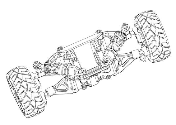
A model rendered with hidden line removal.
The hidden lines/edges can also be optionally drawn using a dimming factor and/or line pattern. This can provide a sense of the inner parts of a model without cluttering the scene. To achieve this effect, enable the visibility of hidden lines, and set the dim factor to a value between 0 and 1, with 1 being completely dimmed:
    mySegmentKey.GetHiddenLineAttributeControl().SetDimFactor(0.75f);
    mySegmentKey.GetHiddenLineAttributeControl().SetVisibility(true);
mySegmentKey.GetHiddenLineAttributeControl().SetDimFactor(0.75f);
mySegmentKey.GetHiddenLineAttributeControl().SetVisibility(true);
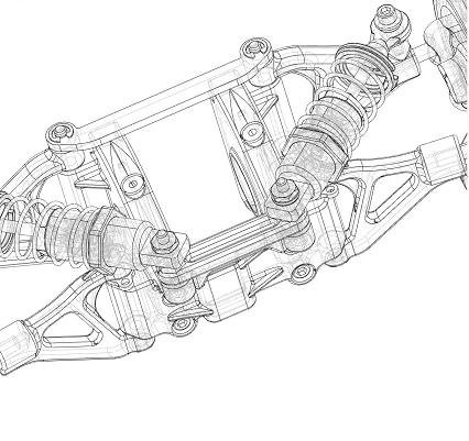
The hidden lines are greyed-out to give an indication of the interior parts of the model assembly.
A summary of all options related to hidden lines can be found in the HPS::HiddenLineAttributeControl section in the API Reference Manual.
“Fake” Hidden Line Removal
If your application is working with large models and you are utilizing a fixed-framerate technique to provide smooth updates regardless of model size, you may wish to employ a ‘fake’ HLR approach when enable HLR for on-screen display. (Per the Reference Manual, FastHiddenLine will provide fast results, but a FastHiddenLine update cannot be interrupted, which is required by the fixed-framerate technique.)
‘Fake’ hidden line involves drawing the scene with the standard ZBuffer algorithm, and using the existing APIs to give an appearnce of HLR by doing the following:
set the model’s face color to the window background color (The face-color will need to be attribute-locked to override any local colors set in the model.)
turn off the visibility of lights
This ‘fake’ HLR approach is not to be confused with one of the official built-in modes of HiddenLine or FastHiddenLine.
Forcing Faces to Be Visible When Using HLR
If the scene contains arrowheads or text, the user will probably want to see filled versions of these objects rather than just their outlines. To force display of faces on a particular segment during an HLR rendering, use the HPS::HiddenLineAttributeControl:
    // faces for this segment are rendered, even when HLR is enabled
    mySegmentKey.GetHiddenLineAttributeControl().SetRenderFaces(true);

    // text for this segment is rendered
    mySegmentKey.GetHiddenLineAttributeControl().SetRenderText(true);
// faces for this segment are rendered, even when HLR is enabled
mySegmentKey.GetHiddenLineAttributeControl().SetRenderFaces(true);

// text for this segment is rendered
mySegmentKey.GetHiddenLineAttributeControl().SetRenderText(true);
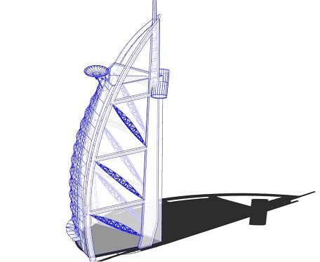
A hybrid rendering of HLR, hidden lines, transparent faces and shadows.
In the above image, faces have been made partly transparent. However, the building still casts a shadow because its faces are still used in shadow calculations. The procedure for generating the image above is demonstrated in the “hidden_line_advanced” sample project.
Bringing 3D Objects to the Front
If you wish to bring a 3D object to the front of a 3D scene, and still want that object to have correctly removed hidden surfaces, then you should set the depth range using the HPS::DrawingAttributeKit. This involves specifying a normalized z-buffer range to compress z-values into a subset of what they otherwise would be. For example, calling:
mySegmentKey.GetDrawingAttributeControl().SetDepthRange(0, 0);
mySegmentKey.GetDrawingAttributeControl().SetDepthRange(0, 0);
…will force all geometry in the affected segment to be drawn into the frontmost z-bucket. Since we’re not allocating any z range at all, this particular depth range would have a side-effect of causing z-fighting amongst any 3D geometry that shares that setting. To get such pieces of geometry to resolve reasonably well against each other, a range of [0, 0.1] usually works well. However, if all the geometry in the segment (or segment tree) with the depth-range setting is 2D (it’s in the same plane), then setting a depth range of [0, 0] would be fine.
