4. Write a CAD Viewer
Welcome to the Mesh Viewer Sample! If you’ve already set up your environment following the Environment Setup guide, learned to load a CAD file using the File-to-File Translation tutorial and How to traverse a model file, you’re now ready for a more hands-on experience.
In this tutorial we will guide you through the process of building your own Mesh Viewer Application from scratch. The Mesh Viewer is a tool for displaying 3D models in a graphical window, and throughout this tutorial, we’ll cover the fundamentals of loading CAD models, traversing meshes, and rendering them using various graphical APIs.
By the end of this tutorial series, you’ll have a solid understanding of how to extract data for visualization using the HOOPS Exchange API, as well as the principles of 3D graphics programming. With your newfound knowledge, you’ll be equipped to create customizable Mesh Viewer applications, ready to integrate with your projects or further customize to suit your needs
This tutorial breaks down the Mesh Viewer Sample in 4 main focus points:
Prerequisites
Before you start this tutorial, make sure your environment is correctly configured. Refer to the Environment Setup Guide for detailed instructions.
To begin development, ensure you have the following:
CMake: If not installed, download and install it from here.
Source Code: The complete source code for this project is available on GitHub. Download and unzip it to your preferred location. Once you have CMake and the source code:
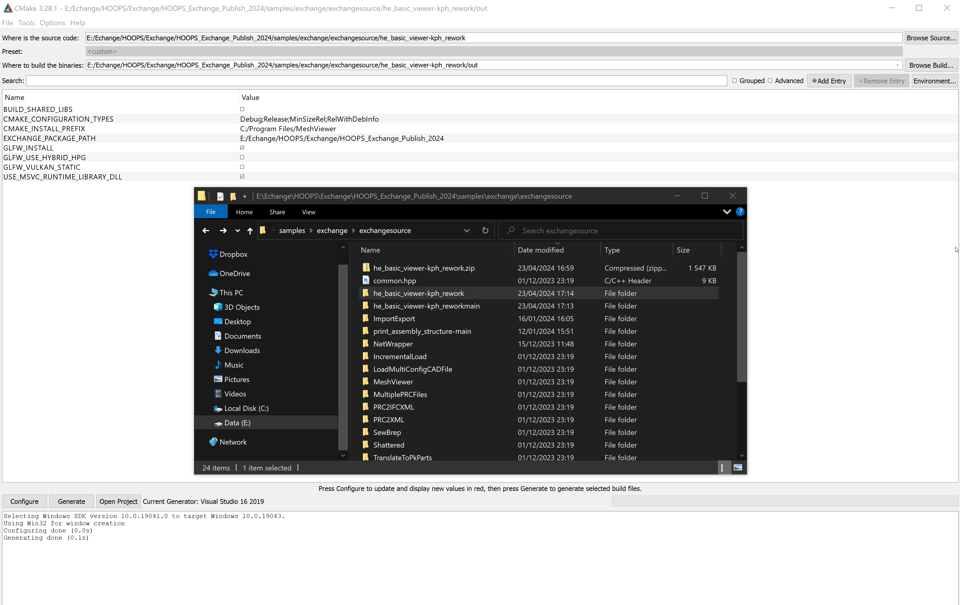
Run CMake.
Similar to the previous Tutorial, set the source directory to the path of the new extracted folder.
Specify the binary directory path for project file generation.
Click the Generate button.
Your project is now configured and ready for compilation and execution.
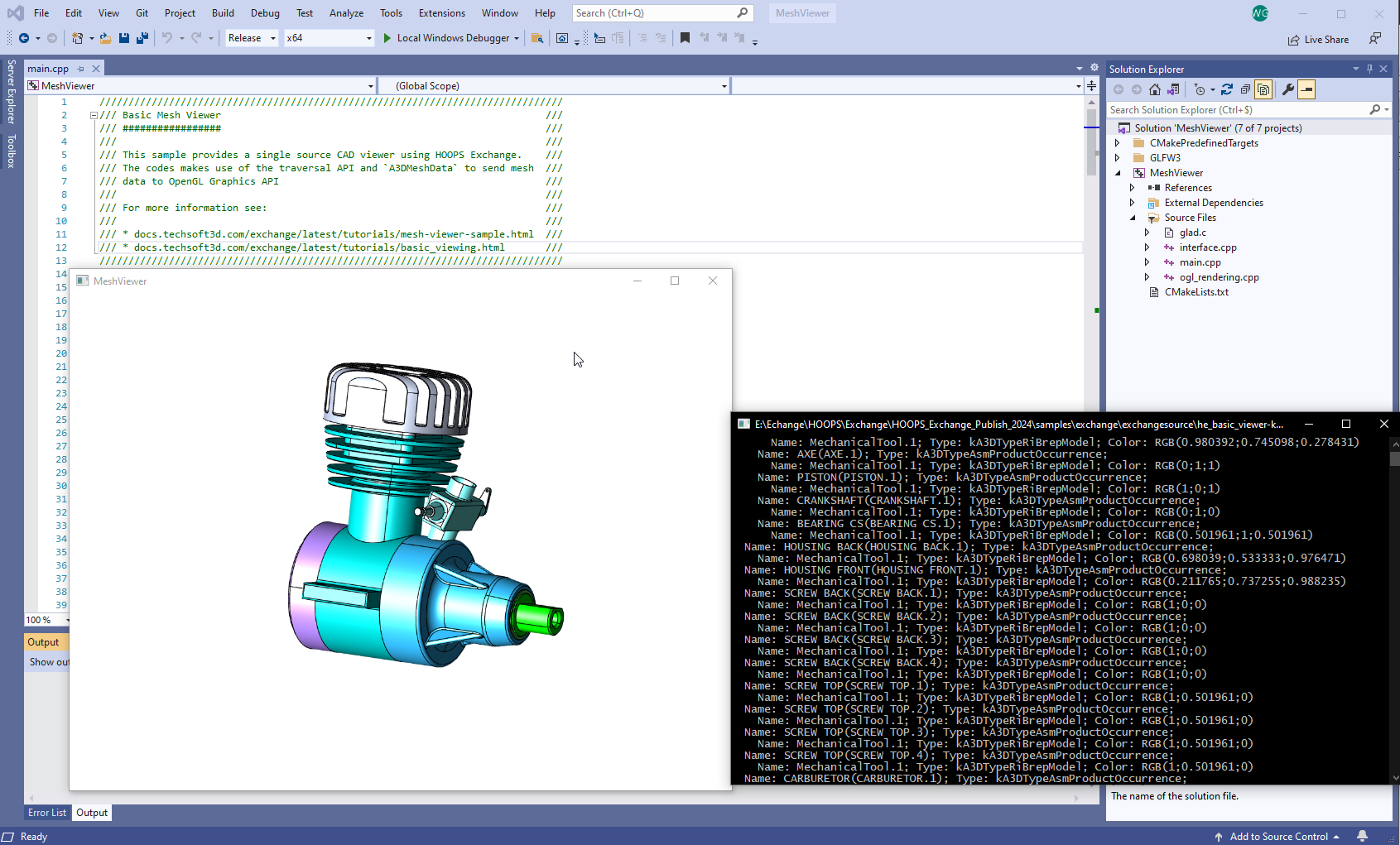
After successfully building and compiling the project, run the generated application. You’ll witness a rotating model displayed in a window:
Load a CAD File
You have learned in the Tutorials Environment Setup and File-to-File Translation how to Configure, Initialize HOOPS Exchange and Load a CAD file.
Here is a quick recap on these functions as implemented in the Mesh Viewer Sample :
In the main() function, the model file is loaded through the A3DSDKHOOPSExchangeLoader helper class.
At the end of the call, model_file contains a valid handle to your loaded CAD file.
Connecting things together, we will then instantiate the A3DTree for our model file and call our traversal function on its root node:
// ...

     /////////////////////////////////////////////////////
     // INITIALIZE HOOPS EXCHANGE AND LOAD THE MODEL FILE.
     A3DSDKHOOPSExchangeLoader he_loader(HE_BINARY_DIRECTORY);
     assert(he_loader.m_eSDKStatus == A3D_SUCCESS);

     A3DImport he_import(HE_DATA_DIRECTORY INPUT_FILE);
     A3DStatus status = he_loader.Import(he_import);
     assert(status == A3D_SUCCESS);
     A3DAsmModelFile* model_file = he_loader.m_psModelFile;

     ////////////////////////////////////////////////////////

     ////////////////////////////////////////////////////////
     // TRAVERSE THE MODEL TREE

     A3DTree* hnd_tree = 0;

     status = A3DTreeCompute(model_file, &hnd_tree, 0);
     assert(status == A3D_SUCCESS);

     A3DTreeNode* hnd_root_node = 0;
     status = A3DTreeGetRootNode(hnd_tree, &hnd_root_node);
     assert(status == A3D_SUCCESS);


     he_traverse_tree(hnd_tree, hnd_root_node, &traverse_data, 0);

     A3DTreeCompute(0, &hnd_tree, 0);
 }

// ...
Extract Mesh data using HOOPS Exchange
Utilize HOOPS Exchange to load CAD models into your application and Implement a traversal algorithm to navigate through the CAD model hierarchy. This traverse function has been covered in the tutorial How to traverse a model file and allows you to access different components of the model:
// ...

     ////////////////////////////////////////////////////////
     // TRAVERSE THE MODEL TREE

     A3DTree* hnd_tree = 0;

     status = A3DTreeCompute(model_file, &hnd_tree, 0);
     assert(status == A3D_SUCCESS);

     A3DTreeNode* hnd_root_node = 0;
     status = A3DTreeGetRootNode(hnd_tree, &hnd_root_node);
     assert(status == A3D_SUCCESS);


     he_traverse_tree(hnd_tree, hnd_root_node, &traverse_data, 0);

     A3DTreeCompute(0, &hnd_tree, 0);
 }

// ...
Traverse the CAD structure and collect data (color, name, entity)
However here in this tutorial we will go deeper, In the traverse function we are adding now a section to access an A3DMeshData when it’s available.
A3DMeshData represents what we need to visualize the entity. Usually, it’s a list of vertices organized as triangular faces and their normals.
In order render the whole model we need to collect all the meshes, their position (the net transformation) and their color.
// ...

// Extract the geometry as an A3DMeshData and collect their position and color to render it
 A3DMeshData mesh_data;
 A3D_INITIALIZE_DATA(A3DMeshData, mesh_data);
 A3DStatus code = A3DTreeNodeGetGeometry(hnd_tree, hnd_node, A3D_TRUE, &mesh_data, 0);

 if (code == A3D_SUCCESS) {
     MeshObject object;
     he_extract_transformation(hnd_node, object.mat_transform_model);
     he_extract_color(hnd_node, object.color);
     object.mesh = mesh_data;
     data_traverse->objects.push_back(object);
 }

// ...
Extract color (advanced)
We have learned how read the color of a node in the previous tutorial, here in addition, we will store the color in our MeshObject structure.
Note that an object can be defined with no color. In this case, we will assign it a default color. In this example we are using a gray color (RGB 0.7;0.7;0.7)
// ...

void he_extract_color(A3DTreeNode* const hnd_node, vec4 color_result)
{
 // Get node's color index
 std::cout << "Color: ";

 A3DGraphStyleData node_style;
 A3D_INITIALIZE_DATA(A3DGraphStyleData, node_style);
 if (A3DTreeNodeGetNetStyle(hnd_node, &node_style) == A3D_SUCCESS)
 {
     A3DGraphRgbColorData color;
     A3D_INITIALIZE_DATA(A3DGraphRgbColorData, color);
     if (A3DGlobalGetGraphRgbColorData(node_style.m_uiRgbColorIndex, &color) == A3D_SUCCESS) {

         SetConsoleTextColorRGB(color.m_dRed, color.m_dGreen, color.m_dBlue);
         std::cout << "RGB(" << color.m_dRed << ";" << color.m_dGreen << ";" << color.m_dBlue << ")";
         ReSetConsoleColorRGB();

         color_result[0] = color.m_dRed;
         color_result[1] = color.m_dGreen;
         color_result[2] = color.m_dBlue;
         color_result[3] = 1.0;

         A3DTreeNodeGetNetStyle(0, &node_style);
     }
     else {
         std::cout << "N/A; "; //default color
         color_result[0] = 0.7;
         color_result[1] = 0.7;
         color_result[2] = 0.7;
         color_result[3] = 1.0;
     }
 }
}

// ...
Extract part position in the 3D space
The position of an object is stored in HOOPS Exchange as A3DMiscTransformation
The function he_extract_transformation gathers this data and converts it to a generic 4*4 matrix stored in the MeshObject structure.
// ...

void he_extract_transformation(A3DTreeNode* const hnd_node, mat4x4 mat_result)
{
 //Extract the net transformation for the node
 A3DMiscTransformation* hnd_net_transform = 0;
 A3DTreeNodeGetNetTransformation(hnd_node, &hnd_net_transform);

 ///then computes a column-major 4x4 transformation matrix out
 /// of an `A3DMiscTransformation` entity.
 /// The result is ready to be send to our graphics API.

 if (hnd_net_transform == 0) {
     mat4x4_identity(mat_result);
 }
 else {
     A3DEEntityType entity_type = kA3DTypeUnknown;
     A3DEntityGetType(hnd_net_transform, &entity_type);
     assert(entity_type == kA3DTypeMiscCartesianTransformation);

     A3DMiscCartesianTransformationData data;
     A3D_INITIALIZE_DATA(A3DMiscCartesianTransformationData, data);
     A3DStatus code = A3DMiscCartesianTransformationGet(hnd_net_transform, &data);
     assert(code == A3D_SUCCESS);
...
}

// ...
Extract B-Rep, Tessellation
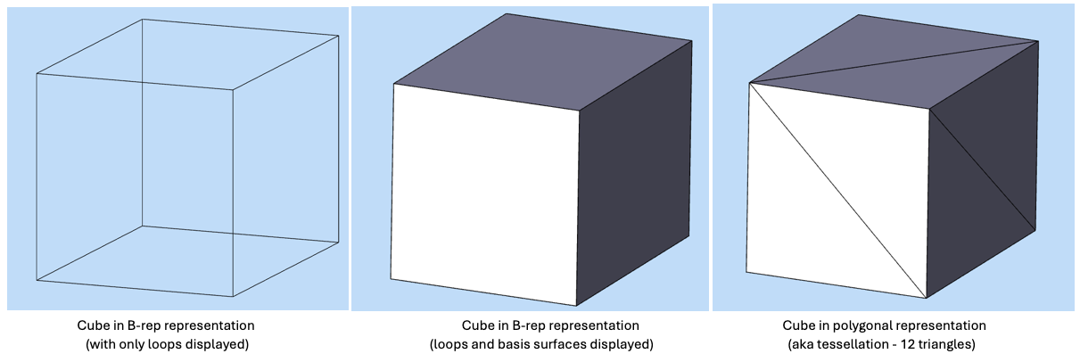
B-Rep (Boundary Representation) and Tessellation are two different methods used in computer graphics and computer-aided design (CAD) to represent geometric shapes, each with its own characteristics and purposes.
- Boundary Representation (B-rep):
B-rep represents objects by explicitly defining their boundaries using surfaces, edges, and vertices.
It provides a precise description of the geometry and topology of the object, allowing for accurate modeling and manipulation.
B-rep is commonly used in CAD systems and solid modeling applications where exact geometry representation is important, such as engineering and architecture.
B-rep models are typically stored as a collection of surfaces (e.g., planes, cylinders, spheres) and their relationships (connectivity, adjacency, etc.).
- Tessellation:
Tessellation, on the other hand, involves approximating curved surfaces with a collection of small, flat polygons (triangles).
It is often used for rendering purposes in computer graphics, as graphics hardware is optimized for processing triangles efficiently.
Tessellation sacrifices some level of precision for computational efficiency and speed in rendering.
Tessellation can be used in applications like video games, computer animation, and visual simulations, where visual fidelity and real-time performance are important.
Tessellation can be generated from B-rep models through a process called tessellation or meshing, where the curved surfaces are approximated with triangular facets.
In summary, B-rep represents objects using explicit boundary definitions (surfaces, edges, vertices), focuses on precise geometric representation suitable for design and engineering tasks whereas tessellation represents objects using a mesh of small polygons (triangles) and prioritizes computational efficiency and speed in rendering for visual applications.
More details related to B-Rep & Tessellation data and how to traverse topology information using HOOPS Exchange are available in a section of our Programming Guide : Geometry.
In the Mesh Viewer Sample we use a simplified function to quickly traverse the Geometry that will be rendered by the graphic engine, here we use the function A3DTreeNodeGetGeometry:
// ...

// Extract the geometry as an A3DMeshData and collect their position and color to render it
 A3DMeshData mesh_data;
 A3D_INITIALIZE_DATA(A3DMeshData, mesh_data);
 A3DStatus code = A3DTreeNodeGetGeometry(hnd_tree, hnd_node, A3D_TRUE, &mesh_data, 0);

 if (code == A3D_SUCCESS) {
     MeshObject object;
     he_extract_position(hnd_node, object.matrix_position);
     he_extract_color(hnd_node, object.color);
     object.mesh = mesh_data;
     traverse_data->objects.push_back(object);
 }

// ...
Interface to store data
Now that we have collected all the data from the CAD file we will render them in the graphics engine. All graphics engines have their own way of handling data, but they commonly require three main components to display an object:
A mesh description, which is a collection of faces and their normals (direction of the outbound face).
A position in 3D space.
A color or material.
Our interface will utilize two structures to store the objects we will render in the scene.
The
MeshObjectstructure is used to store a single object. The data for this structure will be gathered from HOOPS ExchangeA3DMeshDatafunction.
// ...

struct MeshObject {
 mat4x4  matrix_position;  // Position of the object.
 A3DMeshData mesh;
 vec4 color;
};

// ...
In CAD we often deal with complex objects that are made of multiple objects. We use the structure
TraverseDatato hold the collection ofMeshObjectrepresenting the models.
// ...

struct TraverseData {
std::vector<MeshObject> objects; // All GPU objects in the scene.
};

// ...
This interface will be used to send the data to a graphics engine. Let’s learn how to write the functions that convert the data to the corresponding graphics engine.
Send to Graphics Engine
Now that we have collected and stored all the data needed to render the model on a graphic display, we can send them to a rendering engine. In this tutorial we are sending our data to OpenGL through the interface we created.
After calling the traverse tree function and filling the TraverseData structure, simply call send_to_openGL(traverse_data).
- The code that is called then is specific to an OpenGL integration :
It initializes an OpenGL context and a basic 3D scene.
It uses the
TraverseDatato create buffers that are sent to the GPU.
The file ogl_rendering.cpp contains the code for simple shaders displaying the object with the correct positions and colors.
To send our A3DMeshData to the graphics API, simply use the ogl_mesh_data_to_rendering() function.
This will associate the underlying A3DEntity of a node to the graphics identity returned by ogl_mesh_data_to_rendering(). It generates a GPU object for every renderable A3DEntity.
Don’t hesitate to test the Mesh Viewer Sample with another CAD file or setting of your choice.
Coming soon…
Coming soon…
Coming soon…
Performance Considerations
For tutorial purposes, there is no optimization in the graphic pipeline.
However The samples MeshViewer from the official HOOPS Exchange package shows a more advance implementation of a Viewer, including optimization such as using instantiation of objects.
Conclusion
You have now acquired solid knowledge required to use HOOPS Exchange and to connect it with a Graphics Engine.
HOOPS Exchange can do more, the API offers also a set of geometric functions for querying your models and adapting the geometry to meet your requirements. The API can generate various types of Tessellation, repair, sew, heal inconsistent geometries, adapt B-rep definition & surfaces for reuse by different modelers. Additionally, it can evaluate and project points on surfaces, compute Physical Properties, and can be paired with third-party libraries such as geometric kernels (Parasolid, ACIS, OpenCascade) or Mesh Repairs API (Polygonica) to enhance your market needs and workflow.
The HOOPS Exchange package gives you access to a set of Samples Code demonstrating these functionalities.
If you are ready to discover more about HOOPS Exchange capabilities, jump right away to the Programming Guide and API References sections of our documentation.
