
HOOPS Parasolid Demo Viewer
The HOOPS Parasolid Demonstration Viewer (HPDV) is a Windows application which demonstrates HOOPS Visualize Desktop, HOOPS Exchange, and Parasolid working together in a single application. All CAD data is read through HOOPS Exchange and then mapped to Parasolid using the HOOPS Exchange Parasolid integration. Significant efforts are made to ensure the imported model is of the highest quality and users can control these import parameters on import. Furthermore, any Parasolid-based format (NX, SolidWorks, Solid Edge, or XT) is imported without any modification to the underlying topology or geometry. Advanced geometric query of the model is provided in the HPDV and is done via the Parasolid API. Users can export the models to XT if they wish to test the quality of the imported models in their own application.
Licensing
The HOOPS Parasolid Demo Viewer requires a valid license key to run. HPDV is packaged with a trial license which allows customers to run the program for 30 days. When using a trial license, a message appears at startup, letting you know how many days you have left before the trial expires. The trial license can be converted to a permanent license by requesting a permanent license from Tech Soft 3D support.
Opening a File
There are three ways to open a file:
1. By clicking on File/Open or pressing CTRL+O. Doing this will cause the following dialog to appear:
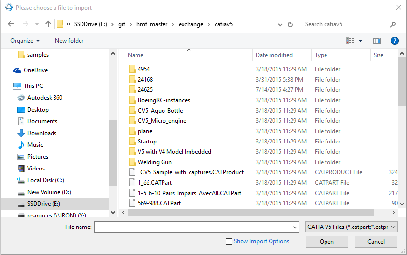
If you check the ‘Show Import Options’ check box, and then open a file, a dialog appears which allows you to specify import options for the file that was selected. See the next subsection for an explanation on import options. Clicking ‘Open’ without checking ‘Show Import Options’ will import the selected file with the import options which were specified last (of the default ones, if they were never specified).
2. By dragging and dropping a file. When dragging and dropping a file, it is automatically opened using the import options the user last specified.
3. By choosing a file from the Recent Document list. When opening a file through the Recent Document list it will be imported using the import options the user last specified.
Import Options
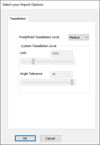
If you are loading a Parasolid file, the loading options include the following:
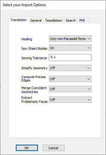
If you are loading a non-Parasolid file, the HPDV will perform a translation. In this case, there are many more options to consider. The options dialog will have General, Tessellation, Search, and PMI tabs, plus a tab for the Translation options, plus a format specific tab. For example, if you load a CATIA V5 file, that file will need to be translated, so this is the dialog you will see:
The “General” tab allows you to select which entites are imported: solids, surfaces, attributes, and construction entities.
The “Translation” tab allows you to control healing and sewing operations. It can also be used to simplify the geometry or merge the topological entities. More details are provided below for each option.
- Sewing: Model sewing can be enabled or disabled. When enabled, a you can set the sewing tolerance.
- Healing: This option is used to heal Parasolid models. It primarily affects the number of PK body check issues, removes self-intersection, degeneracies, and overlapping tolerances. Three values can be defined: On, Off, or “Only non-Parasolid format”, which will enable healing for data coming from Parasolid-based files.
- Simplify Geometry: This option transforms surfaces and curves to analytics (lines, circles, planes, cylinders, etc.)
- Merge Coincident Geometries: This option merges surfaces and curves where it is feasible to do so. For instance, it can typically merge two half cylinders into one cylinder.
- Compute Precise Edge: This allows you to transform parametric 2D curves into 3D trimming curves that have a smaller tolerance.
- Extract Problematic Faces: Isolates faces with a PK_FACE_state_bad_face_face_c issue in a particular shell.
The “Tessellation” tab allows the user to specify the level of tessellation from 5 preset levels, or to choose custom tessellation values. A higher tessellation level will result in a more detailed model at the cost of a slower import.
The “Search” tab specifies which folders Exchange should search when looking for file references.
The “PMI” tab specifies whether PMI should be imported, its color, and a backup font to be used in case the original font cannot be found.
The “CatiaV5” tab has V5 specific caching options, and will only appear when importing CatiaV5 files.
These options, and the folder from which the user completes the import, will be saved to a preference file. They will be the same from one import to the next, and from one application run to the next.
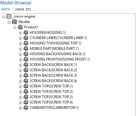
Incremental Loading
SolidWorks, NX (Unigraphics), Creo (Pro/E), and CATIA V5 files may be loaded incrementally. This means that only the assembly tree is loaded into memory, but geometry is not. Specific parts may then be loaded using the Model Browser. Incremental loading saves time and memory because only the model skeleton is loaded. To enable incremental load, make sure the “Loading Mode” drop-down is set to “Incremental” in the load dialog.
This is what the Model Browser will look like after an incremental load:
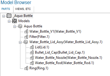
At this point, the user can select which of the product occurrences listed in the Model Browser to load. To do so, right-click the desired product occurrence and choose ‘Load’. Loaded product occurrences can also be unloaded, by following the same process and selecting ‘Unload’. Note that only the geometry on leaf product occurrences will be loaded.
Multi Function Operator
The default operator for the HOOPS Parasolid Demo Viewer allows the user to orbit, pan, zoom, zoom to extents, and select.
- Orbiting around the Camera target is activated with the left mouse button. Alternatively, you can orbit around the position under the mouse cursor by pressing the middle mouse button (as long as geometry is present underneath the mouse cursor).
- Panning is activated with the right mouse button.
- Zooming is activated through the mouse wheel.
- Zooming to extent is activated by a double left click on a portion of the main window not occupied by the model.
- Selection happens when the left mouse button goes up, if the location at which it goes up matches the location at which it went down.
- Hold shift to get dynamic highlighting
- Press ‘H’ to hide
- CTRL-A selects everything
After switching operators, the user can go back to this operator by clicking on Orbit, on the HOME tab.
The selection operator can select both faces and edges. Since selecting edges is always more difficult than selecting faces, the operator is designed to be biased towards selecting edges. Therefore, if the user performs a selection close enough to an edge, the edge will be selected even though the actual selection event happened on a face.
It is possible to restrict the selection operator to only selecting faces, or only selecting edges, by using the Selection Mode drop down menu at the far right of the HOME tab, pictured below:
Selection
Hierarchical Selection
The default selection operator performs hierarchical selection. This means that if the user selects a component which is already selected, its owner will be selected instead. This creates a situation where selecting the same element over and over, moves the selection up through the hierarchy of components until the root model file is reached.
During the process of selection, physical properties are collected for the selected objects and are displayed on the Property Pane, and finally the selected geometry is highlighted.
Multiple Selection
There are three ways of selecting multiple objects in the scene.
- By using the default operator, and selecting objects while holding down the CTRL button.
- By using the Area Select operator and dragging the mouse (an overlaid rectangle will be drawn to show the selection area).
- By selecting items in the Model Browser while holding down the CTRL button.
If an Isolate operation is carried out while multiple objects are selected, all the selected objects will be shown while the rest of the model will be hidden. The camera will be smoothly reset to a bounding box which fits all the isolated objects.
If Hide operation is carried out while multiple objects are selected, all the selected objects will be hidden.
When selecting multiple objects, the property window will display properties for the last object you selected.
Some items (like views) which are present in the Model Browser cannot be selected, and therefore cannot be multi-selected either.
Highlighting
Highlighting happens when objects are selected through the default operator or the Area Select operator. The default highlight color is green. Geometry will be highlighted in orange if its color is close to green, so that the user always has a clear indication of what is highlighted.
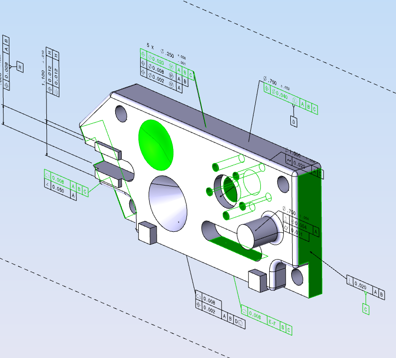
When a face is highlighted the edges related to that face are also automatically highlighted, and a depth range effect is applied to them, so that they are always visible through the model, as shown below:
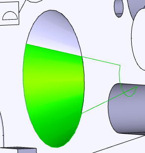
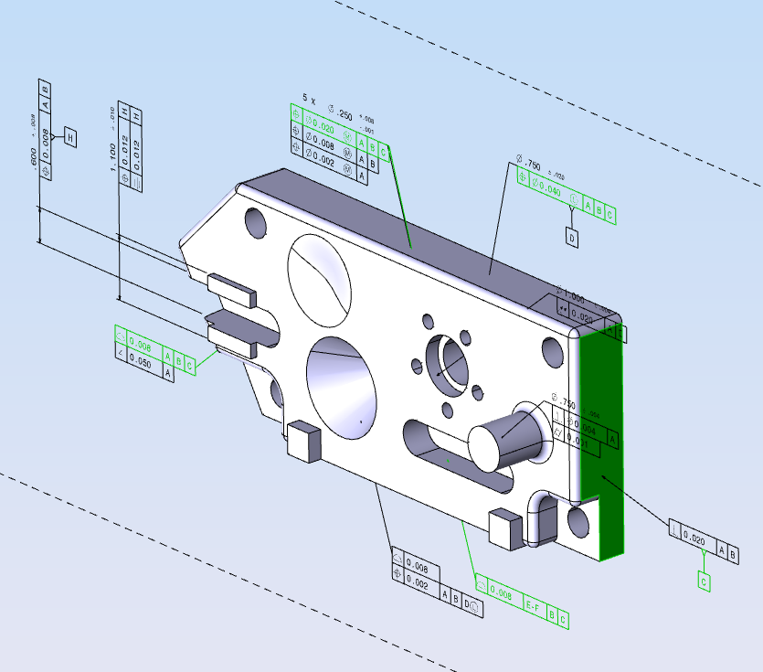
If a face has PMI attached to it, that piece of PMI will also be highlighted when the face is selected. Conversely, when highlighting a Datum (a particular type of PMI used to label a surface), its related face will be highlighted.
Clicking on the same Datum twice in a row, highlights all other pieces of PMI which also reference the same surface.
Clicking on the same Datum a third time in a row, highlights all other pieces of PMI which reference the same surface, and all the surfaces referenced by these other PMI. This is shows in the table below (click images to enlarge):
| Selecting in C | Selecting in C twice | Selecting in C thrice |
|---|---|---|
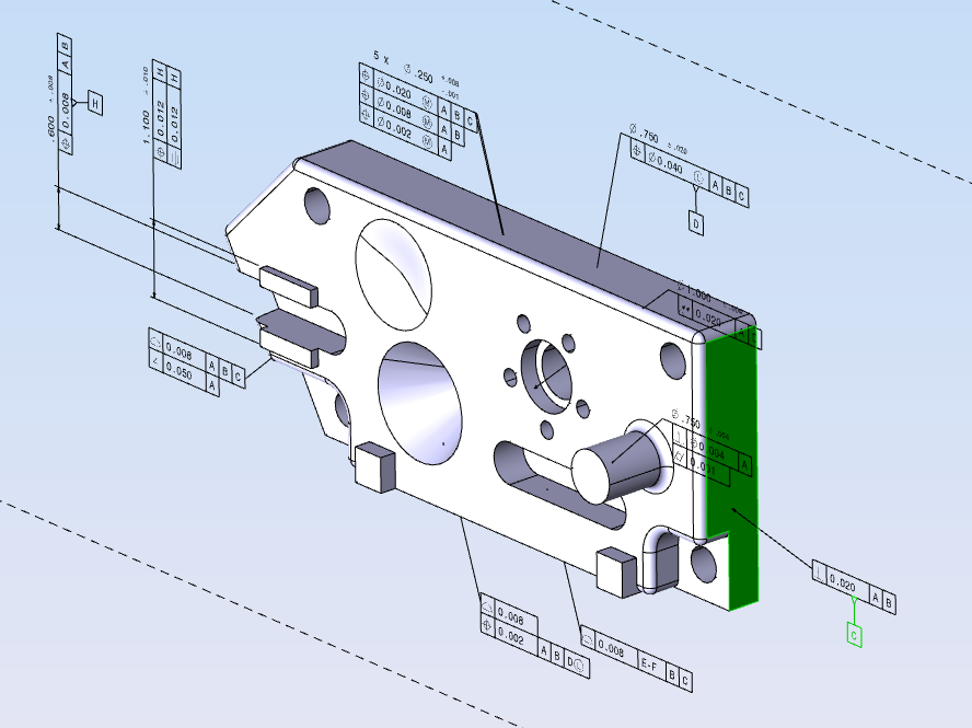
|
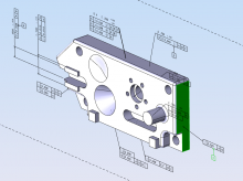
|
|
|
|
|
|

|
Dynamic Hghlighting
Dynamic highlighting is a method of highlighting where objects are highlighting simply by moving the mouse over the object without clicking. This mode is activated by holding down the shift button and moving the mouse around. No buttons clicks are necessary. During dynamic highlighting, edges cannot be selected.
Model Browser
The Model Browser is used to quickly select components and to inspect the component hierarchy. The model browser is constituted of three panes, with the third pane only shown under certain conditions. Here is an explanation of each pane:
Model Browser Pane
This is the first of the three panes. When the application starts it is shown on the left, on top of the other two panes. It contains the model component hierarchy. Clicking on an item will change its text to bold and will change the item background to blue, so users can tell which item is selected. If the selected item is a view, it is activated with a smooth camera change. If the item is a component, it is highlighted and its properties are shown on the property pane.
Right-clicking on certain components from the model browser will cause a context menu to appear. The context menu will give the user the option to either isolate or show a component, based on its current visibility state (hidden components can be shown, shown components can be isolated). The icon and text representing an item should be grayed out when the item is hidden.
Views Pane
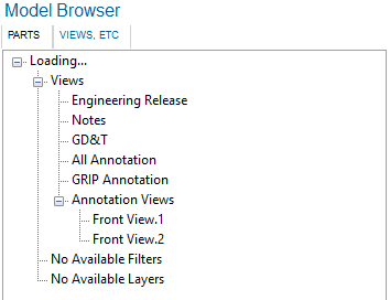
The Views pane collects the Views, Filters and Layers for a model. The views are further divided among Annotation and non-Annotation Views. Clicking on a view will cause it to become active, smoothly changing the camera to fit the new view.
Filters and layers can be toggled by clicking on them. Note that activating a filter or a layer can, in turn activate other filters or layers. Filters and layers which are active are shown in bold. Not every model has views, filters or layers. In the case of a model lacking filters, for example, the string ‘No Available Filters’ will be shown in this pane.
Configuration Pane
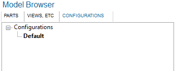
The Configuration Pane only appears if the model you have loaded contains more than one configuration. Like the name implies, it lists all the available configuration, with the active one displayed in bold. Double clicking on a configuration other than the one currently active causes that configuration to be loaded, which necessitates a full import.
Switching between loaded models will cause the different panes of the Model Browser to update as needed, with the Configuration Pane dynamically appearing and disappearing based on the tab which is currently active. If you reorganize the tabs so that you can see multiple models at once (for example by dragging a tab so that you have two side by side), the Model Browser will reflect the state of the active tab, of which there can only be one at any give time, and is the last tab you have interacted with.
Property Pane
The Property Pane is used to inspect the properties for the selected component. It is divided into four sections, explained below:
- File properties
File properties include the total load time, broken down into multiple stages. The number and type of stages shown varies, based on whether the model comes from a non-Parasolid-based CAD format, a Parasolid-based CAD format, or is simply a Parasolid file.
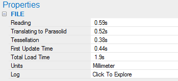
In the case of a non-Parasolid-based CAD format, these stages are: Reading, Translating to Parasolid, Tessellation, First Update Time, Total Load Time, Units, and Log. Reading represents the time spent in HOOPS Exchange extracting data from the CAD file(s). Translating to Parasolid represents time spent in HOOPS Exchange and Parasolid Bodyshop translating the BRep data to Parasolid. This time is mostly affected by what translation options are specified during import. Tessellation represents the time spent building the scene graph and generating the tessellation from the Parasolid data. First Update Time represents the time spent by HOOPS Visualize Desktop populating display lists, creating a static model, and issuing the first update. Total Load Time is a sum of the previous times. Units shows the units of the CAD file. Log provides a button that can be clicked on to open a window displaying the import and translation log generated by Exchange.
The file properties pane for non-Parasolid files:
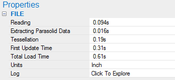
In the case of a Parasolid-based CAD format, these stages are: Reading, Extracting Parasolid Data, Tessellation, First Update Time, Total Load Time, Units, and Log. These values represent the same information as when a non-Parasolid-based CAD file is imported, with the exception of Extracting Parasolid Data in place of Translating to Parasolid. Extracting Parasolid Data signifies that no translation is taking place, rather Parasolid data is simply being extracted from the CAD file. This time may additionally include time spent healing or modifying the Parasolid data depending on the translation options specified during import.
The file properties pane for Parasolid-based files:
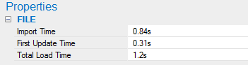
In the case of a native Parasolid file, these stages are: Import Time, First Update Time, and Total Load Time. Import Time represents the time spent reading the data from the file and the generation of the scene graph and tessellation. First Update Time represents the time spent by HOOPS Visualize Desktop populating display lists, creating a static model, and issuing the first update. Total Load Time is a sum of the previous times.
The file properties pane for native Parasolid files:
- General properties
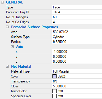
General Properties include geometric properties related to the face or edge which was selected. The property displayed change based on the type of component which is selected. The ‘Net Material’ subsection is populated from data obtained from the scene graph. All the other properties are populated by querying Parasolid directly. Some properties, like ‘No. of Triangles’ and ‘No. of Co-Edges’, which can be time intensive to calculate, are cached into the scene graph, so that repeated requests for properties from the same components should be faster than the original query. When selecting an Edge, the properties shown include its length, and the properties of its Co-Edges, if available. Selecting a Face, shows its area, the number of triangles and the number of edges used to draw it. Additionally data for its underlying surface and its material information are shown. Selecting a Body, shows its surface area, volume and center of gravity. The number of edges, faces and triangles making up the Body is shown, together with its material info. If the Body is affected by transformations other than the Identity matrix, those transformations can be explored from the ‘Local Transformation’ and ‘Net Transformation’ sub-properties. When clicking on their respective buttons, a separate dialog opens allowing the user to inspect the relevant matrix.
- Metadata
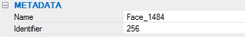
The Metadata section is a list of some of the metadata (or attributes) associated with the selected component. For a Parasolid component this would include the name, identifier, and layer (if present).
- PMI Properties
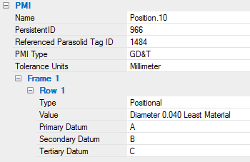
The PMI section provides the semantic meaning of the selected PMI. This data is only available if a PMI is selected and the model was imported with BRep When this happens the contents of the General Property section is populated with information taken from the geometry which is referenced by the selected PMI.
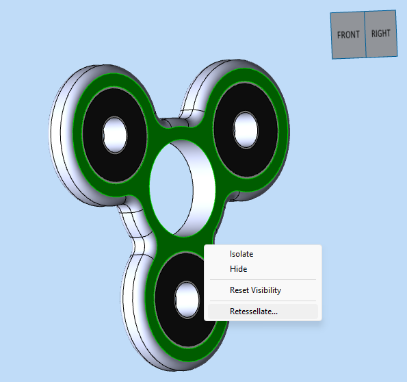
Isolating, Hiding, and Retessellating Geometry
Geometry can be isolated or hidden in two ways:
- Through the context menu on the Model Browser (right-click on an item)
- Through the context menu on the main 3D window (right-click on the geometry and choose isolate, or right-click anywhere and choose isolate to isolate the currently selected geometry).
Once something is isolated or hidden, the performance will usually suffer from a downgrade. It is important to track the isolated performance over different releases of the HOOPS Parasolid Demo Viewer.
Once an object has been isolated or hidden, it should still be selectable, while everything else should be non selectable and invisible. The camera should smoothly change to fit the remaining geometry.
There are two ways to undo an Isolate or Hide operation:
- Right-click on the main 3D window and choose ‘Show All’
- Right-click on a hidden Model Browser item and choose ‘Show’
H-to-Hide
Pressing ‘H’ on the keyboard will turn the geometry under the mouse pointer transparent, and change its line color to white. This will also make the hidden geometry non selectable, so that it is possible to select THROUGH an object that has been hidden by pressing H.
Note that it is not possible to use this functionality while in isolate mode.
It is possible to hide multiple pieces of geometry at the same time through this functionality. All the geometry which has been hidden through pressing H will become visible again upon clicking on the background window.
Retessellating
The “Retessellate” context menu option allows you to retessellate a model according to your needs.
A higher tessellation will improve the smoothness and detail of a model at the cost of performance. It is especially noticeable in curved or rounded areas. HDV has a few different pre-configured tessellation levels to choose from, or you may set a custom level:
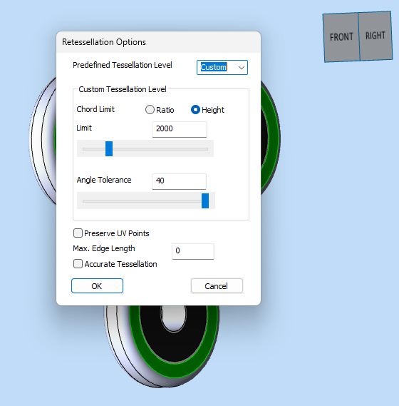
Retessellation is not available for all geometry types.
Exporting Files
The HPDV can export to the .XT file format. A file export operation can be initiated by pressing CTRL+S or by pressing File/Export. Once one of those two actions has been carried out, the following dialog will appear:
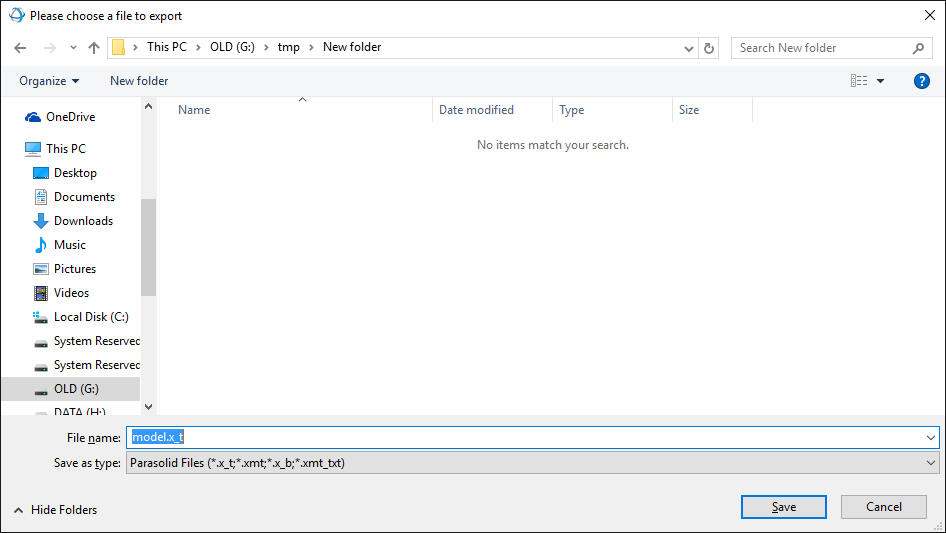
Once an export operation starts, it cannot be canceled by the user.
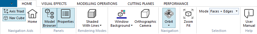
Ribbon Explanation
This is a breakdown of the functions exposed through the Ribbon, and their description, left to right. These settings are handled on a per-tab basis.
Home ribbon
| Axis triad | Toggles axis triad on and off. ON by default. |
| Nav cube | Toggles navigation cube on and off. ON by default. |
| Home | Smoothly activates the default view for Exchange files. For non-Exchange files it zooms to extent. |
| Model browser | Toggles visibility of the Model Browser panes on and off. ON by default. |
| Properties | Toggles visibility of the Properties pane on and off. ON by default. |
| Rendering modes | Sets the rendering mode. Choices are ‘shaded’, ‘shaded with lines’, ‘tessellated’, ‘hidden line’, and ‘wireframe’. |
| Window background | Changes the window background color. This setting applies to the current tab and to all the tabs which will be then opened. The color setting is saved to the preference file, and will be restored to your last choice the next time you run the application. Clicking on the bottom part of the button allows the user to choose from a color palette or to revert to the default color. |
| Orthographic/Perspective camera | Changes the camera projection. The text of the button represents the current camera projection. By default an orthographic projection is used, except for IFC files, which are loaded with a perspective camera. |
| Operators | Allows you to choose the current operator. Default is ‘Orbit’, but you may also choose from ‘Zoom Area’, ‘Turntable’, ‘Fly’, ‘Zoom Fit’, and ‘Point’. |
| Selection mode | Switches between face selection, edge selection or face+edge selection. Defaults to face+edge selection. |
| Repair Mesh | Reorganizes mesh data to help remove visual anomolies. Information about removing T-junctions is available here. |
Rendering Modes Explanations
Shaded: Sets the rendering mode to Phong, turns silhouette edges off. If the loaded model is an IFC model, it turns off hard edges and perimeter edges, and turns line visibility on.
Shaded With Lines: Sets the rendering mode to Phong With Lines, turns silhouette edges off. For IFC models it turns hard edges and perimeter edges on.
Tessellated: Sets the rendering mode to Flat, turns silhouette edges off. Turns edge visibility ON. For IFC models it turns hard edges and perimeter edges on.
Hidden Line: Sets the rendering mode to Fast Hidden Line. Turns edge visibility OFF, and silhouette edges ON. If fixed frame rate is enabled, it disables it and prevents the user from enabling it until when the rendering mode is changed. For IFC models it turns hard edges and perimeter edges on.
Wireframe: Sets the rendering mode to Wireframe, turns silhouette edges off. Turns edge and face visibility OFF. For IFC models it turns hard edges and perimeter edges on.
Operator Explanations
Zoom Area: Click and drag the mouse to perform a zoom based on that area.
Turntable: The turntable operator is an operator which allows the user to orbit the camera along a specific axis. This operator works for both mouse- and touch-driven devices.
Fly: The fly operator is an operator which allows the user to accurately move the camera around the scene. This operator works for both mouse- and touch-driven devices.
Zoom Fit: Zoom fit operator.
Point: Custom operator which allows the user to both select and area select.
Visual Effects Ribbon
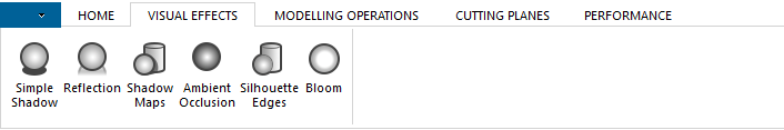
| Button name | Description |
|---|---|
| Bloom | Toggles the bloom effect on/off. OFF by default. |
| Simple shadow | Toggles simple shadows on/off. OFF by default |
| Shadow maps | Toggles shadow maps on/off. OFF by default. When enabled, the light in the scene is deleted and replaced with three fixed lights of smaller intensity. When shadow maps are enabled the lights do not follow the camera. Disabling shadow maps deletes the three static lights and reintroduces the previous light, which follows the camera. |
| Reflection | Toggles the reflection plane on/off. OFF by default. |
| Ambient occlusion | Toggles ambient occlusion. OFF by default. |
| Silhouette edges | Toggles silhouette edges on/off. OFF by default. Silhouette Edges are activated automatically whenever the user switches to Hidden Line rendering mode. Since this is done automatically the button on the ribbon does not change states. This automatic action is reverted when the user switches from Hidden Line to a different rendering option. |
Modelling Operations Ribbon
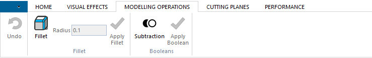
| Field/Button name | Description |
|---|---|
| Undo | Undoes the last modelling operation. |
| Fillet | Starts a fillet operation. Clicking this button during a pending fillet operation will return the user to the Orbit operator without committing the fillet. |
| Radius | Specifies the radius of the fillet in mm. Must be specified before the fillet operation has started. |
| Subtraction | Toggles boolean subtraction on and off. |
| Apply Boolean | Applies the Boolean operation to the selected bodies. |
Creating Fillets
After a model is loaded, click on the Fillet button to start the Fillet operator. While in fillet mode:
- Edges will be highlighted when you mouse over them.
- Clicking on an edge selects it.
- Clicking on a selected edge deselects it.
- Clicking on the background de-select all edges.
- Orbit / Pan / Zoom will still be enabled.
After you have selected the edges you want to fillet, click the Apply Fillet button to apply the fillet to the model with the specified radius.
If the operation succeeds you will see your outcome on screen. If the operation does not succeed, a pop-up will appear that explains which Parasolid function failed and why.
Many edges cannot be blended because of surrounding topology, or because the radius specified is too large or small.
Unsuccessful blends are automatically undone and the state of Parasolid is restored to its state before the fillet was attempted.
The undo button will become active when you have made a successful blend. Clicking it will undo the most recent blends in order.
Boolean Operations
A boolean subtraction is an operation involving two bodies: a target and a tool. The result of the operation is that the parts of the target body which overlap with the tool are deleted from it. At the end of the operation the tool body is deleted.
Example: You have two bodies: a cube and a cylinder. The cylinder intersects the cube at its center.
You choose the cube as the target and the cube as the tool of the boolean subtraction. After the boolean subtraction takes place, the cylinder is gone, and the cube now has a cylindrical hole in it where the cylinder used to be.
How to Use the Boolean Operator
- Load a file in the HOOPS Parasolid Demo Viewer.
- Add a second file to the same scene (using the Add… command).
- The objects from both files should overlap.
- In the Modelling Operation tab choose the Boolean Subtraction operator.
- The first click will select the Target of the Boolean Subtraction. The target will be highlighted in green, and it will become semi-transparent. Clicking on the target again will de-select it.
- The next click (after a target is selected), will select the Tool for the Boolean subtraction. The tool will be highlighted in orange. Clicking on the tool again will de-select it.
- After both a target and a tool have been selected, press ‘Apply Boolean’ and the boolean operation will take place.
- You should be able to select the result of the boolean operation and to query its properties. The tool should be gone both from the scene and the Model Browser.
At any point before you click ‘Apply Boolean’ you can cancel the boolean operation by clicking on the ‘Boolean Subtraction’ perator again. After a boolean operation is complete, you can click Undo to return to the previous state.
Current limitations
When tessellation-only geometry is translated to Parasolid, color information is lost. Since the results of booleans between B-rep geometry and non-B-rep geometry is always non-B-rep geometry, the demo would result in the boolean having the default HOOPS Visualize Desktop color, instead of inheriting its correct color.
Cutting Planes Ribbon
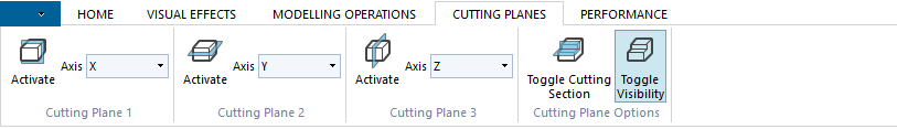
| Button name | Description |
|---|---|
| Cutting plane 1 | Inserts a cutting plane with a normal along the indicated axis. |
| Cutting plane 2 | Inserts a cutting plane with a normal along the indicated axis. |
| Cutting plane 3 | Inserts a cutting plane with a normal along the indicated axis. |
| Toggle Cutting Section | If OFF, when clicked it collects the active cutting planes into a single cutting sections. If ON, when clicked it splits the current cutting section into individual cutting planes. By default planes are not collected into a cutting section. |
| Toggle visibility | Toggles the visibility of the geometry representing the planes on/off. ON by default. |
NOTE: The possible choices for cutting plane axis are: X, Y, Z, and From Face. Selecting ‘From Face’ and then activating the cutting plane changes the mode of the application. At this point moving the mouse on the scene will display an indicator of where the place will be positioned. Move the mouse pointer to the desired position and left-click to position the cutting plane.
Performance Ribbon
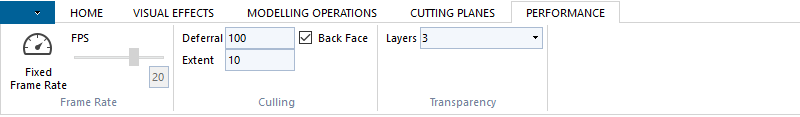
| Button name | Description |
|---|---|
| Fixed Frame Rate | Toggles Fixed Frame Rate mode on/off. OFF by default. It is not possible to turn fixed frame rate on while in the Hidden Line rendering mode. The frame rate target can be set through the slider once Fixed Frame Rate mode has been activated. The slider can range is [0-30], with 0 disabling Fixed Frame Rate mode. While Fixed Frame Rate is active, any transparent geometry is rendered using screendoor while the camera is moved. Moving to and from Fixed Frame Rate will cause the static model to be regenerated. A dialog appears during the regeneration, since this operation can take up noticeable time with large models. |
| Culling options | This sections allows the user to change the default culling options. |
Release Notes
HPDV 2024.8.0
New Experimental Feature:
- Remove T-Junction [Experimental] A new toolbar menu button is available in the HPDV toolbar to remove T-junctions from tessellated models. For more information, please refer to link here.
HOOPS Parasolid Demo Viewer 2024.8.0 updates component libraries to version 2024.8.0.
HPDV 2024
HOOPS Parasolid Demo Viewer 2024 updates component libraries to version 2024.
HPDV 2023 SP1
Introducing our newly enhanced search experience, which includes the following new features:
- Exact match: Search for exact matches only by wrapping the search term - or phrase - in quotation marks.
- Fuzzy search: Search results now appear for the closest matches even if no exact matches are found.
- Result filtering: Narrow your search results by section.
HOOPS Parasolid Demo Viewer 2023 SP1 updates component libraries to version 2023 SP1.
HPDV 2023 U1
HOOPS Parasolid Demo Viewer 2023 U1 updates component libraries to version 2023 U1.
HPDV 2023
HOOPS Parasolid Demo Viewer 2023 updates component libraries to version 2023.
HPDV 2022
HOOPS Parasolid Demo Viewer 2022 updates component libraries to version 2022.
HPDV 2021
HOOPS Parasolid Demo Viewer 2021 updates component libraries to version 2021.
HPDV 2020 SP2
HOOPS Parasolid Demo Viewer SP2 is a bug fix release only.
HPDV 2020 SP1
HOOPS Parasolid Demo Viewer SP1 is a bug fix release only.
HPDV 2020
Functional Changes
Multiprocess loading. The multiprocess loading option has been removed.
HDV 2019 SP2
Functional Changes
Content menu. The context menu option “Show All” has been changed to “Reset Visibility”.
HPDV 2019 SP1 U1
HOOPS Parasolid Demo Viewer 2019 SP1 U1 is a bug fix release only.
HPDV 2019 SP1
Functional Changes
HandlesOperator. The HandlesOperator translation function now appends transforms instead of applying a new transform after each action.
HPDV 2019
Enhancements
Handles operator. A “handles” operator has been added. To use the handles operator, load a model and double click on a part. The handles will appear, and you will be able to rotate the model, translate along an axis, and translate along a plane. Once you are satisfied with the position of the geometry you moved, click once on the background to finalize the movement operation and dismiss the handles.
Any changes you make will be reflected in the component structure. Saving out and reloading a model will preserve the transformations you have applied.
