
Advanced Functions
This section outlines several high-level operations provided by the HOOPS Exchange API.
Contents
Computing Lengths
In HOOPS Exchange, all lines, edges, and curves have an associated curve, whose base type is A3DCrvBase.
This geometry always exists as part of a representation item.
Recall that representation items may have many different types, thus, it is necessary to check the type before operating on it.
In this case, we’ll examine a tessellated entity of type kA3DTypeRiCurve.
Computing the curve length requires drilling down a few levels in order to get the necessary parameters:
A3DEEntityType eType;
A3DEntityGetType(repItem, &eType);

if (eType == kA3DTypeRiCurve)
{
   A3DRiCurveData riCurveData = A3D_MAKE_DATA(A3DRiCurveData);
   A3DRiCurveGet((A3DRiCurve*) repItem, &riCurveData);

   A3DTopoSingleWireBody* tswb = riCurveData.m_pBody;
   A3DTopoSingleWireBodyData tswbd = A3D_MAKE_DATA(A3DTopoSingleWireBodyData);
   A3DTopoSingleWireBodyGet(tswb, &tswbd);

   A3DTopoWireEdge* twe = tswbd.m_pWireEdge;
   A3DTopoWireEdgeData twed = A3D_MAKE_DATA(A3DTopoWireEdgeData);
   A3DTopoWireEdgeGet(twe, &twed);

   A3DCrvBase* crvBase = twed.m_p3dCurve;
   A3DDouble curveLength;
   status = A3DCurveLength(crvBase, nullptr, &curveLength);

   // at this point "curveLength" will equal the length of the curve
}
Getting curve length for B-rep data is similar to the above example, but due to the complex nature of B-rep, you have to drill down much further into the assembly tree to get the ref A3DCrvBase:
if (eType == kA3DTypeRiBrepModel)
{
   A3DRiBrepModelData riBrepModelData = A3D_MAKE_DATA(A3DRiBrepModelData);
   A3DRiBrepModelGet((A3DRiBrepModel*) repItem, &riBrepModelData);

   // continue drilling down
   // ...A3DTopoBrepData
   // ...A3DTopoConnexData
   // ...A3DTopoShellData
   // ...A3DTopoFaceData
   // ...A3DTopoLoopData
   // ...A3DTopoCoEdgeData

   A3DTopoEdgeData topoEdgeData = A3D_MAKE_DATA(A3DTopoEdgeData);
   A3DTopoEdgeGet(topoEdge.m_pEdge, topoEdgeData);

   A3DCrvBase* crvBase = topoEdgeData.m_p3dCurve;
   A3DDouble curveLength;
   status = A3DCurveLength(crvBase, nullptr, &curveLength);

   // at this point "curveLength" will equal the length of the curve
}
Getting Physical Properties
Physical properties include information such as the volume, center of gravity and surface area. They form the A3DPhysicalPropertiesData structure which is specified as:
typedef struct
{
   A3DUns16          m_usStructSize;
   A3DVector3dData   m_sGravityCenter;
   A3DDouble         m_dSurface;
   A3DBool           m_bVolumeComputed;
   A3DDouble         m_dVolume;
   A3DVector3dData   m_sSurfacicGravityCenter;
   A3DDouble         m_adAreaMatrixOfInertia[9];
   A3DDouble         m_adVolumeMatrixOfInertia[9];
   A3DBool           m_bUseGeometryOnRiBRep;
   A3DDouble         m_dAccuracyLevel;
   A3DBool           m_bIncludeHiddenRIs;
} A3DPhysicalPropertiesData;
An instance of A3DPhysicalPropertiesData is filled in from a call to:
A3DComputeModelFilePhysicalProperties()to get the properties from anA3DAsmModelFile.A3DComputePhysicalProperties()to get the properties from anA3DRiBrepModel.A3DComputePolyBrepPhysicalProperties()to get the properties from anA3DRiPolyBrepModel
By default, physical properties at Model File level will be computed from the tessellated geometry, creating it if necessary. It can be changed to using B-Rep data instead by setting the field ref A3DPhysicalPropertiesData.m_bUseGeometryOnRiBRep to A3D_TRUE.
This operation may not succeed if no B-Rep geometry is present in the Model File.
A3DPhysicalPropertiesData physicalPropertiesData = A3D_MAKE_DATA(A3DPhysicalPropertiesData);
physicalPropertiesData.m_bUseGeometryOnRiBRep = A3D_TRUE; A3DComputeModelFilePhysicalProperties(sHoopsExchangeLoader.m_psModelFile, &physicalPropertiesData);
For A3DComputeModelFilePhysicalProperties, the data is returned in the model file’s units.
A3DComputePhysicalProperties returns values in the local B-rep model’s units.
Note these functions also accept a scale parameter (not used in the above example) which can be used to transform the local unit into something else.
For instance, if the local unit is millimeters and the scale is 1000, the values will be returned in meters for the gravity center, square meters for the area, and cubic meters for the volume.
Computing Area for a Single Face
To compute the area for a single face, you’ll need a TopoFace object and its context. This procedure is more complicated because the required objects are nested deep within the B-rep hierarchy. Starting with a B-rep model representation item (repItem in the code snippet below), the first step is to get a reference to the TopoContext.
A3DEEntityType eType;
A3DEntityGetType(repItem, &eType);

if (eType == kA3DTypeRiBrepModel)
{
   A3DRiBrepModel* brepModel = (A3DRiBrepModel*) repItem;
   A3DRiBrepModelData brepModelData = A3D_MAKE_DATA(A3DRiBrepModelData);
   A3DRiBrepModelGet(brepModel, &brepModelData);

   A3DTopoBrepData* topoBrepData = brepModelData.m_pBrepData;
   A3DTopoBrepDataData topoBrepDataData = A3D_MAKE_DATA(A3DTopoBrepDataData);
   A3DTopoBrepDataGet(topoBrepData, &topoBrepDataData);

   A3DTopoBodyData topoBodyData = A3D_MAKE_DATA(A3DTopoBodyData);
   A3DTopoBodyGet(topoBrepData, &topoBodyData);

   // save this reference to the topoContextData
   A3DTopoContextData topoContextData = A3D_MAKE_DATA(A3DTopoContextData);
   A3DTopoContextGet(topoBodyData.m_pContext, &topoContextData);

   // ...
Now, you are able to drill down further to get the TopoFace you’re interested in. The following example loops through all faces and simply prints the area for each one:
A3DTopoConnexData topoConnexData = A3D_MAKE_DATA(A3DTopoConnexData);
A3DTopoShellData topoShellData = A3D_MAKE_DATA(A3DTopoShellData);
A3DTopoFaceData topoFaceData = A3D_MAKE_DATA(A3DTopoFaceData);

for (size_t i = 0; i < topoBrepDataData.m_uiConnexSize; i++)
{
   A3DTopoConnexGet(topoBrepDataData.m_ppConnexes[i], &topoConnexData);

   for (size_t j = 0; j < topoConnexData.m_uiShellSize; j++)
   {
      A3DTopoShellGet(topoConnexData.m_ppShells[j], &topoShellData);

      for (size_t k = 0; k < topoShellData.m_uiFaceSize; k++)
      {
         A3DTopoFaceGet(topoShellData.m_ppFaces[k], &topoFaceData);

         A3DDouble faceArea;
         A3DComputeFaceArea(topoShellData.m_ppFaces[k], topoBodyData.m_pContext, &faceArea);

         // here is the data we're looking for
         cout << "topo face " << k << ", area: " << faceArea << std::endl;

         A3DTopoFaceGet(A3D_NULL_HANDLE, &topoFaceData);
      }

      A3DTopoShellGet(A3D_NULL_HANDLE, &topoShellData);
   }

   A3DTopoConnexGet(A3D_NULL_HANDLE, &topoConnexData);
}
Note the de-initializations with nullptr which free memory when each structure is no longer needed.
Model Compare
HOOPS Exchange offers a convenient way for comparing two models to determine which faces are different. This is useful, for example, to understand what has changed in a model between two versions: perhaps a hole has been added or an edge has been blended. Comparisons can be made at the model level or at the B-rep level. Imagine you would like HOOPS Exchange to compare these models:
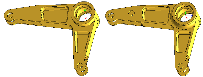
This example demonstrates how to perform the comparison:
sHoopsExchangeLoader.Import(A3DImport(filename1));
A3DAsmModelFile* modelFile1 = sHoopsExchangeLoader.m_psModelFile;

sHoopsExchangeLoader.Import(A3DImport(filename2));
A3DAsmModelFile* modelFile2 = sHoopsExchangeLoader.m_psModelFile;

A3DCompareOutputData pOutput = A3D_MAKE_DATA(A3DCompareOutputData);
A3DCompareFacesInBrepModels(modelFile1, modelFile2, 1, &pOutput);
The output structure contains information related to which faces are changed.
For example, the A3DCompareOutputData.m_pOldFaceMatch array corresponds to the array of faces, A3DCompareOutputData.m_pOldFace, found in the model.
m_pOldFaceMatch contains a A3D_TRUE value for each face that remains the same.
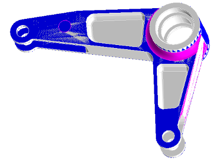
Perhaps most interesting is the m_pResultAsmModeFile field, which can be exported to PRC.
The PRC will contain all the faces color-coded according to their status in m_pOldFaceMatch.
The result is something like this:
Model Sewing
In some legacy file translators - especially those doing STEP or IGES translation - the relationship between adjacent faces in a solid body may be broken. HOOPS Exchange can repair this data through model sewing, which is a form of healing. Sewing reconnects adjacent faces in a solid.
Sewing can be done at the model file level or at the B-rep level using:
Below code is an example of using sew at model file level:
void UsingSew(A3DRiBrepModel* model1, A3DRiBrepModel* model2)
{
   A3DRiBrepModel* pInModels[] = { model1, model2 };

   A3DRiBrepModel** outModels = NULL;
   A3DUns32 numOutModels = 0;

   A3DSewOptionsData sOptions = A3D_MAKE_DATA(A3DSewOptionsData);

   A3DSewBrep(
      &pInModels,   // The input models array
      2,            // The number of input models
      sOptions,     // The settings
      1.0,          // The maximum tolerance in file unit
      &outModels,   // The output array of sewed models
      &numOutModels // The number of output models
   );
}
Currently one option is available: A3DSewOptionsData.m_bComputePreferredOpenShellOrientation.
By definition, open shells do not have a proper inward/outward orientation. With this option enabled (A3D_TRUE) an orientation is inferred even if is it an open shell and the sewing uses this information. The default value is A3D_FALSE.
In general, 0.1mm is the recommended tolerance. Internally, our algorithm will try to use a smaller tolerance (1 micron). This tolerance will be increased progressively until there are no more faces to sew, without exceeding the tolerance of 0.1mm. In other words, if two faces have a gap greater than 0.1mm, they will not be sewed.
T-Junctions Detection and Removal
A T-junction occurs when two adjacent triangles subdivide the edge of a third triangle, hence forming T-shaped edge junction. T-junctions can cause issues in rendering, such as visible seams and cracks, or problems in simulations and mesh deformations due to the lack of proper vertex connections, leading to geometric inconsistencies.
As of version 2024.7.0, HOOPS Exchange now provides a way to detect and remove T-junction from geometry.

T-junctions detection and removal. Each pair of vertices in a green zone represent the same vertex (indices and coordinates).
When a T-junction is detected in a geometry, HOOPS Exchange repairs it by projecting the additional vertex onto the overlapping edge, ensuring proper vertex connectivity.
Repairing T-junctions is available through the A3DMeshRepair() function:
A3DMeshRepairParametersData sRepairData = A3D_MAKE_DATA(A3DMeshRepairParametersData);
sRepairData.m_bRemoveTJunctions = A3D_TRUE;

A3DMeshRepair(psModelFile, &sRepairData);
Computing Sections
HOOPS Exchange is capable of performing model sectioning. You provide a model and define a plane. Then, HOOPS Exchange will create an infinitely thin slice of the model which intersects the plane. The output is an exact geometric B-rep slice, not just a tessellated polyline. The slice is provided as a set of B-rep representation items.
// initialize the section plane
A3DPlanarSectionData sectionPlane = A3D_MAKE_DATA(A3DPlanarSectionData);
// plane origin point
A3DVector3dData origin = A3D_MAKE_DATA(A3DVector3dData);
origin.m_dX = 0;
origin.m_dY = 0;
origin.m_dZ = 0;
sectionPlane.m_sOrigin = origin;
// plane direction
A3DVector3dData direction = A3D_MAKE_DATA(A3DVector3dData);
direction.m_dX = 0;
direction.m_dY = 1;
direction.m_dZ = 0;
sectionPlane.m_sDirection = direction;
A3DUns32 numSections;
A3DRiSet** sectionElements;
A3DComputePlanarSectionOnModelFile(sHoopsExchangeLoader.m_psModelFile,
§ionPlane,
&numSections,
§ionElements);
// 'sectionElements' contains the B-Rep for the sections
HOOPS Exchange also offers the ability to compute a section for individual B-rep models within an assembly.
The process is similar to the above example, except you would use the function A3DComputePlanarSectionOnRepresentationItem.
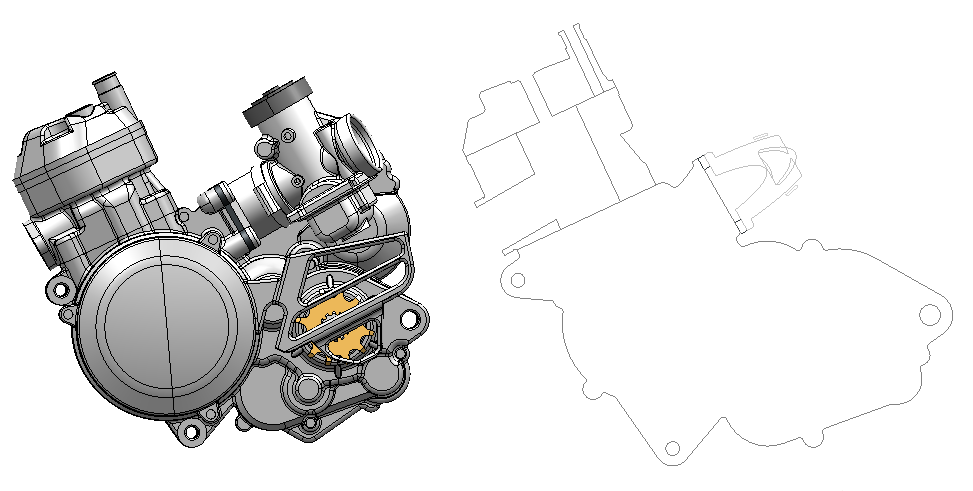
An example result of the section functions is shown below.
The original model is on the left.
The computed section is on the right.
Model to Point Cloud Comparison
Many manufacturers of high-precision machined parts have a need to quickly verify whether a finished part meets required tolerances. HOOPS Exchange can perform such an operation by comparing a CAD model with a point cloud dataset of the finished part. The comparison can be performed against the model’s exact mathematical definition or its tessellated representation.
The function that does this work is A3DProjectPointCloud.
This function accepts the model definition and a point cloud supplied from a laser scanner or other tool.
It returns a projected point cloud , which represents the difference between the real-world part and its mathematical definition.
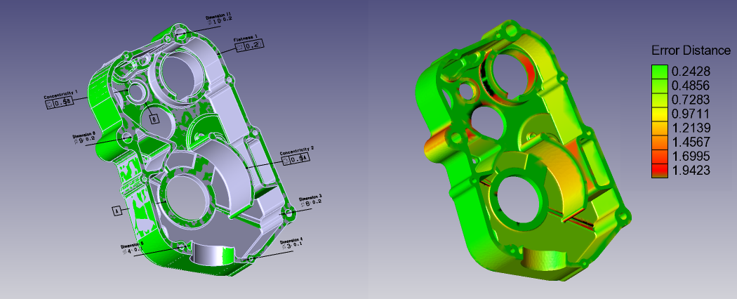
You can use the point cloud to visually inspect any tolerance deficiencies in the manufactured part. For example, in the image below, a CAD model is shown next to a point cloud of a scanned real-world object.
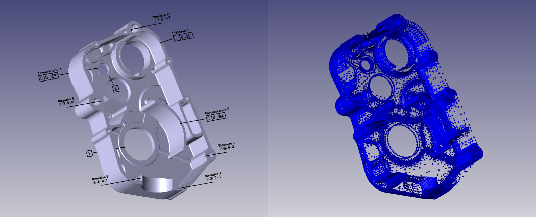
Using the projected point cloud returned from A3DProjectPointCloud, a the real-world surface can be overlaid (below, left) on the model.
Or, a heat map (below, right) could be applied to the model to show defects in tolerance:
A3DProjectPointCloud is recommended over inspecting each point individually because our algorithm is able to inspect multiple points simultaneously using multi-threading, automatically determines which points should be compared against each face, and is able to batch comparison operations together to further boost performance.
Of additional interest is A3DProjectPointCloud2, a similar function which can use a A3DProjectPointCloudManager to optimize the computation time when projecting several consecutive point cloud lists onto the same model.
Shattered Loading
Shattered loading refers to loading all files in an assembly individually as modules, rather than as dependencies. This type of loading is beneficial when dealing with large models with many parts, such as those managed by a PLM system. If such a model was loaded conventionally, any small change to one of its parts would require a complete reload of the entire assembly, which could take a significant amount of time. Shattered loading solves this problem by loading each part as a module that can be updated without regenerating the entire assembly. This approach can also offer considerable performance benefits by enabling you to load elements of the assembly concurrently.
In order to make use of shattered loading, you must load an assembly that was saved as a shattered assembly. This means you must load each CAD file in the assembly with the “shattered” option (using the option LoadStructureOnly = true). Once done, the file can be exported to PRC - no specific option needs to be used. If we do that for each CAD file in an assembly, we’ll obtain a list of PRC files. This list of PRC files can be used to reload the full model using A3DAsmModelFileLoadFromPRCFiles.
When doing your import, set your import structure’s m_bLoadNoDependencies field to 0 to cause no dependencies to be loaded:
A3DImport sImport(ppAssembly); sImport.m_sLoadData.m_sIncremental.m_bLoadNoDependencies = true;
Repeat this process for each file. When finished, the full model will be loaded into memory from these multiple independent parts.
Collision Detection
A static clash/collision detection function is available to determine if there is interference between parts within an assembly. As well as detecting interference, the function checks the clearance of parts for a given safety distance and whether the part is completely enclosed within the part that it’s being compared to.
Currently, collision detection only works on tessellated data.
The function A3DCollisionCompute takes either one or two groups of Representation Items as input.
If only one group is provided, then A3DCollisionCompute will determine if any of the parts within the group are clashing.
To use just one group, call A3DCollisionCompute with the second argument set to 0:
A3DCollisionCompute(
   &sGroup1, 0,
   &sCollisionParameter,
   &uCollisionResultsSize,
   &apCollisionResults
);
If two groups are provided, then A3DCollisionCompute will determine if any of the parts from the first group are clashing with any parts from the second group and vice versa.
It will not test for collision between parts within their own group.
The following are the potential values of the A3DCollisionResultData.m_eStatus member that is populated
by A3DCollisionCompute:
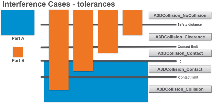
- NoCollision: No collision or contact.
- Clearance: These two representation items are closer than the safety distance.
- Contact: There is contact between the two representation items.
- Collision: There is a collision between the two representation items.
- FirstInside: The first representation item is completely contained inside of the second representation item.
- SecondInside: The second representation item is completely contained inside of the first representation item.
- Unknown: Result not computed or available.
The following picture represents the first four of these scenarios:
In order to use A3DCollisionCompute, it’s necessary to initialize and populate some of its parameters in advance.
The first two parameters contain the group(s) of parts to analyze; these parameters are of type A3DCollisionGroupData, which contain an array of Representation Items.
For specific details on how to retrieve the IDs of parts to compare, please see the collision example in the package.
The third parameter is of type A3DCollisionParameterData, which contains 1) the safety distance between parts for determining whether or not they have sufficient clearance, 2) the tessellation tolerance for the precision of the computation, and 3) the contact limit which specifies the threshold above and below an edge at which parts are considered to be merely in contact and not colliding (please see the ref A3DCollisionParameterData “API Reference” for further details on these settings):
A3DCollisionParameterData sCollisionParameter = A3D_MAKE_DATA(A3DCollisionParameterData);
sCollisionParameter.m_dContactLimit = 0.1;
sCollisionParameter.m_dSafetyDistance = 1.;
sCollisionParameter.m_dTesselationTolerance = 0.01;
Once our input parameters are initialized, we’re ready to call A3DCollisionCompute.
We’ll first initialize our empty output parameters, and then call the function:
A3DUns32 uCollisionResultsSize = 0;
A3DCollisionResultData * apCollisionResults = nullptr;
A3DStatus iRet = A3DCollisionCompute( &sGroup1, &sGroup2,
&sCollisionParameter,
&uCollisionResultsSize, &apCollisionResults);
The apCollisionResults array will now be populated, and you can inspect its elements to see the results of the collision detection.
Rigid Links
Some geometric entities are linked together so that they remain rigidly connected. The first purpose of this link information is for some CAD tools to maintain the same displacement between attached components. Components which are rigidly connected will maintain their relative positions.
Getting the List of Components Locked to an Owner
POB1 is connected to PO (ROOT).
With this example, calling A3DAsmGetFixedComponents with PO (ROOT) as owner will get you an array containing POB1.
Getting the Sets of Fixed Components
Consider the following example:
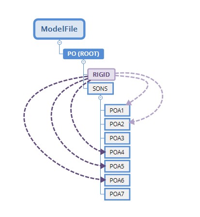
In this example we have two groups of rigidly linked components:
POA1 and POA2
POA4, POA5 and POA6
The two groups can be retrieved from a call to
A3DAsmGetFixedTogetherComponents. This function takes an owner node as parameter and returns a set of arrays. Each array is a group of rigidly linked components:
A3DUns32 uiNRGroups                = 0;
A3DUns32* uiNRComponents           = NULL;
A3DAsmProductOccurrence** ppGroups = NULL;

void ProcessPO(A3DAsmProductOccurrence* po);

A3DStatus iResult = A3DAsmGetFixedTogetherComponents(
   pOwnerNode,      // given pOwnerNode as the owner node
   &uiNRGroups,     // The number of groups
   &uiNRComponents, // The number of connected components in each group
   &ppGroups        // The array of connected components for each group.
);

if(iResult == A3D_SUCCESS)
{
   // Will call:
   // ProcessPO(POA1);
   // ProcessPO(POA2);
   // ProcessPO(0);
   // ProcessPO(POA4);
   // ProcessPO(POA5);
   // ProcessPO(POA6);

   for(A3DUns32 g = 0 ; g < uiNRGroups ; ++g)
   {
      for(A3DUns32 c = 0 ; c < uiNRComponents[g] ; ++c)
      {
         ProcessPO( ppGroups[g][c] );
      }
      ProcessPo(0);
   }

   // Free allocated memory
   A3DAsmGetFixedTogetherComponents(NULL, &uiNRGroups, &uiNRComponents, &ppGroups);
}
Getting the Flexible Components
By default, all members defined in a sub-assembly are considered as fix together and it is not possible to move one of them without moving the others. A Flexible node is a sub-assembly that allows new position for his sons defined by one of his father node.
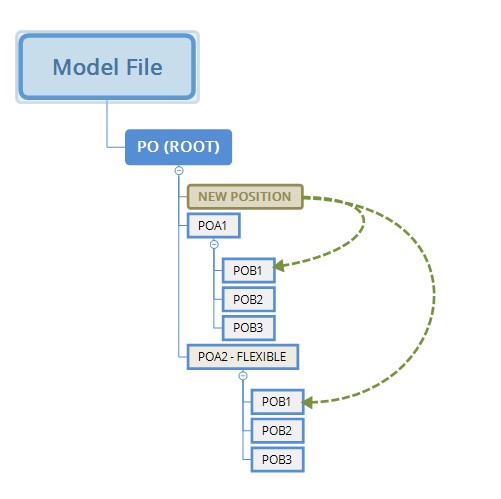
In the above image all members of POA1 will be moved together. Yet for POA2 only PO2/POB1 will be repositioned.
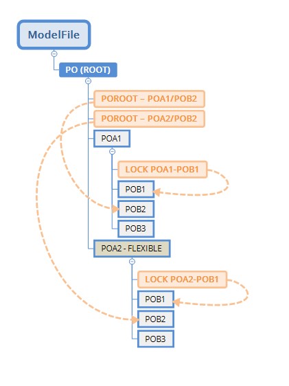
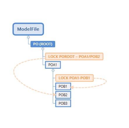
In this more complex example, the following occurs:
- POA1 not flexible (rigid). The sub assembly is considered as one body, so all positions are fixed by the lock POROOT on POA2/POB1POA1/POB2
- POA2 flexible
- POA2 / POB1 is fixed by the lock POA2 on POB1
- POA2/POB2 is fixed, by the lock POROOT on POA2/POB2
- POA2/POB3 is movable
To query the list of flexible subnodes, use A3DAsmGetFlexibleComponents.
HOOPS Exchange supports reading rigid links between components for the following formats:
- CATIA
- NX
- SolidWorks
- Creo