
Reading Tessellation
Note
This document presents how to read tessellation from a representation items using the PRC structure.
For a simplified access to tessellation using A3DMeshData, see Getting Tessellation using A3DMeshData.
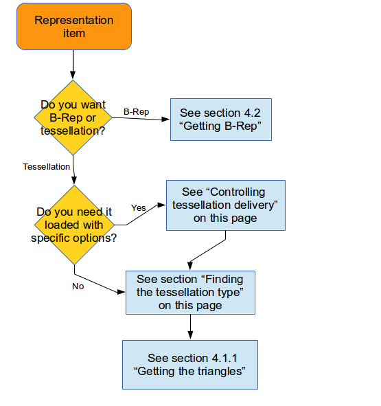
Tessellation entities represent polygon facets. HOOPS Exchange can use a variety of structures for tessellation, and they are all parsed in a slightly different way. Additionally, since representation items can also store B-rep, there is a specific flow to interpreting them. Assuming you have a reference to the representation item, the general operation is as follows:
Controlling Tessellation Delivery
HOOPS Exchange can give you the tessellation for any representation item at any time.
However, for many applications, getting the default tessellation is not sufficient because your application may have specific expectations for how it is formed.
For this reason, HOOPS Exchange gives you the ability to control how tessellation is delivered.
The A3DRWParamsTessellationData structure has various fields that affect the delivery:
- TessellationLevelOfDetail - A high-level setting comprised of other A3DRWParamsTessellationData preset values. Alternatively, you can specify your own set of values if you choose UserDefined.
- AccurateTessellation - By default, the tessellation is set for visualization, which is the right choice for a smaller footprint. Setting this value to A3D_TRUE will generate tessellation suited more for analysis. Can be used with all tessellation levels of detail.
- AccurateTessellationWithGrid - An accurate tessellation mode where point insertion is based on a grid layout.
- ChordHeightRatio - Specifies the ratio of the diagonal length of the bounding box to the chord height.
- AngleToleranceDeg - Specifies the angle between two continuous segments of an edge.
- MaxChordHeight (and UseHeightInsteadOfRatio) - Specifies the maximum distance between a surface and the generated tessellation. This is used (instead of ChordHeightRatio) by setting.
- UseHeightInsteadOfRatio - A very small value for MaxChordHeight can cause a very large amount of triangles to be generated.
- KeepUV - Keeps parametric points as texture points.
An example of using the A3DRWParamsTessellationData structure is shown below:
A3DRWParamsTessellationData tessellationParameters = A3D_MAKE_DATA(A3DRWParamsTessellationData);

// setting the tessellation detail to 'extra low'
tessellationParameters.m_eTessellationLevelOfDetail = kA3DTessLODExtraLow;

// the tessellation itself is retrieved by this call
A3DRiRepresentationItemComputeTessellation((A3DRiRepresentationItem *) pRepItem, &tessellationParameters);

// get the representation item associated with the tessellation you requested
A3DRiRepresentationItemData repItemData = A3D_MAKE_DATA(A3DRiRepresentationItemData);
A3DRiRepresentationItemGet(pRepItem, &repItemData);
The effect of some of the settings can be seen in this chart:
| Level of Detail | With AccurateTessellation | Without AccurrateTessellation |
|---|---|---|
| low | 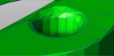 |
 |
| medium | 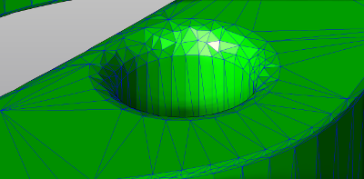 |
 |
| high | 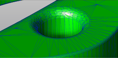 |
 |
More examples of the various quality settings can be found here.
Grid-Aligned Tessellation
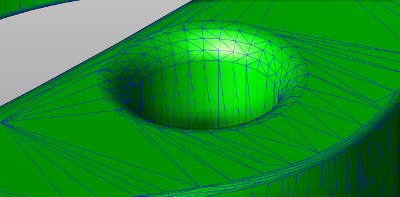
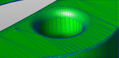
The grid-aligned tessellation allows accurate tessellation to obtain more regular triangles, where point insertion is based on a grid layout.
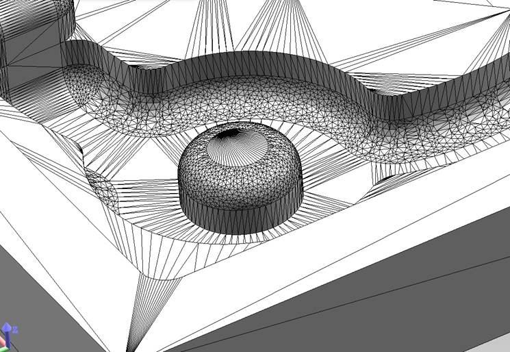
Standard accurate tessellation
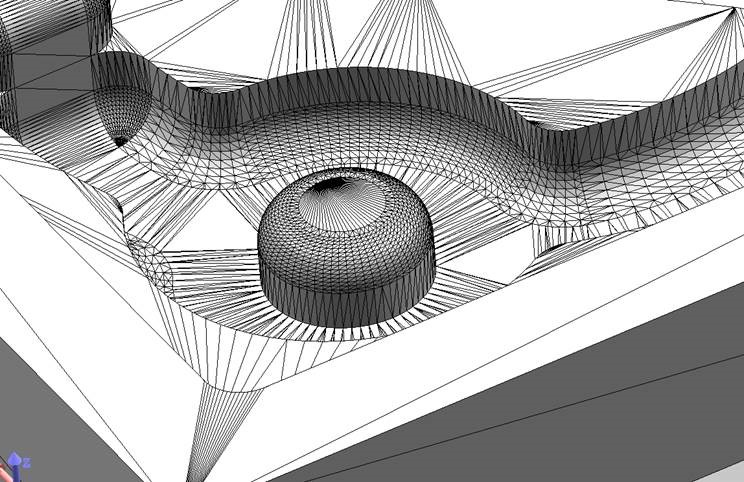
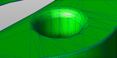
Accurate tessellation with grid-aligned point insertion
To enable this feature, set A3DRWParamsTessellationData.m_bAccurateTessellationWithGrid to A3D_TRUE.
If set, accurate tessellation using grid-based point placement will be used no matter what the value of A3DRWParamsTessellationData.m_bAccurateTessellation is.
Restricting Tessellation Grid Size
When performing grid-based tessellation, the maximum grid stitch length may be defined. This can lead to a more regular grid. This maximum value may be set using A3DRWParamsTessellationData.m_dAccurateTessellationWithGridMaximumStitchLength. This field is a double floating point value used as a reference for the grid. Setting the value to 0.0 will disable the constraint, which is the default behavior.
A very small value may lead to a huge number of points, thus a very long tessellation process.
Side Effects of Grid-Based Tessellation With Curved Surfaces
As of 2018 SP2, HOOPS Exchange provided a new parameter for accurate tessellation: A3DRWParamsTessellationData.m_bAccurateSurfaceCurvatures.
With this option the tessellation tends to create more adapted triangles along curvatures.
Now when using both this option and A3DRWParamsTessellationData.m_dAccurateTessellationWithGridMaximumStitchLength with a small value the generated triangles may not meet expectations.
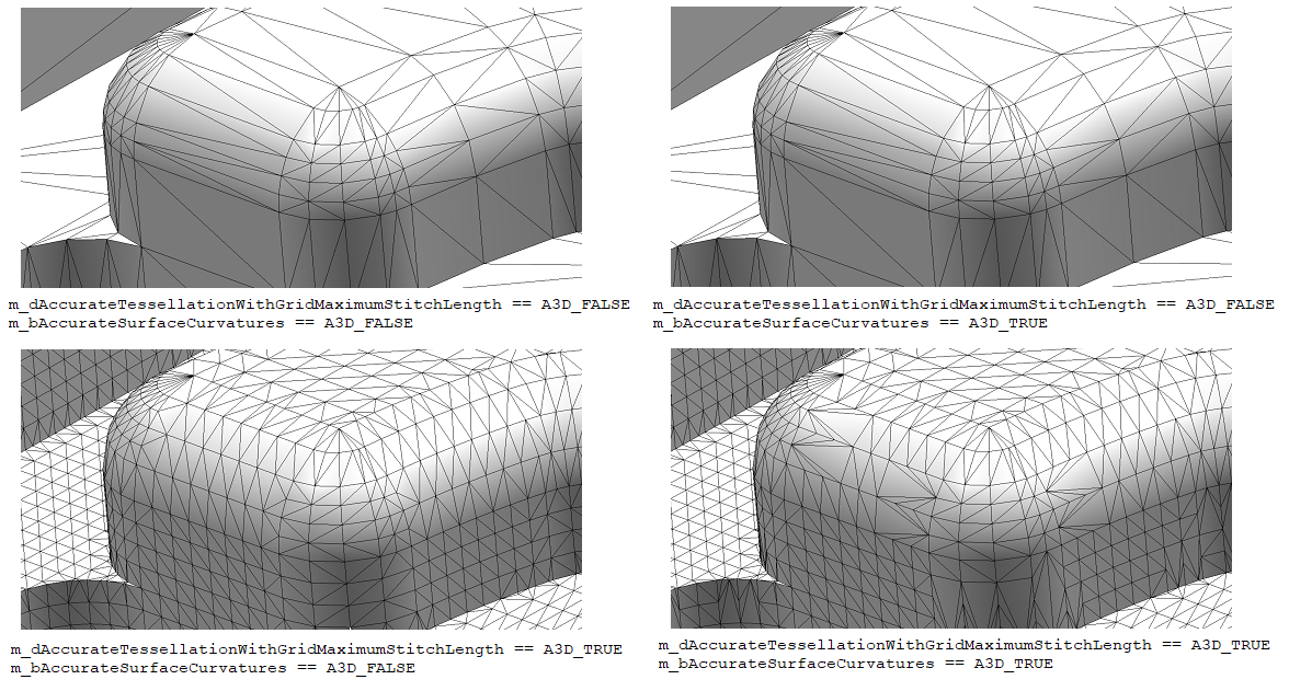
Comparing grid-based tessellation with or without constraints and surface curvature options
Finding the Tessellation Type
HOOPS Exchange can use a variety of different data structures to represent tessellation depending on how the triangles are arranged. Therefore, to get the actual geometry that makes up the tessellation, you first need to examine the tessellation type before getting a reference to the underlying data structure. Possible types include:
A3DBaseTessData: contains a point array m_pdCoords used to define triangles and linesA3DTess3DData: contains normals (m_pdNormals) and an index array (m_puiTriangulatedIndexes) which are used to display a shell or solidA3DTess3DWireData: used to display lines or curvesA3DFaceTess3DData: used to display groups of triangles, quads, strips, or defines solid facesA3DTessMarkup: defines markup visualization information [PMI]
Like B-rep, tessellation is always stored as part of a representation item. The tessellation types have the following UML relationships:
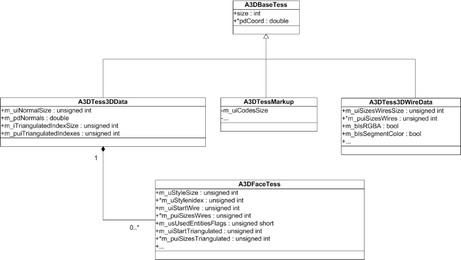
When you ask HOOPS Exchange to examine a representation item and return the tessellation type, it will return the type as some constant starting with kA3DTypeTess The A3DEntityGetType method gets this constant for any HOOPS Exchange object, including tessellation types. Therefore, you could do this to get the type:
A3DEEntityType eType;
A3DEntityGetType(repItemData.m_pTessBase, &eType);


// find out the object's type
switch (eType)
{
        case kA3DTypeTess3D:
        // handle tessellation with normals and index array
        A3DTess3DData sTess3DData = A3D_MAKE_DATA(A3DTess3DData);
        A3DTess3DGet(pTess3D, &sTess3DData);
        case kA3DTypeTess3DWire:
        // handle wire tessellation
        // ...
        case kA3DTypeTessMarkup:
        // handle triangle tessellation
        // ...

        // test for other types
}
Getting the Triangles
Retrieving tessellated triangles from a PRC representation item is a multi-step process, which requires examining the vertices of the tessellation and determining out how they’re connected to each other (e.g., triangles, tri-strips, or fans). Here are the steps:
Step 1: Get the tessellation vertices
Now that you know the tessellation type and have a reference to the data structure, you can get the vertices and faces that make up the geometry.
To get the raw points associated with the model, examine the representation item’s m_pTessBase.m_pdCoords field:
// get the tessellation base entity from the representation item
A3DTessBase* tessBase = riData.m_pTessBase;

// fill the tessellation data structure
A3DTessBaseData tessBaseData = A3D_MAKE_DATA(A3DTessBaseData);
A3DTessBaseGet(tessBase, &tessBaseData);

for (unsigned int n = 0; n < tessBaseData.m_uiCoordSize; n++)
{
     // get each coordinate
     tessBaseData.m_pdCoords[n];
}
Step 2: Accessing the index array
The code snippet in Step 1 gives you the model’s vertices but does not tell you how the faces are connected. Connectivity information is stored in an array within each tessellation structure. For example, in A3DTess3DData the m_puiTriangulatedIndexes array.
For this example, imagine our index array looks like this:
// pseudocode example
sTess3DData.m_puiTriangulatedIndexes = [ X X X 6 12 15 21 24 27 30 33 36
                                         39 45 48 51 54 60 81 45 84 96 99 87 90 93
                                         105 102 108 111 114 117 130 ]

// offset into m_puiTriangulatedIndexes where data begins
A3DTessFaceData::m_uiStartTriangulated = 3;
This array controls the relationship between points and faces. The meaning of each value will be explained in Step 4. But we need one more piece of information first.
Step 3: Find tessellation representation
CAD systems will often optimize lists of triangles by removing redundant vertices and forming triangle strips or fans.
HOOPS Exchange uses the same concepts to represent tessellation in PRC.
A3DTess3DData.m_psFaceTessData.m_usUsedEntitiesFlags is a bit field flag which indicates the types of tessellation present in the tessellation structure.
Possible tessellation types include triangles, triangle strips, and triangle fans.
You should check which types of tessellation are present because the result will affect the way the rest of the structure is interpreted.
A3DTess3DData sTess3DData = A3D_MAKE_DATA(A3DTess3DData);
A3DTess3DGet(pTess3D, &sTess3DData);

// iterate over the faces
A3DUns32 tessArraySize = sTess3DData.m_uiFaceTessSize;

for (int i = 0; i < tessArraySize; i++)
{
        A3DTessFaceData &sTessFaceData = sTess3DData.m_psFaceTessData[i];

        // get the specific tessellation type
        if (sTessFaceData.m_usUsedEntitiesFlags & kA3DTessFaceDataTriangleStripe)
                // triangle strips are used
                ;

        if (sTessFaceData.m_usUsedEntitiesFlags & kA3DTessFaceDataTriangleFan)
                // triangle fans are used
                ;
Step 4: Interpret index array
Finally, we have enough information to get the complete tessellation.
The A3DTess3DData.m_psFaceTessData.m_puiSizesTriangulated field is the array which brings together all the information we’ve collected.
Let’s imagine that the array has this value:
// pseudocode example
m_puiSizesTriangulated = [ 3 2 8 6 1 7 ]
This array represents the tessellation types and the number of vertices that correspond to that type. Tessellation metadata is always packed in the following way:
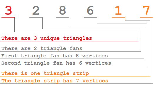
We’ll use this information to interpret the array in the following code snippet. This is one such arrangement the array could represent:
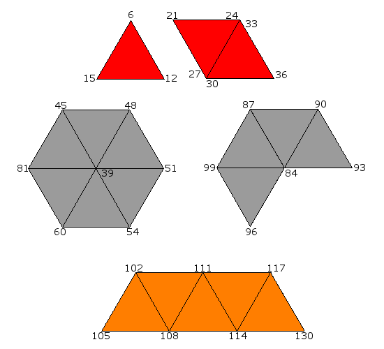
In this image, the red color indicates individual triangles, the orange indicates triangle strips, and the gray indicates triangle fans.
The numbers on the vertices correspond to the array A3DTess3DData.m_puiTriangulatedIndexes which in turn indexes the A3DTessBaseData.m_pdCoords array.
Revisiting the m_puiTriangulatedIndexes array:
// pseudocode example

// offset into m_puiTriangulatedIndexes where data begins
A3DTessFaceData::m_uiStartTriangulated = 3;

// the index array
sTess3DData.m_puiTriangulatedIndexes = [ X X X
    6 12 15                             // First triangle
    21 24 27                            // Second triangle
    30 33 36                            // Third triangle
    39 45 48 51 54 60 81 45             // First fan
    84 96 99 87 90 93                   // Second fan
    105 102 108 111 114 117 130         // Strip
]
From m_puiSizesTriangulated with value [3 2 8 6 1 7], we know we have 3 triangles - starting from offset 2 in the array - and they are made from the indices [6 12 15], [21 24 27], and [30 33 36]. Each of these indices point to a set of 3 entries in m_pdCoords Using this information, we know the first triangle would have these points:
- x = m_pdCoords[6], y = m_pdCoords[7], z = m_pdCoords[8]
- x = m_pdCoords[12], y = m_pdCoords[13], z = m_pdCoords[14]
- x = m_pdCoords[15], y = m_pdCoords[16], z = m_pdCoords[17]
Next, m_puiSizesTriangulated indicates we have 2 triangle fans. It also tells us the first fan has 8 indices - [39 45 48 51 54 60 81 45], and the second fan has 6 - [84 96 99 87 90 93]. Finally, we read the triangle strips. We have one strip: [105 102 108 111 114 117 130].
Summary
A3DTessBaseData.m_pdCoordsis an array of all coordinates in the tessellation.A3DTess3DData.m_puiTriangulatedIndexesis the actual topology where each value is an index to a set of coordinates.A3DTessFaceData.m_uiStartTriangulatedindicates the index of the first vertex in m_puiTriangulatedIndexes.A3DTessFaceData.m_usUsedEntitiesFlagsflags the list of existing triangle types in the topology: unique, fans, strips.A3DTessFaceData.m_puiSizesTriangulatedgroups indices in m_puiTriangulatedIndexes according to m_usUsedEntitiesFlags.
A3DTess3DData.m_psFaceTessData.m_pucRGBAVertices has the tessellation color data.
At this point, you know the type of tessellation and can process it accordingly. All that is left is to represent the relevant data from the 3D tessellation data element in your export structure.
For an example on creating tessellation entities, see Tessellation Example.