
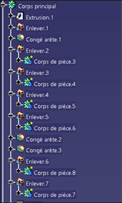
Feature Trees
The Feature Tree represents all the steps that have been taken in a CAD design system to create the final Part. For instance:
- Selecting a sketch and defining an extrusion.
- Selecting an edge and creating a fillet.
- Creating a hole.
A tree structure is usually an expressive way to describe features. The hierarchical structure allows a efficient representation of feature dependencies.
- An extrusion built on top of a sketch .
- A pattern based on a hole .
- A hole is defined on top of a hole thread .
With CATIA V5, Creo, NX and SolidWorks, HOOPS Exchange can be used to read the feature tree. It can then be traversed to retrieve all the parameters that have been used to define:
- Holes
- Patterns
- Extrusion
- Revolutions
- Fillets & chamfers
This information is particularly useful for optimizing downstream processes, including analysis, manufacturing, and metrology.
Reading the Feature Tree
To enable the features in your model, set A3DRWParamsGeneralData.m_bReadFeature to A3D_TRUE prior to importing your model:
A3DAsmModelFile* pModelFile = 0;

A3DRWParamsLoadData sReadParam = A3D_MAKE_DATA(A3DRWParamsLoadData);

sReadParam.m_sGeneral.m_bReadFeature = true;

// ... set other A3DRWParamsLoadData fields as necessary

A3DAsmModelFileLoadFromFile("path/to/file", &sReadParam, &pModelFile);
A Feature Tree is stored in the A3DFRMTreeData data structure:
typedef struct
{
   A3DUns16                    m_usStructSize;
   A3DUns32                    m_uiParametersSize;
   A3DFRMParameter**           m_ppsParameters;
   A3DUns32                    m_uiIntermediateGeometriesSize;
   A3DRiRepresentationItem**   m_ppIntermediateGeometries;
   A3DUns32                    m_uiInternalGeometriesSize;
   A3DRiRepresentationItem**   m_ppInternalGeometries;
} A3DFRMTreeData;
This structure can be obtained from any instance of A3DAsmProductOccurrenceData containing feature trees:
A3DVoid ReadFeatureTrees(const A3DAsmProductOccurrenceData* pPO)
{
   for(A3DUns32 fti = 0 ; fti < pPO->m_uiFeatureBasedEntitiesSize ; ++fti)
   {
      A3DFRMTreeData sData = A3D_MAKE_DATA(A3DFRMTreeData);
      A3DFRMTreeGet(pPO->m_ppFeatureBasedEntities[fti], &sData);

      // sData ready
   }
}
Data Structures in PRC
Geometry: 1) Final geometry, 2) Intermediate geometry, and 3) Internal geometry, which are defined as follows:
- Final geometry represents what is displayed in the 3D scene when opening the CAD file.
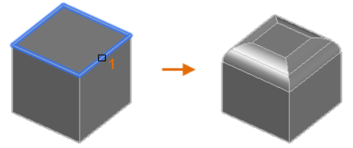
- Intermediate geometry represents entities that exist at some point during the solid construction. For instance, the blue loop in the picture below may exist only at the intermediate stage, before the chamfer (right picture) gets created. Consequently, it would be stored in the intermediate array of representation items.
- Internal geometry represents something created in the context of a given feature. An axis could, for instance, be created while defining an extrusion. In this case, it will be stored in the Internal representation item array.
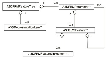
In addition to the arrays mentioned above, there’s another array in the A3DFRMTreeData data structure called m_ppsParameters, which contains A3DFRMParameter elements and is used to store the actual feature tree and feature information.
To describe the feature tree, we use a recursive Feature–Parameter structure.
An A3DFRMParameter contains an array of A3DFRMFeature elements, and A3DFRMFeature contains an array of A3DFRMParameter elements.
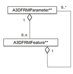
To avoid confusion with the feature tree, let’s call A3DFRMFeature a “feature object”.
Feature objects are used to store feature data – a fillet radius for instance.
A feature object can be a simple node or a container for a tree.
If it’s a leaf, it will describe data with an enum, integer, or string.
A Parameter is a node that has a type and is used to group and structure the feature objects it contains. A Parameter can have the following types: Container, Feature Definition, Type, Specification, or Data.
Let’s take a sample feature that can be defined using three points in CATIA, NX, or Creo. In this case, we’ll use a plane:
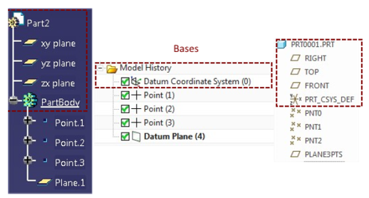
Now let’s look at how this plane would be stored in our parameter and feature objects.
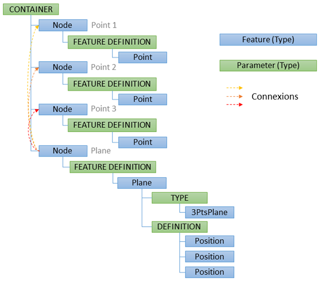
The plane is grouped in a parameter object with a feature definition type (in green just above the blue Plane node). The Feature Definition parameter object is itself contained in a feature object of type Node. Lastly, all of the elements are contained in a Parameter object of type Container.
Features of type Container and Node are the most frequently encountered types in the CAD feature tree.
Feature objects can also reference other features or geometrical entities using the A3DFRMLinkedItem data structure.
The plane example above, for instance, references three feature points.
Feature Information
HOOPS Exchange reads all the specific parameters that have been used to define a hole, pattern, extrusion, revolution, or fillet in V5, NX, and Creo.
The Parameters - Feature object is a generic data structure. In practice most features in the feature tree can be described with similar parameter and feature objects.
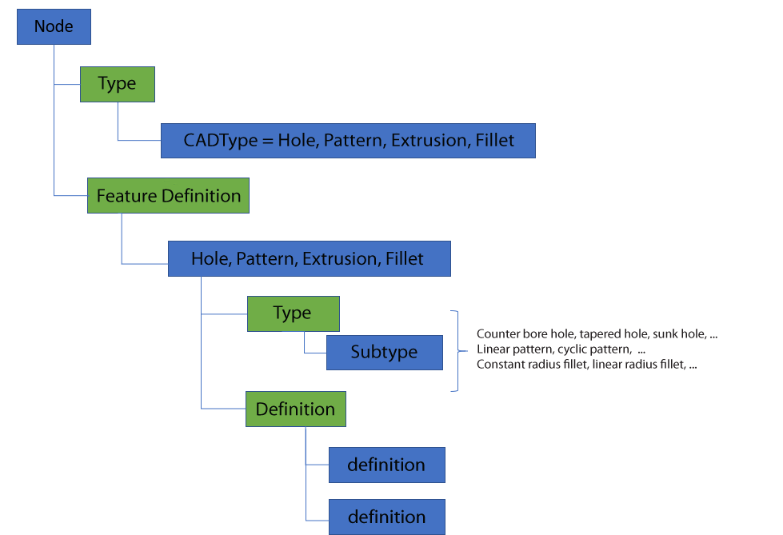
A feature object of type Node will contain two parameters, one of type Type and another of Feature Definition type. The Type parameter will provide general information on the feature – i.e., whether it’s a hole, an extrusion, a fillet, etc. The Feature Definition parameter will provide detailed information about the hole, fillet, or extrusion.
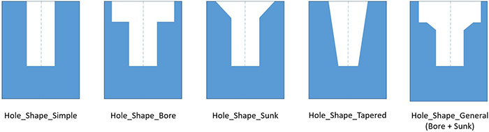
Hole Information
Every hole contains basic information such as depth and diameter:
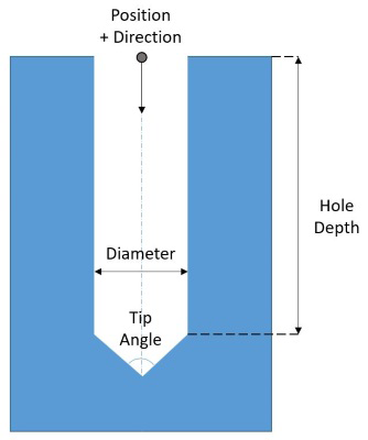
More complex hole types contain extra information. For instance, an additional angle is used to describe a tapered hole, whereas a sunk hole has an additional angle, depth, and diameter:
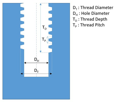
Thread information can also be included in a hole feature:
In the Parameter – Feature objects, all information is described in a feature of type Node.
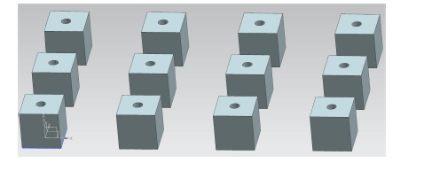
Pattern Information
Pattern information includes:
- Pattern type (Linear, Matrix, Cyclic, Polygonal)
- The Master entity
- Information to retrieve the position of slave entities
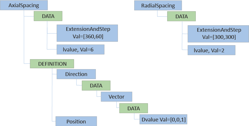
The Pattern feature object is stored inside a Feature Definition container:
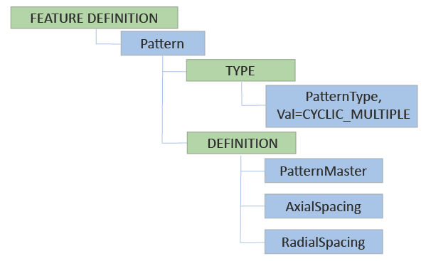
Spacing information is described in feature objects of type ref A3DEFRMDefinitionPatternType:
Extracting Sketches
HOOPS provides you with a function for extracting the sketches used in a feature assembly.
They are generated on-demand in a list of A3DRiRepresentationItem instances.
void ExtractSketches(const A3DFRMFeature* feature)
{
   A3DFRMGeomEntitiesData sketches = A3D_MAKE_DATA(A3DFRMGeomEntitiesData);

   A3DFRMGeomEntitiesExtract(feature, &sketches);
}
A3DFRMGeomEntitiesData is used to loop through the generated entities.
It is defined as:
typedef struct
{
   A3DUns16                  m_usStructSize;
   A3DUns32                  m_uiGeomEntitiesSize;
   A3DRiRepresentationItem** m_ppGeomEntities;
} A3DFRMGeomEntitiesData;
The content of m_ppGeomEntities is allocated at each call of A3DFRMGeomEntitiesExtract(), even if the function is called more than once on the same instance feature entity. To release the associated memory, call the function with no feature entity:
A3DFRMGeomEntitiesExtract(0, &sketches);
See Also
- The
A3DFRMGeomEntitiesDatastructure. - The
A3DFRMGeomEntitiesExtractfunction.
Feature Tree Traversal
If you’re just interested in a specific feature type, then use the A3DFRMGetSpecificNodes function, which takes an A3DEFRMEnumValue_CadType as a parameter, allowing you to search for planes, curves, shells, etc.
This example searches for all hole features in the feature tree:
A3DFRMTree* pTree;
...
A3DUns32 iSize;
A3DFRMFeature** ppFeatureNodes = NULL;
A3DFRMGetSpecificNodes(pTree, kA3DFRMEnumValue_CadType_Hole, &iSize, pppFeatureNodes);
For a demonstration of how to traverse and capture CAD feature information, please see the DumpFeatureTree example provided within the package.
Units in Feature Trees
Within a feature tree, unit information is expressed using an instance of A3DFRMFeatureData with the following attributes:
A3DFRMFeatureData::m_eDataTypeis set tokA3DFRMDataDouble.A3DFRMFeatureData::m_sType::m_eFamilyis set tokA3DFamily_DoubleData.A3DFRMFeatureData::m_sType::m_uiTypeis set tokA3DFRMDoubleUnit.
The attached A3DFRMDoubleData structure then defines at least one unit information.
Unit information is described in the context of the parent feature of the A3DFRMFeatureData instance.
Each successive unit in the underlying A3DFRMDoubleData object is used to describe the unit of a sibling feature in order.
The following example shows a configuration example of unit information provided in a “Sunk Definition” type hole:
// kA3DFRMDefinitionHoldeType_SunkDefinition:

.[0] = A3DFRMFeatureData { // Diameter
     .m_sType.m_eFamily = kA3DFamily_DoubleData
     .m_sType.m_uiType  = kA3DFRMDoubleUnit
},
.[1] = A3DFRMFeatureData { // Angle
     .m_sType.m_eFamily = kA3DFamily_DoubleData
     .m_sType.m_uiType  = kA3DFRMDoubleAngle
},
.[2] = A3DFRMFeatureData { // Units
     .m_sType.m_eFamily = kA3DFamily_DoubleData
     .m_sType.m_uiType  = kA3DFRMDoubleUnit
}
In this case, the attached A3DFRMDoubleData contains unit information twice, once for the diameter and once for the angle.
The unit values are interpreted as factors of millimeters, as described in Interpreting Units.