
Entities
In HOOPS Exchange, an entity can refer to any of the components that make up the model, such as product occurrences, part definitions, prototypes, externals, etc.
Product Occurrences
Product occurrences are the building blocks of the PRC assembly tree.
The product occurrence node, A3DAsmProductOccurrence, is meant to encapsulate a single part, an assembly of parts, or both.
The nodes themselves may also contain references to other product occurrences, entity references, annotations, filters, and other entities.
Product occurrence nodes are often nested, therefore, during traversal, a recursive algorithm is recommended.
If you’re doing a direct integration, you will need to parse the PRC structure after loading the model.
The first thing to do is to initialize HOOPS Exchange and get a reference to the model file data structure.
Using that structure (of type A3DAsmModelFileData), you can get access to the assembly tree.
The model file data structure (modelFiledata in the code snippet below) always has a reference to at least one product occurrence. In complex models, the model file may contain references to a list of product occurrences - this is called an assembly .
// number of product occurrences
modelFileData.m_uiPOccurrencesSize;

// list of product occurrences
modelFileData.m_ppPOccurrences;
After you get a reference to the product occurrence, parsing it is relatively simple because many of the fields are themselves product occurrences. You can use a recursive function such as this to get the product occurrences and their children:
// Traverse PO Recursively
A3DStatus traversePO(const A3DAsmProductOccurrence* pPO)
{
        A3DStatus iRet = A3D_SUCCESS;

        A3DAsmProductOccurrenceData sPOData = A3D_MAKE_DATA(A3DAsmProductOccurrenceData);
        A3DAsmProductOccurrenceGet(pPO, &sPOData);

        if (sPOData.m_pPart)
        {
                CHECK_RET(traversePart(sPOData.m_pPart));
        }

        if (sPOData.m_pPrototype)
        {
                CHECK_RET(traversePO(sPOData.m_pPrototype));
        }
        else
        {
                for (int i = 0; i < sPOData.m_uiPOccurrencesSize; i++)
                {
                        CHECK_RET(traversePO(sPOData.m_ppPOccurrences[i]));
                }
        }

        return iRet;
}
While traversing product occurrences, you’ll probably want to extract information contained within each product occurrence – e.g., parts, representation items, etc. To see a code sample for how to do this, please visit this page.
Note
The code example above simply demonstrates one way to acquire the information in a product occurrence. You can parse the assembly tree any way that makes sense in your application.
Part Definitions
Recall the significance of a part definition:
Part definitions contain metadata about the geometry such as as annotations, views, the bounding box, as well as a reference to the part’s geometric representation.
The class name is A3DAsmPartDefinition.
A product occurrence may only contain a single part definition.
Product occurrences are the only type of node that may contain a part definition, and each node may contain a single part. Regardless of whether a part definition is present, the node may reference other product occurrences, prototypes, or externals (which, in turn, may have their own part definitions), so you should always traverse those fields as well. Keep in mind that these fields are also product occurrences, so you can use the same recursive parsing function for each.
A part definition may be found in one of four places:
- in a product occurrence node m_pPart field
- in a prototype
- in an external
- in a child product occurrence node
Product occurrences may also contain graphical information associated with the model part in its part definition.
If such information is available, it will exist in the node’s A3DRootBaseWithGraphics() (see Colors and Materials).
Often, model creators will have a need to instance the same geometric data multiple times in the model file. Most file formats will define this data once and instance it wherever it is needed. The purpose is to avoid data duplication and have a single data point for ease of modification. In HOOPS Exchange, such a structure is called a prototype .
A prototype is a field of A3DAsmProductOccurrenceData.
It is a pointer to another product occurrence which contains geometry meant to be instanced in multiple places.
Since the prototype field A3DAsmProductOccurrenceData.m_pPrototype is a pointer to another product occurrence node (which could be a nested structure), your traversal algorithm should parse it no differently than any other product occurrence node.
If you find a product occurrence with neither children nor a part definition, the node likely has a reference to a prototype.
Although prototypes are a way to reference the geometry of another product occurrence, keep in mind that supporting information and attributes, such as color, line pattern, visibility, etc., can still be controlled on the prototype’s parent using A3DRootBaseWithGraphics.
As an example of an assembly tree using prototypes, consider a cube prototype that is instanced four times:
- The first instance is in the root product occurrence
- The second instance is in sub-assembly #1
- The third and fourth instances are in sub-assembly #2
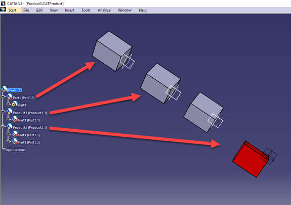
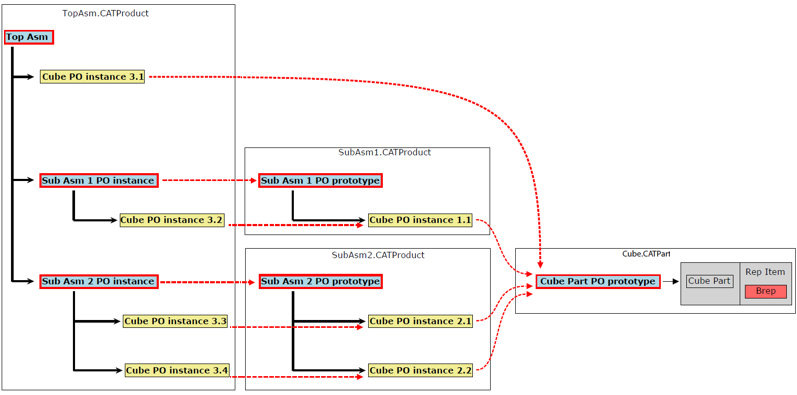
As you can see, the fourth cube (contained in sub-assembly #2) is red. Though it’s using the same prototype as all of the other cubes, its attributes have been changed in the product occurrence of this particular instance. Here’s the complete diagram of this assembly tree:
An external is a subassembly tree that has been created in a different CAD system than its parent file. Externals are represented by a product occurrence node. The concept is similar to a prototype, and thus they should be parsed the same way. The one important difference between the two is an external’s geometry and attributes cannot be modified due to limitations between their disparate authoring systems.
Each product occurrence structure has an entry for display parameters , A3DGraphSceneDisplayParametersData.
This structure contains the camera, lights, clipping planes, as well as information about various styling information.
Filters allow you to show or hide a set of geometry. The purpose is to bring attention to particular components, usually in order to simplify the model or express an idea. Filters are not found in all CAD files, and some file formats don’t support them at all. In HOOPS Exchange, filters are attached to product occurrence nodes.
A layer is simply a logical group of objects.
The objects are not required to be related in any way.
Layer indices are specified on the A3DGraphicsData structure.
An entity can only be linked to one layer.
Two types of filters exist - layer filters and entity filters.
A layer filter enables or disables an entity’s visibility based on its layer.
Entity filters maintain a list of entity references to geometry that will be filtered.
Both types of filters exist as fields on the A3DAsmProductOccurrenceData.m_pEntityFilter member.
The following code samples demonstrate how to get a list of filtered entities:
A3DAsmFilterData filterData = A3D_MAKE_DATA(A3DAsmFilterData);
A3DAsmFilterGet(poData.m_pEntityFilter, &filterData);

// get layer filters
A3DAsmLayerFilterItemData layerFilterItem = filterData.m_sLayerFilterItem;

for (int i = 0; i < layerFilterItem.m_uiSize; i++)
{
     // layer filter indices exist as unsigned integers
     // and are accessed through this field:
     layerFilterItem.m_puiLayerIndexes[i];
}

// get entity filters
A3DAsmEntityFilterItemData entityFilterItem = filterData.m_sEntityFilterItem;

for (int j = 0; j < entityFilterItem.m_uiSize; j++)
{
        // the entity filter exists as an array of A3DMiscEntityReference
        // and are accessed through this field:
        entityFilterItem.m_ppEntities[j];
}
Using the code above, you are able to get a list of entities that are affected by the filter and change your scene accordingly. Usually, this means turning off visibility for the filtered items, although you can apply any effect you require.
Configurations are an important option that can be utilized for certain file formats. A configuration is a sub-model within a larger model - sometimes these files are also referred to as “multi-model” or “multi-entry” files. Only CATIAV4, SolidWorks, and IDEAS files support configurations. Some files can contain multiple configurations. If you do not specify a configuration to load, the default configuration will be loaded, if possible.
If you do encounter a file with multiple configurations, use the A3DRWParamsMultiEntriesData structure to find which configurations or sub-models should be loaded.