UnstructGrid: Apply Part Settings to a Model

Various part settings can be applied to the different parts in the model to improve the visual representation of the data. Part settings are, for instance, visibility, highlighting, draw style, colors and result visibility.
Each part has its own settings.
This tutorial shows how to apply some part settings to parts in the model.
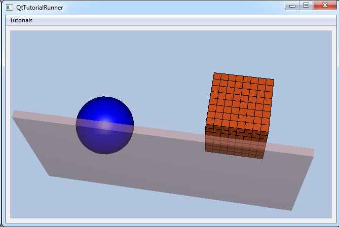
The demo file (contact.vtfx) contains a geometry with four parts. This tutorial shows how to set the following settings on these parts:
Part 1: Set invisible
Part 2: Set color to blue
Part 3: Set draw style surface mesh
Part 4: Set opacity
Load the file and setup the model specification to show the result. For a more thorough explanation on creating a data source from a file interface and setup the model specification, see the Load VTFx tutorial: UnstructGrid: Load Model from File and Set Up Model Specification
Note
This tutorial expect the application to have a correctly configured cee::vis::View
in place. See demo applications on how to set up a cee::vis::View in your application.
Load model
    cee::PtrRef<cee::ug::UnstructGridModel> ugModel = new cee::ug::UnstructGridModel();
    cee::PtrRef<cee::ug::DataSourceVTFx> source = new cee::ug::DataSourceVTFx(42);

    cee::Str vtfxFile = TutorialUtils::testDataDir() + "contact.vtfx";
    if (!source->open(vtfxFile, 0))
    {
        // VTFx file not found
        return;
    }

    ugModel->setDataSource(source.get());
Create the model and a VTFx file interface data source. Open the file and set the created data source in the model.
Set the first state as current in the model specification.
    std::vector<cee::ug::StateInfo> stateInfos = source->directory()->stateInfos();
    int stateId = stateInfos[0].id();
    ugModel->modelSpec().setStateId(stateId);
Part settings
Get the part ids for the four parts in this model. Part info is available in the data sources metadata directory. We know this model only has one geometry and four parts.
    std::vector<cee::ug::PartInfo> partInfos = source->directory()->partInfos(0);
    int firstPartId     = partInfos[0].id();
    int secondPartId    = partInfos[1].id();
    int thirdPartId     = partInfos[2].id();
    int fourthPartId    = partInfos[3].id();
Set the first part invisible
ugModel->partSettings(0, firstPartId)->setVisible(false);
Give the second part the color blue
ugModel->partSettings(0, secondPartId)->setColor(cee::Color3f(0.0, 0.0, 1.0));
Use surface mesh draw style at the third part
ugModel->partSettings(0, thirdPartId)->setDrawStyle(cee::ug::PartSettings::SURFACE_MESH);
Set the fourth part transparent
ugModel->partSettings(0, fourthPartId)->setOpacity(0.5f);
Set up the created model
The model is ready to use and can be added to the view. Exactly where the view exists
depends on the platform and solution. These examples uses Qt and the view is set up
in a cee::qt::ViewerWidget.
    cee::vis::View* gcView = getTutorialView();
    gcView->addModel(ugModel.get());
    ugModel->updateVisualization();
See the complete source code here:
