
HOOPS Demonstration Viewer
The HOOPS Demonstration Viewer (HDV) is a desktop application which demonstrates how HOOPS Visualize Desktop and HOOPS Exchange work together to provide a complete 3D CAD presentation. HDV is able to load any model file that is supported by HOOPS Exchange. You can then view and interact with model using HOOPS Visualize Desktop, our 3D visualization toolkit. Finally, you can use HDV to export the model to a different CAD industry format using HOOPS Exchange.
Licensing
The HOOPS Demonstration Viewer requires a valid license key to run. HDV is packaged with a trial license which allows customers to run the program for 30 days. When using a trial license, a message appears at startup, letting you know how many days you have left before the trial expires. The trial license can be converted to a permanent license by requesting a permanent license from Tech Soft 3D support.
Opening a File
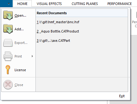
There are three ways to open a file:
1. By clicking on File/Open or pressing CTRL+O. Doing this will cause the following dialog to appear:
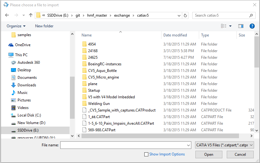
If you check the ‘Show Import Options’ check box, and then open a file, a dialog appears which allows you to specify import options for the file that was selected. See the next subsection for an explanation on import options. Clicking Open without checking ‘Show Import Options’ will import the selected file with the import options which were specified last (or the default ones, if they were never specified).
2. By dragging and dropping a file. When dragging and dropping a file, it is automatically opened using the import options the user last specified.
3. By choosing a file from the Recent Document list. When opening a file through the Recent Document list it will be imported using the import options the user last specified.
Import options
If you’ve selected “Show Import Options”, this dialog will appear:
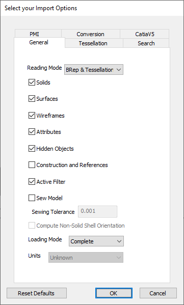
The first four tabs (General, Tessellation, Search, and PMI) will always be present, while the CatiaV5 tab will change (or disappear) based on the format of the selected file and the Conversion tab is available for non-HSF files.
General Tab
The “General” tab allows you to select which entities are imported: solids, surfaces, attributes, and construction entities. Depending on the type of file you’re opening, the following options will be available for Reading Mode:
- BRep and tessellation
- Tessellation Only
- Feature Trees - Choosing this reading mode will import B-rep, tessellation, and a feature tree. The feature tree will be visible in the Model Browser, and you’ll be able to interact with it to inspect the CAD features and collect their properties. Note that when importing feature trees, sewing and incremental loading is not supported. If the user selects the feature trees reading mode, the above-mentioned options will be changed to conform with the limitations of feature trees. Features are only available for CatiaV5, Unigraphics and ProE (Creo) files. The option to import feature trees will not be presented when importing files of other types.
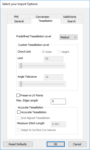
Tessellation Tab
The “Tessellation” tab allows the user to specify the level of tessellation from 5 preset levels, or to choose custom tessellation values. A higher tessellation level will result in a more detailed model at the cost of a slower import.
The grid-aligned tessellation option typically generates more regular triangles, where point insertion is based on a grid layout.
When performing grid-based tessellation, the maximum grid stitch length may be defined. This can lead to a more regular grid. A very small value may lead to a huge number of points, thus a very long tessellation process.
Other Tabs
- The “Search” tab specifies which folders Exchange should search when looking for file references.
- The “PMI” tab specifies whether PMI should be imported, its color, and a backup font to be used in case the original font cannot be found.
- The “Conversion” tab includes options for converting curves and surfaces to NURBS and also for surface splitting.
- The “CatiaV5” tab has V5 specific caching options.
These options, and the folder from which the user completes the import, will be saved to a preference file. They will be the same from one import to the next, and from one application run to the next.
All of these options, and the folder from which the user completes the import, will be saved to a preference file. They will be the same from one import to the next, and from one application run to the next.
Incremental loading
SolidWorks, NX (Unigraphics), Creo (Pro/E), JT, and CATIA V5 files may be loaded incrementally. This means that only the assembly tree is loaded into memory, but geometry is not. Specific parts may then be loaded using the Model Browser. Incremental loading saves time and memory because only the model skeleton is loaded. To enable incremental load, make sure the “Loading Mode” drop-down is set to “Incremental” in the load dialog.
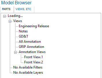
This is what the Model Browser will look like after an incremental load:
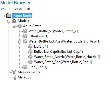
At this point, the user can select which of the product occurrences listed in the Model Browser to load. To do so, right-click the desired product occurrence and choose ‘Load’. Loaded product occurrences can also be unloaded, by following the same process and selecting ‘Unload’. Note that only the geometry on leaf product occurrences will be loaded.
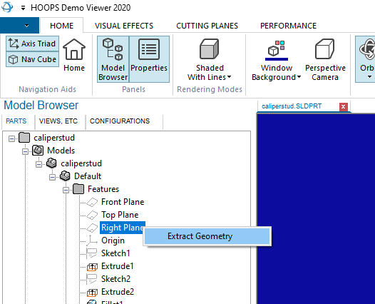
Feature trees
Extracting geometry from feature trees is available for models that support it, such as NX and Solidworks. To use this feature, load a model and right-click on the feature you want to extract. The “Extract Geometry” context menu will appear.
Loading multiple files into the same view
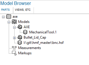
It is possible to load multiple models into the same view. This is accomplished using the “Add…” option from the main menu:
Any type of file can be added to CAD files. If the first file you loaded in a tab is a point cloud or an HSF file, then only other HSF and point cloud can be added to this tab.
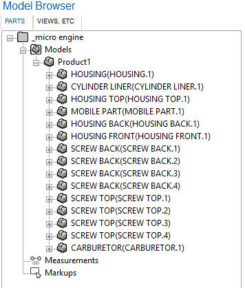
This is what the Model Browser looks like when you add two files together:
Files can be added at a very specific location in the parts hierarchy by right-clicking a product occurrence in the Model Browser and choosing ‘Add File…’
Multi Function Operator
The default operator for the HOOPS Demonstration Viewer allows the user to orbit, pan, zoom, zoom to extents, and select.
- Orbiting around the Camera target is activated with the left mouse button. Alternatively, you can orbit around the position under the mouse cursor by pressing the middle mouse button (as long as geometry is present underneath the mouse cursor).
- Panning is activated with the right mouse button.
- Zooming is activated through the mouse wheel.
- Zooming to extent is activated by a double left click on a portion of the main window not occupied by the model.
- Selection happens when the left mouse button goes up, if the location at which it goes up matches the location at which it went down.
- Hold shift to get dynamic highlighting
- Press ‘H’ to hide
- CTRL-A selects everything
After switching operators, the user can go back to this operator by clicking on Orbit, on the HOME tab.
The selection operator can select both faces and edges. Since selecting edges is always more difficult than selecting faces, the operator is designed to be biased towards selecting edges. Therefore, if the user performs a selection close enough to an edge, the edge will be selected even though the actual selection event happened on a face.
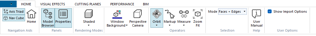
It is possible to restrict the selection operator to only selecting faces, or only selecting edges, by using the Selection Mode drop down menu at the far right of the HOME tab, pictured below:
NOTE: Except when measuring or inserting markup, it is always possible to select geometry as explained above.
Selection
Hierarchical selection
The default selection operator performs hierarchical selection. This means that if the user selects a component which is already selected, its owner will be selected instead. This creates a situation where selecting the same element over and over, moves the selection up through the hierarchy of components until the root model file is reached.
Not every component in the hierarchy is considered interesting, so some levels are skipped altogether. For example, the owner of a Topological Face is a Topological Shell. But the Shell is not very interesting and has no geometrical interpretation, so the Shell is skipped, and the Topological Body owning the Face is selected instead.
Hierarchical Selection uses the component structure to climb the hierarchy, and therefore it is not available on files which are not imported through Exchange, such as HSF, STL, OBJ and SKP files.
During the process of selection, physical properties are collected for the selected objects and are displayed on the Property Pane, and finally the selected geometry is highlighted. Note that importing a file with BRep is required for most of the properties to be available.
Multiple Selection
There are three ways of selecting multiple objects in the scene.
- By using the default operator, and selecting objects while holding down the CTRL button.
- By using the Area Select operator and dragging the mouse (an overlaid rectangle will be drawn to show the selection area).
- By selecting items in the Model Browser while holding down the CTRL button.
If an isolate operation is carried out while multiple objects are selected, all the selected objects will be shown while the rest of the model will be hidden. The camera will be smoothly reset to a bounding box which fits all the isolated objects.
If a hide operation is carried out while multiple objects are selected, all the selected objects will be hidden.
When selecting multiple objects, the property window will display properties for the last object you selected.
Some items (like views) which are present in the Model Browser cannot be selected, and therefore cannot be multi-selected either.
Highlighting
Highlighting happens when objects are selected through the default operator or the Area Select operator. The default highlight color is green. Geometry will be highlighted in orange if its color is close to green, so that the user always has a clear indication of what is highlighted.
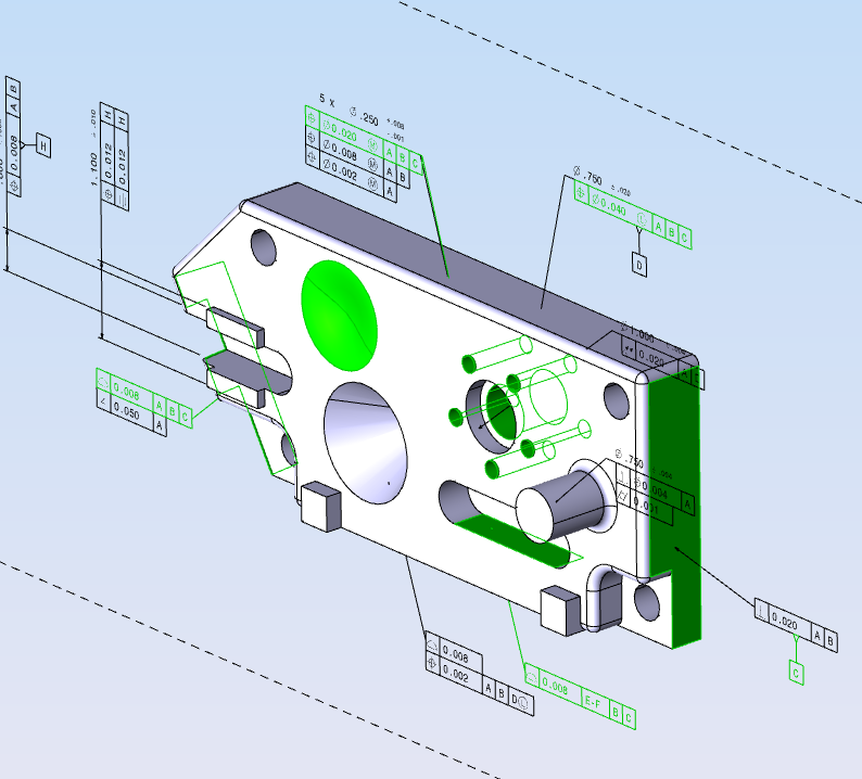
When a face is highlighted the edges related to that face are also automatically highlighted, and a depth range effect is applied to them, so that they are always visible through the model, as shown below:
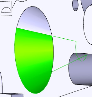
If a face has PMI attached to it, that piece of PMI will also be highlighted when the face is selected. Conversely, when highlighting a Datum (a particular type of PMI used to label a surface), its related face will be highlighted.
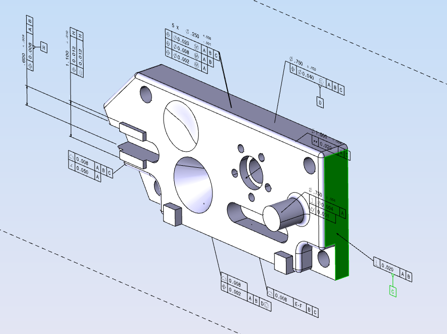
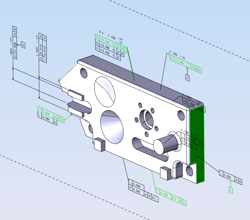
Clicking on the same Datum twice in a row, highlights all other pieces of PMI which also reference the same surface.
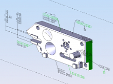
Clicking on the same Datum a third time in a row, highlights all other pieces of PMI which reference the same surface, and all the surfaces referenced by these other PMI. This is shows in the table below (click images to enlarge):
| Selecting in C | Selecting in C twice | Selecting in C thrice |
|---|---|---|
|
|
|
|
|
|
|

|
Dynamic highlighting
Dynamic highlighting is a method of highlighting where objects are highlighting simply by moving the mouse over the object without clicking. This mode is activated by holding down the shift button and moving the mouse around. No buttons clicks are necessary. During dynamic highlighting, edges cannot be selected.
Model Browser
The Model Browser is used to quickly select components and to inspect the component hierarchy. All components are available for inspection if you load a CAD model. Loading a non-CAD mdoel such as HSF, OBJ, or STL will yield a model browser which simply lists the model filename. In this case clicking on the filename node in the Model Browser will highlight the model on screen.
The model browser is constituted of three panes, with the third pane only shown under certain conditions.
Here is an explanation of the panes:
Model Browser pane
This is the first of the three panes. When the application starts it is shown on the left, on top of the other two panes. It contains the model component hierarchy. Clicking on an item will change its text to bold and will change the item background to blue, so users can tell which item is selected. If the selected item is a view, it is activated with a smooth camera change. If the item is a component, it is highlighted and its properties are shown on the property pane.
If you’re using a file type that supports CAD Features, then they will be available for inspection in the Model Browser, grouped under their respective Product Occurrences. Clicking on Features will highlight their related geometry in the scene, if any, and display their properties in the Property Pane. (See the Opening a file section for how to import files with CAD Features.)
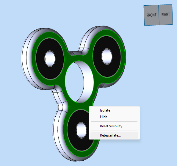
Right-clicking on certain components from the model browser will cause a context menu to appear. The context menu will give the user the option to either isolate or show a component, based on its current visibility state (hidden components can be shown, shown components can be isolated). The icon and text representing an item should be grayed out when the item is hidden.
Measurements and markups are also shown in the model browser. Individual measurements are displayed under the ‘Measurement’ tree node, and can be individually shown, hidden or deleted from the model browser. It is also possible to show or hide all measurements at the same time by using the main Measurement node in the Model Browser.
Markup is organized into layers and shown under the ‘Markups’ tree node. All markup inserts from the same camera belong to the same layer. It is possible to individually delete or activate markup layers from the Model Browser.
Views pane
The Views pane collects the views, filters and layers for a model. The views are further divided among annotation and non-annotation views. Clicking on a view will cause it to become active, smoothly changing the camera to fit the new view.
Filters and layers can be toggled by clicking on them. Note that activating a filter or a layer can, in turn activate other filters or layers. Filters and layers which are active are shown in bold. Not every model has views, filters or layers. In the case of a model lacking filters, for example, the string ‘No Available Filters’ will be shown in this pane.
Configuration pane
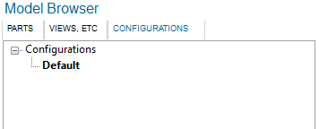
The Configuration Pane only appears if the model you have loaded contains more than one configuration. Like the name implies, it lists all the available configuration, with the active one displayed in bold. Double clicking on a configuration other than the one currently active causes that configuration to be loaded, which necessitates a full import.
Switching between loaded models will cause the different panes of the Model Browser to update as needed, with the Configuration Pane dynamically appearing and disappearing based on the tab which is currently active. If you reorganize the tabs so that you can see multiple models at once (for example by dragging a tab so that you have two side by side), the Model Browser will reflect the state of the active tab, of which there can only be one at any give time, and is the last tab you have interacted with.
Property Pane
The Property Pane is used to inspect the properties for the selected component. The type of properties which will be available depends on whether the model was loaded through Exchange, and whether an Exchange model was imported with B-rep. In order to obtain the largest set of properties for an Exchange model, it is necessary to import it with B-rep.
The Property Pane is divided into four sections, explained below:
- File properties
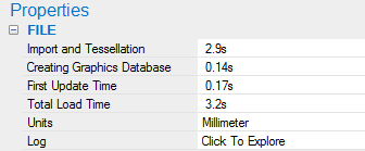
File properties include the total load time, broken down into multiple stages. The number and type of stages shown varies, based on whether the model was imported with Exchange or not. In the case of a file imported with Exchange, these stages are: import and tessellation, creating graphics database, first update time, and total load time. Import and Tessellation represents the time spent in the Exchange importer during which data is queried from Exchange. This time is mostly affected by changes in HOOPS Exchange. Creating Graphics Database represents the time spent in the Exchange importer building the scene graph. This time is mostly affected by optimizations in the Exchange importer. First Update Time represents the time spent by HOOPS Visualize Desktop to populate display lists, create a static model and issuing the first update. This time is mostly affected by optimization in the core code. Total Load Time is a sum of the previous timers. In the case of an HSF, STL or OBJ file, the first two timers are replaced by a single one, called Import Time. For Exchange files, this section also contains the units used in the file, and the import log. In order to see the import log, the user needs to click on the Log property cell. This will cause a separate window to pop up, displaying the import log HOOPS Visualize Desktop received from Exchange. At this point the user can switch between the Full or the Summary report, and save them to a text file if desired.
- General properties
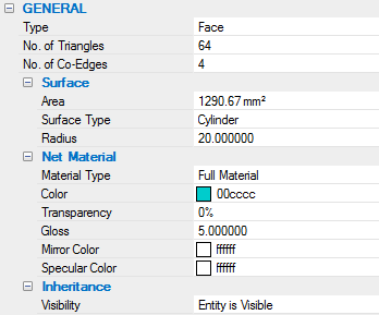
General Properties include geometric properties related to the face or edge which was selected. The property displayed change based on the type of component which is selected. The ‘Net Material’ subsection is populated from data obtained from the scene graph. All the other properties are populated by querying Exchange directly. Some properties, like ‘No. of Triangles’ and ‘No. of Co-Edges’, which can be time intensive to calculate, are cached into the scene graph, so that repeated requests for properties from the same components should be faster than the original query. In some cases, some properties are only available when the model is imported with BRep. If this is the case, the value of a property will clearly state so. When selecting an Edge, the properties shown include its length, and the properties of its Co-Edges, if available. Selecting a Face, shows its area, the number of triangles and the number of edges used to draw it. Additionally data for its underlying surface and its material information are shown. Selecting a Body, shows its surface area, volume and center of gravity. The number of edges, faces and triangles making up the Body is shown, together with its material info. If the Body is affected by transformations other than the Identity matrix, those transformations can be explored from the ‘Local Transformation’ and ‘Net Transformation’ sub-properties. When clicking on their respective buttons, a separate dialog opens allowing the user to inspect the relevant matrix.
- Metadata
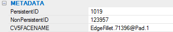
The Metadata section is a list of all the metadata (or attributes) associated with the selected component. Some metadata may be created with subsections to improve legibility.
- PMI Properties
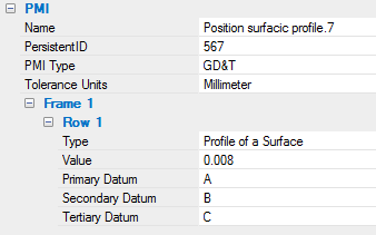
The PMI section provides the semantic meaning of the selected PMI. When the selected PMI refers to one or more topological components, the General Property section is populated with the properties for the first referenced item.
Isolating, Hiding, and Retessellating Geometry
Geometry can be isolated or hidden in two ways:
- Through the context menu on the Model Browser (right-click on an item)
- Through the context menu on the main 3D window (right-click on the geometry and choose isolate, or right-click anywhere and choose isolate to isolate the currently selected geometry).
Once something is isolated or hidden, the performance will usually suffer from a downgrade. It is important to track the isolated performance over different releases of the HOOPS Demonstration Viewer.
Once an object has been isolated or hidden, it should still be selectable, while everything else should be non selectable and invisible. The camera should smoothly change to fit the remaining geometry.
There are two ways to undo an Isolate or Hide operation:
- Right-click on the main 3D window and choose ‘Show All’
- Right-click on a hidden Model Browser item and choose ‘Show’
PMI
When right-clicking a PMI Group in the model browser, you will be presented with two options to “Hide PMI Group” and “Show PMI Group” which will hide or show only the PMI contained in that group. In order to hide or show all the PMI in an entire model you will need to right-click the top-level folder in the model browser. Doing so will present the “Hide All PMI” and “Show All PMI” options.
H-to-hide
Pressing ‘H’ on the keyboard will turn the geometry under the mouse pointer transparent, and change its line color to white. This will also make the hidden geometry non selectable, so that it is possible to select THROUGH an object that has been hidden by pressing H.
Note that it is not possible to use this functionality while in isolate mode.
It is possible to hide multiple pieces of geometry at the same time through this functionality. All the geometry which has been hidden through pressing H will become visible again upon clicking on the background window.
Retessellating
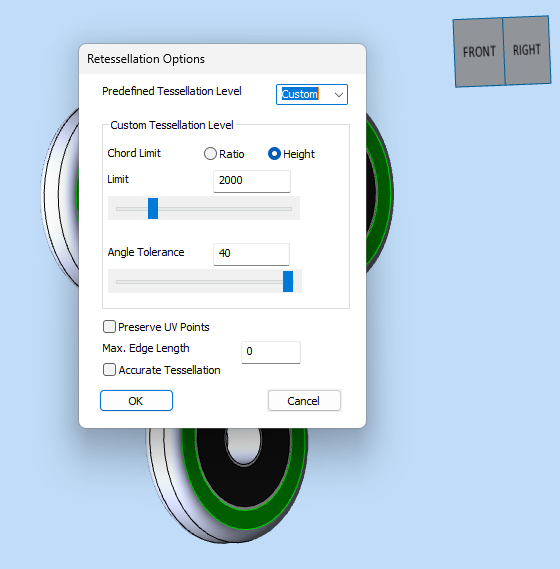
The “Retessellate” context menu option allows you to retessellate a model according to your needs.
A higher tessellation will improve the smoothness and detail of a model at the cost of performance. It is especially noticeable in curved or rounded areas. HDV has a few different pre-configured tessellation levels to choose from, or you may set a custom level:
Retessellation is not available for all geometry types.
Exporting Files
A file export operation can be initiated by pressing CTRL+S or by pressing File/Export. Once one of those two actions has been carried out, the following dialog will appear:
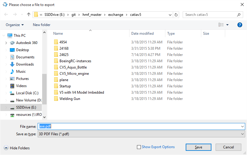
The file name is automatically populated based on the name of the model you are trying to export. Its extension changes automatically if you select a different export type.
If the user checks the “Show Export Options” check box, and then clicks Save, a dialog allowing the user to specify export options for the file that was selected will appear. Clicking Save without checking “Show Export Options” will export the selected file with the export options which were specified last (of the default ones, if they were never specified).
This is the Export Options dialog:
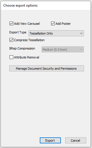
Once a successful export has been completed, the following fields are saved to the preference files, and will be remembered on subsequent export operations, even between different runs of the applications: the type of exports, the export options, the folder in which you saved your last export.
When exporting 3D PDFs, if the user decides to include a View Carousel into the file, all the views related to the models will be present in that carousel. If the model has fewer than 6 views, 7 default views will be automatically generated by the HOOPS Demo Viewer and included into the 3D PDF file.
Once an export operation starts, it cannot be canceled by the user.
Ribbon Explanation
This is a breakdown of the functions exposed through the ribbon, and their description, left to right. These settings are handled on a per-tab basis.
Home ribbon
| Axis triad | Toggles axis triad on and off. ON by default. |
| Nav cube | Toggles navigation cube on and off. ON by default. |
| Home | Smoothly activates the default view for Exchange files. For non-Exchange files it zooms to extent. |
| Model browser | Toggles visibility of the Model Browser panes on and off. ON by default. |
| Properties | Toggles visibility of the Properties pane on and off. ON by default. |
| Rendering modes | Sets the rendering mode. Choices are ‘shaded’, ‘shaded with lines’, ‘tessellated’, ‘hidden line’, and ‘wireframe’. |
| Window background | Changes the window background color. This setting applies to the current tab and to all the tabs which will be then opened. The color setting is saved to the preference file, and will be restored to your last choice the next time you run the application. Clicking on the bottom part of the button allows the user to choose from a color palette or to revert to the default color. |
| Orthographic/perspective camera | Changes the camera projection. The text of the button represents the current camera projection. By default an orthographic projection is used, except for IFC files, which are loaded with a perspective camera. |
| Operators | Allows you to choose the current operator. Default is ‘Orbit’, but you may also choose from ‘Zoom Area’, ‘Turntable’, ‘Fly’, ‘Zoom Fit’, and ‘Point’. |
| Selection mode | Switches between face selection, edge selection or face+edge selection. Defaults to face+edge selection. |
| Markup | The user can use this button to choose one of four types of markup: freehand, circles, rectangles or text. Markups are collected into layers and accessible from the model browser. Markups will disappear once the camera position changes, and can be activated again through the model browser. |
| Measurements | Measurements are available by choosing choose one of four types of measurement operations: length, point to point, feature to feature and angle. All measurements are available to files imported with B-rep data. Only point-to-point to measurement is available for files imported through Exchange, but without B-rep data. All other files do not have access to measurements. Measurements are collected in the model browser, where they can be individually hidden, shown or deleted. It is also possible to hide or show all measurements at once from the Model Browser. |
| Undo | Measurements and markups can be undone while they are being inserted by pressing ESCAPE. Pressing ESCAPE while not inserting a measurement or a markup will delete the markup or measurement you have inserted last. For the purpose of the undo operation, only markups in the active layer are taken into consideration. |
| Repair Mesh | Reorganizes mesh data to help remove visual anomolies. Information about removing T-junctions is available here. |
Rendering Modes Explanations
Shaded: Sets the rendering mode to Phong, turns silhouette edges off. If the loaded model is an IFC model, it turns off hard edges and perimeter edges, and turns line visibility on.
Shaded With Lines: Sets the rendering mode to Phong With Lines, turns silhouette edges off. For IFC models it turns hard edges and perimeter edges on.
Tessellated: Sets the rendering mode to Flat, turns silhouette edges off. Turns edge visibility ON. For IFC models it turns hard edges and perimeter edges on.
Hidden Line: Sets the rendering mode to Fast Hidden Line. Turns edge visibility OFF, and silhouette edges ON. If fixed frame rate is enabled, it disables it and prevents the user from enabling it until when the rendering mode is changed. For IFC models it turns hard edges and perimeter edges on.
Wireframe: Sets the rendering mode to Wireframe, turns silhouette edges off. Turns edge and face visibility OFF. For IFC models it turns hard edges and perimeter edges on.
Operator Explanations
Zoom Area: Click and drag the mouse to perform a zoom based on that area.
Turntable: The turntable operator is an operator which allows the user to orbit the camera along a specific axis. This operator works for both mouse- and touch-driven devices.
Fly: The fly operator is an operator which allows the user to accurately move the camera around the scene. This operator works for both mouse- and touch-driven devices.
Zoom Fit: Zoom fit operator.
Point: Custom operator which allows the user to both select and area select.
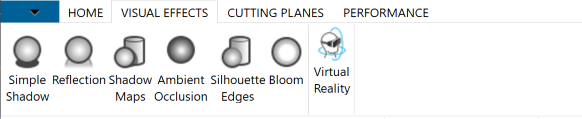
Visual effects ribbon
| Button name | Description |
|---|---|
| Bloom | Toggles the bloom effect on/off. OFF by default. |
| Simple shadow | Toggles simple shadows on/off. OFF by default. |
| Shadow maps | Toggles shadow maps on/off. OFF by default. When enabled, the light in the scene is deleted and replaced with three fixed lights of smaller intensity. When shadow maps are enabled the lights do not follow the camera. Disabling shadow maps deletes the three static lights and reintroduces the previous light, which follows the camera. |
| Reflection | Toggles the reflection plane on/off. OFF by default. |
| Ambient occlusion | Toggles ambient occlusion. OFF by default. |
| Silhouette edges | Toggles silhouette edges on/off. OFF by default. Silhouette Edges are activated automatically whenever the user switches to Hidden Line rendering mode. Since this is done automatically the button on the ribbon does not change states. This automatic action is reverted when the user switches from Hidden Line to a different rendering option. |
| Virtual reality | Enables users to view the model in a VR headset. Users can walk around the model, rotate and move the model around, scale the model, and select/isolate/hide parts. |
Viewing a Model in VR
Users will need to install Steam and SteamVR before using the VR mode in the HDV.
- First, install the Steam application from: http://store.steampowered.com
- Once Steam has been installed, run the application. In the top menu, select Library, go to VR and select “Install SteamVR” and install it on your system.
Currently, the HDV supports the following headsets:
- Oculus Rift
- HTC Vive
For all headsets, the HDV requires two controllers to be connected at all times in order to interact with the model. When the controllers are not connected, you can still view the model in Virtual Reality, but you will not be able to interact with the model.
Using the VR Application
To enable VR you’ll need to have a model loaded in the HDV and a supported VR headset plugged into your computer. Click the Virtual Reality button to enable VR.
The following instructions on how to use the controllers will also be provided in the app when starting Virtual Reality mode:
| Left controller | Holding the grip button down and moving the controller will cause the model to move (orbit and translate) matching the controller movement. When parts of the model are selected, a context menu will appear around the track pad or joystick of the left controller. Pressing the trackpad (or tilting the joystick) in the direction of the desired context menu item will activate it. |
| Right controller | Pressing the trigger will select the part the right controller is pointing to. The name of the selected part will be shown. Holding down the grip button, together with the left button, will scale as you move the two controllers together or apart. |
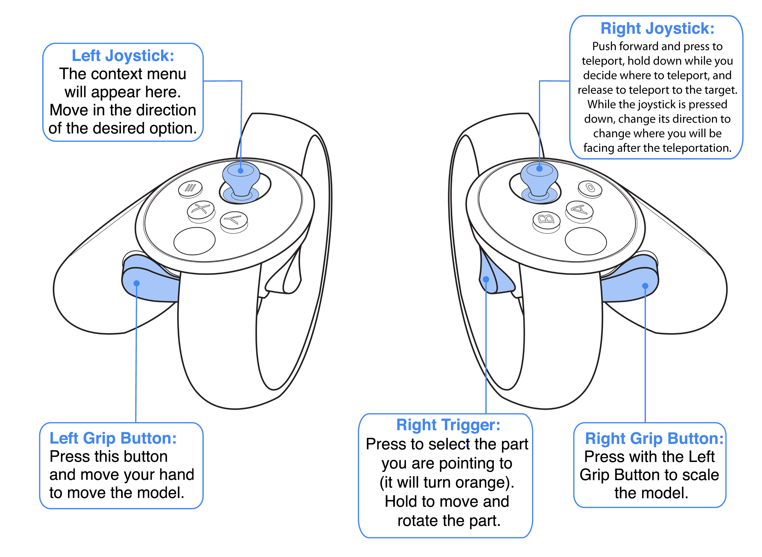
Oculus Rift control scheme
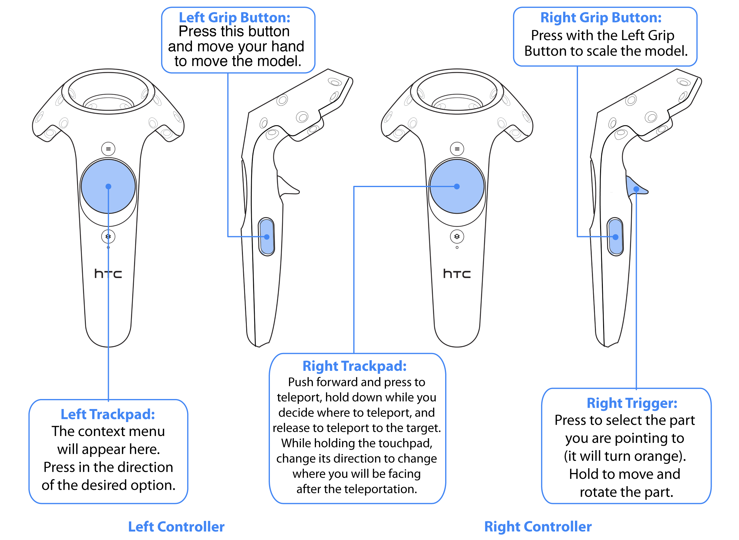
HTC Vive control scheme
While in Virtual Reality mode, the Desktop window of the HDV will show a preview of what the user’s left and right eyes are seeing inside the Virtual Reality headset.
While using the headset, the regular desktop buttons and general mouse-interactivity of the application is suspended. Scaling, translating, and rotating the scene with the left controller is also disabled while geometry is actively being moved by the user. Any changes in the position of geometry will be preserved when the user leaves VR mode and goes back to desktop mode.
Known limitations:
- Hide / Isolate operations, highlights, cutting planes and visual effects will not carry over from Desktop Mode to Virtual Reality Mode
- Some content, such as non-transformable text and patterned lines does not look correct in Virtual Reality
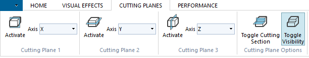
Cutting planes ribbon
| Button name | Description |
|---|---|
| Cutting plane 1 | Inserts a cutting plane with a normal along the indicated axis. |
| Cutting plane 2 | Inserts a cutting plane with a normal along the indicated axis. |
| Cutting plane 3 | Inserts a cutting plane with a normal along the indicated axis. |
| Toggle Cutting Section | If OFF, when clicked it collects the active cutting planes into a single cutting sections. If ON, when clicked it splits the current cutting section into individual cutting planes. By default planes are not collected into a cutting section. |
| Toggle visibility | Toggles the visibility of the geometry representing the planes on/off. ON by default. |
NOTE: The possible choices for cutting plane axis are: X, Y, Z, and From Face. Selecting ‘From Face’ and then activating the cutting plane changes the mode of the application. At this point moving the mouse on the scene will display an indicator of where the place will be positioned. Move the mouse pointer to the desired position and left-click to position the cutting plane.
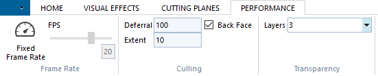
Performance ribbon
| Button name | Description |
|---|---|
| Fixed frame rate | Toggles Fixed Frame Rate mode on/off. OFF by default. It is not possible to turn fixed frame rate on while in the Hidden Line rendering mode. The frame rate target can be set through the slider once Fixed Frame Rate mode has been activated. The slider can range is [0-30], with 0 disabling Fixed Frame Rate mode. While Fixed Frame Rate is active, any transparent geometry is rendered using screendoor while the camera is moved. Moving to and from Fixed Frame Rate will cause the static model to be regenerated. A dialog appears during the regeneration, since this operation can take up noticeable time with large models. |
| Culling options | This sections allows the user to change the default culling options. |
| Transparency layers | This sections allows the user to change how many transparency layers are used. Defaults to 3. |
BIM ribbon
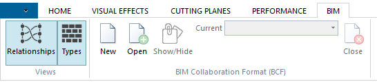
The buttons on the BIM ribbon are only activated when a BIM file format such as IFC or BCF is loaded. The “Relationships” and “Types” buttons toggle visibiliy of those features in the right sidebar.
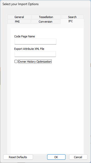
In the IFC file’s Import Options dialog, the Owner History Optimization check box needs to be unchecked in order to import Types data. Otherwise, the Types are not shown in the panel.
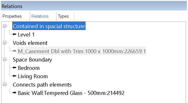
If opening elements are not imported with Exchange import options, those are shown in grey. This means the associated geometry of this node (which is a opening element in IFC) is not available. For example:

Controls
- To expand the relationship tree click the +/- buttons.
- To see relations of any other entity from relations tree, double click on the node.
- Clicking on a model tree node will change the selection in graphics windows. It also populates the associated relations in the panel.
The “Relations” and “Types” sub panels are dockable like other panels in HDV.
Release Notes
HDV 2024.8.0
Introducing new HOOPS Exchange export options:
- Export JT * Wireframe: When exporting JT files from HDV, a specific export option is now available to include wireframes. For more information, please refer to link here. * Version: HDV now provides the option to choose the version of the JT format to export. The current default version is 10.0, and support is also available for versions 9.5 and 8.1. For more information, please refer to link here.
- Export STEP * Format and Editions: HDV now supports multiple editions of STEP AP 242 export. The default format and edition is AP 242 Ed 1, but other editions including AP 242 Ed 2 and 3, AP 203 and AP 214 are available as export options. For more information, please refer to link here. * Semantic PMI: Semantic PMIs can now be exported with the STEP AP 242 format from HDV. For more information, please refer to link here. * Tessellated PMI: A new STEP export option is now available to export PMI as tessellated data. For more information, please refer to link here.
New Experimental Feature:
- Remove T-Junction [Experimental] A new toolbar menu button is available in the HDV toolbar to remove T-junctions from tessellated models. For more information, please refer to link here.
HOOPS Demo Viewer 2024.8.0 updates component libraries to version 2024.8.0.
HDV 2024
HOOPS Demo Viewer 2024 updates component libraries to version 2024.
HDV 2023 SP1
Introducing our newly enhanced search experience, which includes the following new features:
- Exact match: Search for exact matches only by wrapping the search term - or phrase - in quotation marks.
- Fuzzy search: Search results now appear for the closest matches even if no exact matches are found.
- Result filtering: Narrow your search results by section.
HOOPS Demo Viewer 2023 SP1 updates component libraries to version 2023 SP1.
New BIM controls. A new ribbon control and a variety of associated import options related to IFC and BCF models is now available.
HDV 2023
HOOPS Demo Viewer 2023 updates component libraries to version 2023.
HDV 2022
HOOPS Demo Viewer 2022 updates component libraries to version 2022.
HDV 2021
HOOPS Demo Viewer 2021 updates component libraries to version 2021.
HDV 2020 SP2
HOOPS Demo Viewer 2020 SP2 is a bug fix release only.
HDV 2020 SP1
Enhancements
Revit import option. A new import option for the Revit format, HPS::Exchange::ImportOptionsKit::SetRevitPhysicalProperties(), has been introduced. This controls whether Revit physical properties are computed during the reading process and stored as attributes. Related new functions include HPS::Exchange::ImportOptionsKit::UnsetRevitPhysicalProperties, HPS::Exchange::ImportOptionsKit::ShowRevitPhysicalProperties, as well as a new HPS::Exchange::Revit::PhysicalProperties enum.
CatiaV5 materials. CatiaV5 files can now be imported with materials.
HDV 2020
Functional changes
Multiprocess loading. The multiprocess loading option has been removed.
PMI context menu. The PMI context menu has been modified so that it works on PMI groups. Right-clicking on PMI item in the model browser will enable you to show or hide PMI in that group. To hide or show all PMI, perform this operation at the root of the model tree.
Enhancements
Feature tree import. Feature trees can now be extracted for certain formats with B-Rep/Tessellation such as NX or Solidworks.
OBJ export. OBJ files can now be exported in HOOPS Demo Viewer.
HDV 2019 SP2
Functional changes
Context menu. The context menu option “Show All” has been changed to “Reset Visibility”.
Enhancements
StepXML. The StepXML file format can now be imported.
HDV 2019 SP1 U1
HOOPS Demo Viewer 2019 SP1 U1 is a bug fix release only.
HDV 2019 SP1
Enhancements
New import option. A new import option related to sewing called “Compute Non-Solid Shell Orientation” has been added.
Functional Changes
HandlesOperator The HandlesOperator translation function now appends transforms instead of applying a new transform after each action.
HDV 2019
Enhancements
“Handles” Operator Now Available. A “handles” operator has been added. To use the handles operator, load a model and double click on a part. The handles will appear, and you will be able to rotate the model, translate along an axis, and translate along a plane. Once you are satisfied with the position of the geometry you moved, click once on the background to finalize the movement operation and dismiss the handles. If the model you have loaded was imported through Exchange, the change will be reflected in the PRC data and in the component structure. Saving out and reloading a model will preserve the transformations you have applied.
Physically Based Rendering. HOOPS Visualize Desktop now includes a Physically Based Rendering mode. PBR simulates photo-realism by calculating the natural interaction of light and materials. To accommodate this, there have been significant changes to the underlying data and algorithms. PBR is currently offered as a read-only preview for GLTF files imported through HOOPS Exchange.
To try out PBR in the HOOPS Demo Viewer, a sample GLTF file can be downloaded here
New import options. New import options have been added to:
- Force render-mode colors for Rhino files
- Display visible datum for Solidworks files
- Generate grid-aligned tessellation
HDV 2018 SP2
HOOPS Demo Viewer 2018 SP2 is a bug-fix release only.
HDV 2018 SP1
Enhancements
VR mode. Virtual Reality Mode is now available in the Visual Effects ribbon tab. When Virtual Reality mode is enabled, you can interact with the model using a VR headset.
Functional Changes
Visibility settings. Visibility settings have been changed for files imported via HOOPS Exchange: The HOOPS Demo Viewer now uses HPS::Component::Visibility::PreserveAll to preserve the visibility settings for all components in the subtree under the ComponentPath specified by an Isolate/Show/Hide command, regardless of how the visibility was set. Please see the HOOPS Visualize Desktop Programming Guide for specific information on this setting.
HDV 2018
Enhancements
Feature Trees. Feature Trees are now supported for CatiaV5, Unigraphics, and ProE (Creo) files. The Feature Tree will be visible in the Model Browser, where you’ll be able to inspect the CAD features used to create the 3D model. Please see the Import Options sub-section in the <a href=”#opening_file”>Opening Files</a> instructions for more information.
HDV 2017 SP2
Important note: If you have older versions of the HOOPS Demo Viewers and Tetra products currently installed on your machine, the HOOPS Demo Viewer 2017 SP2 installer may uninstall the Tetra license manager from your machine. You’ll have to reinstall the Tetra license manager to fix this.
Enhancements
Relative Orbit. It’s now possible to orbit around the mouse cursor. Please see the <a href=”#multi_function_operator”>multi-function operator section</a> for more information.
Functional Changes
Panning. Panning can no longer be activated by pressing the middle mouse button or by pressing both the left and right mouse buttons at the same time. Please see the <a href=”#multi_function_operator”>multi-function operator section</a> for more information.
HDV 2017 SP1
Enhancements
3D PDF. Users can now export 3D PDFs containing a Part List or a View/PMI table. These options are available for CAD files only. From the Export dialog, click the Show Export Options checkbox; in the Export Options dialog under Advanced Features, click Add Part List or View/PMI table.
HTML Export. HTML Export is now available.
2D export. Users can now define sizes when exporting to 2D image formats.
JT export. File exports to the JT format are now JT version 9.5.
Parasolid XT export. Parasolid XT export is now available for the licensed version of HOOPS Demo Viewer.
HDV 2017
Enhancements
HSF import. When an HSF file is loaded, handles for translation and rotation will appear when geometry is double-clicked.
Multi-process import now available. When importing a file in the HDV or PDV, choose “Show Import Options”. In the “General” tab, you will be able to set the number of processes to be used for that import.
Reflection plane. Improvements in the appearance of the reflection plane.
Selection. Improvements to selection performance.
3MF. Support for 3MF export.
SAT. Support for SAT export for all users.
JT. For non-B-rep data, JT export is now available.
Functional Changes Parasolid export. Parasolid export no longer available.
HDV 2016 SP2
Enhancements
STEP Export. STEP AP 242 Export is now available.
Eye dome lighting. Eye dome lighting is automatically enabled if the loaded file is a point cloud file (XYZ, PTS or PTX).
PMI. PMI is automatically flipped to be readable regardless of which direction you view it from.
Component deletion. You can now delete components from the Model Tree.
Sewing. The Sew import option is exposed for all geometry-based formats.
Conversion tab options. All of the options available in the HOOPS Exchange A3DCopyAndAdaptBrep have been exposed as import options in the Conversion tab of the import option dialog.
Visual effects defaults. To simplify the UI, we have removed all the options for controlling visual effects and used reasonable defaults for all.
Optional tracking. To help us focus our engineering efforts and determine our customers’ needs, the software now includes optional tracking software that allows us to monitor which features our customers like to use. This data is collected anonymously.
New sample files. New sample files were added to the distribution which demonstrate our point cloud support and our material library.
HDV 2016 SP1
Enhancements
Point clouds. Point cloud files are now supported. Users can now load files of the following formats: XYZ, PTS, PTX.
Loading multiple models. Added the ability to load multiple models into the same view by using the Add menu item. CAD models can be added to other CAD models, either at a specific product occurrence, or at the top of the model tree. Non-CAD models can be added to other non-CAD models or to CAD models, but can only be added at the top of the model tree.
PDF security. Added the ability to set PDF security options during export.
Model properties. In model properties, added column for number of parts.
Incremental load. Added support for incremental load. Users can incrementally load SolidWorks, Creo (Pro/E), CATIA V5, and NX (Unigraphics) assemblies. This allows users to load only the structure of an assembly initially, and then selectively load specific parts or subassemblies via the model browser.
3D PDF. HDV will now generate posters by default when exporting to 3D PDF.
IGES files. Added a new tab for IGES files to expose sewing tolerance.
Hidden line rendering. Improved hidden line rendering. I/O options. Expanded import/export options. Users now have access to more options for importing Inventor, ProE, and STEP files. More options have also been added when exporting STEP files. Additionally, several options have been renamed to be more intuitive.
Functional changes
Trial licenses. Users who only have a trial license can now save to any file types except for Parasolid and ACIS.
HDV 2016
Markup. Markups are now available. Users can insert markup in the scene. Available markup types are text, circles, rectangles, and freehand markup. Markups are automatically collected in layers, and are available from the model browser, where they can be individually toggled or deleted.
Measurement. Measurements are now available. Users can insert measurements in the scene. Point to point measurements are always available. Models imported with BRep data are also allowed to measure the length of edges, the length of radii, the shortest distance between planar faces and holes, and the angle between planar faces. Measurements are automatically collected in the model browser, where they can be individually hidden, deleted or shown. Measurements are also automatically exported when a user performs a 3D PDF export – a dedicated measurement view will be created, and the measurements will be available for inspection through the 3D PDF Model Browser.
Redesigned GUI. The ribbon has been redesigned, collapsing several icons in drop down buttons to reduce clutter, and incorporating new icons and a new color palette to improve the look of the application.
I/O file dialogs. Import and Export file dialogs have been standardized to allow users the versatility and familiarity of standard Windows dialogs, while still allowing them to access format specific options.
Feedback. Improved ability to respond to customer feedback. This version of the HDV includes new features which will help us solve any problem customers might encounter. These new features include automatically generated crash dumps, installer logs, versioning, and improved developer tools embedded within the application.
Miscellaneous improvements.
- Some actions are now undoable by pressing the ESC button. The currently supported actions are: loading a file, inserting a markup and inserting a measurement.
- Much improved installer, outfitted with the latest version of the Nimble License Manager will make sure that the HOOPS Demo Viewer plays nice with Tetra 4D products.
- Code signing has been implemented
- Added VRML export
Bug fixes and performance improvements. The new version of the HDV contains a large number of bug fixes, as well as the improved stability and functionalities of the updated versions of HOOPS Visualize Desktop and Exchange it uses. Some of the areas we focused on specifically are:
- Improved presentation and accuracy of model physical properties
- Improved handling of PMI properties and drawing of PMI text
- Improved performance when selecting or highlighting a model
- Improved presentation for high-DPI screens
