Component Hierarchy
HOOPS Visualize Desktop uses a generic component hierarchy to represent third-party CAD models which feature topological entities. The component hierarchy is a way to organize the scene graph uniformly across disparate file formats. It also provides developers the ability to extend the capabilities of our importers, as well as to create entirely new importers in a way that is compatible with the HOOPS Visualize Desktop scene graph. The HOOPS Exchange and Parasolid importers produce HPS::CADModel objects that abstract the structure of the model into a HPS::Component hierarchy.
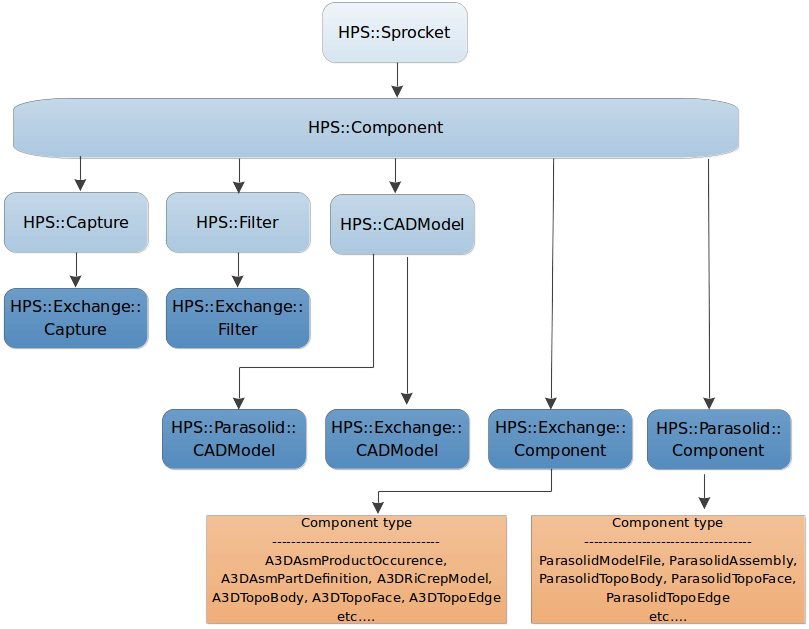
The HPS::Component object hierarchy
The major parts of the hierarchy are described below:
| Object name | Description |
|---|---|
HPS::CADModel |
The root entity of the 3D model. Files loaded with the HOOPS Exchange importer will have a root entity of type HPS::Exchange::CADModel. The Parasolid importer uses HPS::Parasolid::CADModel. |
HPS::Capture |
A specific view of an object, including the camera, materials, transforms, etc. |
HPS::Filter |
A collection of visibility settings for a HPS::CADModel |
HPS::*::Component |
A complex object which can represent a variety of model components, including non-geometric components |
In general, components refer to HOOPS Visualize Desktop objects, whereas entities refer to the underlying object of the model’s native platform. However, there is not a perfect one-to-one mapping between components and entities. For example, some modeling APIs represent faces and edges as two separate entities, but HOOPS Visualize Desktop groups the two into a single shell. For a list of all supported entities and their corresponding components, see the reference manual entry for HPS::Component.
Using a model browser
When loading a model using HOOPS Exchange, a common operation is to navigate the model hierarchy using a tree control. HOOPS Visualize Desktop does not provide such a control as part of its API, but you can see an example of one in use in the WPF or MFC sandboxes.
Utilizing the ComponentPath
A HPS::ComponentPath is an explicit list of components that form a path from an individual component to the top of the scene graph. A HPS::ComponentPath is very similar to a HPS::KeyPath, except that it forms a list of HPS::Component objects instead of HPS::Key objects (key path objects are discussed in this section). If necessary, you can get a component path from a key path by calling HPS::CADModel::GetComponentPath().
When using HPS::CADModel::GetComponentPath(), it is important to understand that only unambiguous portions of paths are returned. For example, consider the cube below – specifically, the edge between the red and green faces:

If you ask HOOPS Visualize Desktop to return a path describing this edge, what should that component path look like? Since the component path is ordered leaf to root, it should start with the edge that was selected and should make its way towards the HPS::CADModel object. But as we go up the hierarchy we find that we have a problem: which face will be part of the path? The red or the green one?
The edge selected belongs to both faces, and there is no information provided to indicate whether the user is interested in the red one, the green one, or neither. The situation is ambiguous.
If you call HPS::CADModel::GetComponentPath() with the HPS::ComponentPath::PathType argument, it will only include unambiguous components in the component path. Therefore the path returned might look something like this:
- Edge / Shell / Connex / Body / RI BRep Model / Part Definition / P. Occurrence / Model
HOOPS Visualize Desktop also provides an option to return a complete component path. What this means is that HOOPS Visualize Desktop will make an assumption as to which face the user needs in the example above. In this case, the returned path will look like this:
- Edge / Co-Edge / Loop / Face / Shell / Connex / Body / RI BRep Model / Part Definition / P. Occurrence / Model
Which face was returned in the above component path? The red or the green one? HOOPS Visualize Desktop returns the face encountered first – therefore, the result is not guaranteed.
Managing Component Visibility
HPS::CADModel and the associated HPS::Component hierarchy provide a convenient interface to visualize, traverse, and interrogate the imported model, but have more complicated visibility management than a standard HOOPS Visualize Desktop segment tree. This is because HPS::CADModel objects can describe multiple views of a single assembly, each of which may contain different visibility and material settings. Thus, the visibility of a given component and its underlying geometry is conditional depending on its view. Furthermore, the types of geometry (edges, faces, lines, etc.) that are visible are also determined by how the view is being rendered.
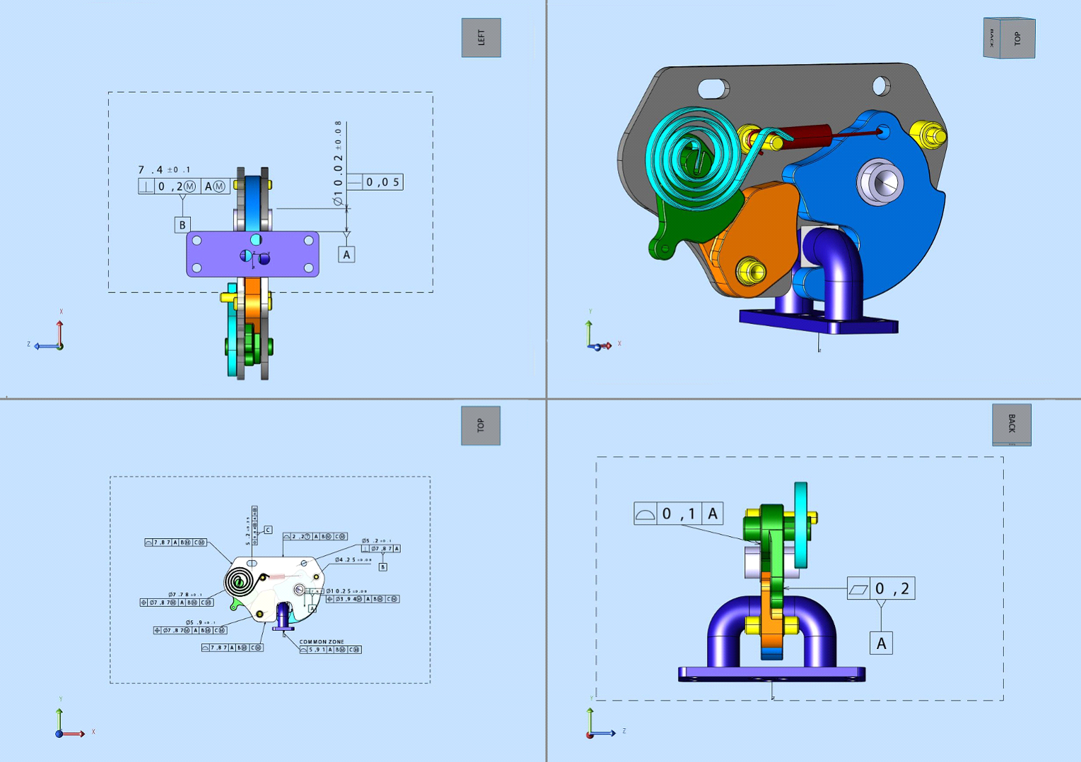
Four views activated from the same CADModel. Each view shows different visibility settings for sub-assemblies and contains different markup.
The mechanism for changing the visibilities of HPS::CADModel components after import is available through the HPS::ComponentPath and HPS::ComponentTreeItem classes. HPS::ComponentPath objects describe a unique path from the component of interest to the root of your HPS::CADModel. HPS::ComponentTreeItem objects are intended to represent a unique component path in a GUI tree control. Each of these classes contain Show(), Hide(), Isolate(), and ResetVisibility() functions which let you control the visibility of the related components.
These functions not only act on a specific component path, but are also bound to a single view at a time, which enables visibility states of the model to be modified differently in several views simultaneously. The changes made by these functions are intended to be transient in nature. They are purely visual and will not be encoded in the structure of the model if exported.
Hide() forces the visibility of the associated HPS::ComponentPath and all components under this path to invisible. Any visibility changes made previously at or below this path are flushed. Any visibility changes made subsequently at or below this path are honored unless they are redundant.
Show() makes the associated ComponentPath visible while components that exist underneath the chosen path retain the visibility of previous Hide(), Show(), or Isolate() calls and otherwise preserve the visibility defined for the components by this view. Any visibility changes made subsequently at or below this path are honored unless they are redundant.
Isolate() invokes a Hide() call at the root of the model and a Show() at the leaf of the chosen path. All rules stated for Show() apply under the leaf of the chosen path while similarly all rules stated for Hide() apply under the root component.
ResetVisibility() reverts the visibility of components at or below the associated ComponentPath back to what the model dictates for the associated view. Effects of all previous Hide() / Show() calls at or below this point should be gone.
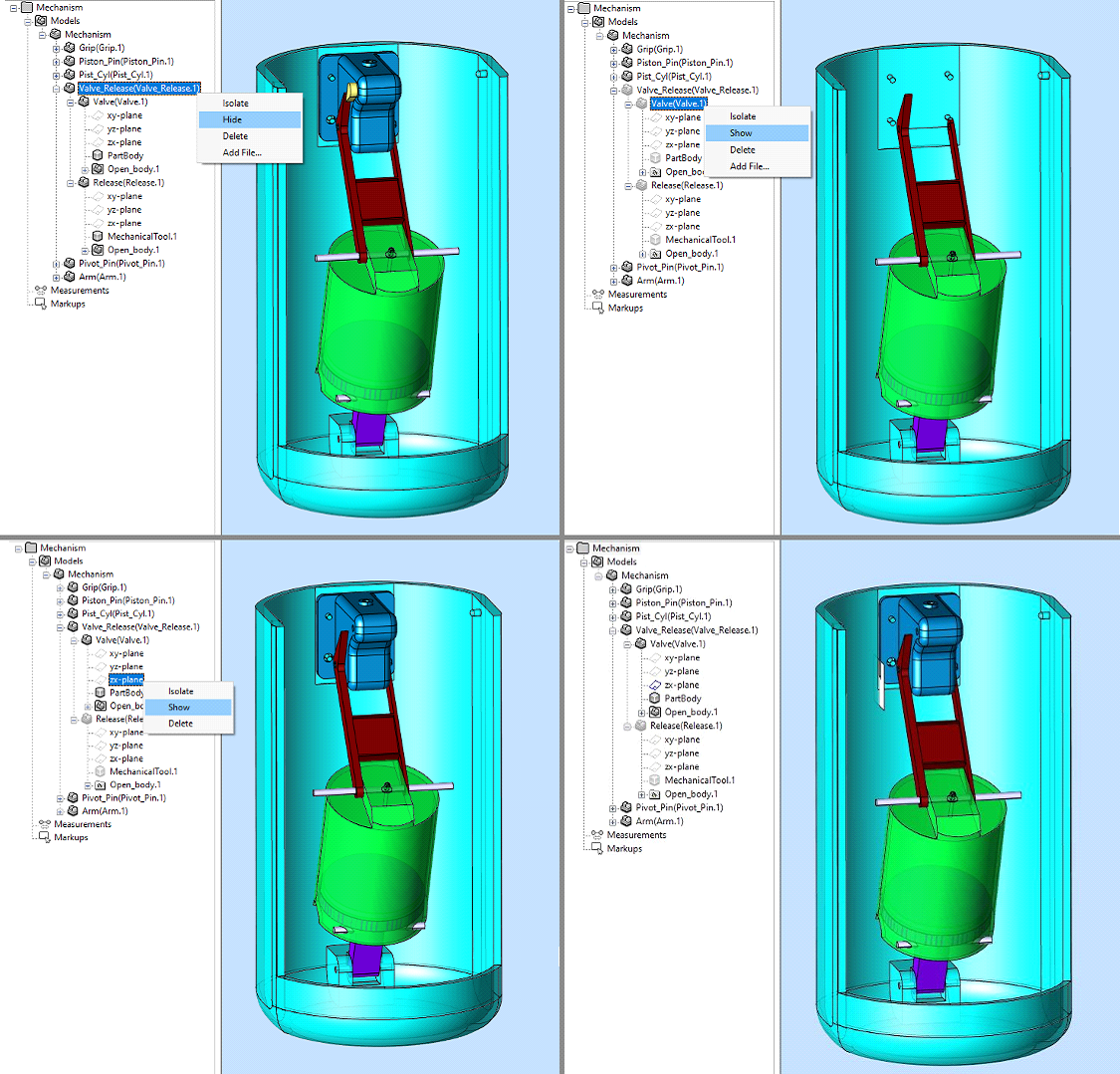
Utilizing ComponentTreeItems to perform nested hides and shows progressing from top left to bottom right. In the top left image the “Valve_Release” assembly is about to be hidden. In the top right the ”Valve” child of ”Valve_Release” is about to be shown. In the lower left image the ”Valve” sub-assembly has been shown and a construction geometry underneath that component is about to be shown. The bottom right image shows the final visibility state with only the ”zx-plane” construction geometry shown.
Limitations
- Geometry modified by
HPS::ComponentPath::Show(),HPS::ComponentPath::Hide(), andHPS::ComponentPath::Isolate()may not interact properly with other transparent geometry contained in the scene. - If
HPS::ComponentPath::Isolate()is called on an assembly containing only hidden subcomponents (and subcomponents visibility is preserved) the scene may become empty (unless the part being isolated contains geometry directly at the specified path). - Components shown using
ShoworIsolatemay not preserve post-process effects used in the scene.
Interacting With Highlights
Show, Isolate, and Hide are implemented internally with highlights. Thus, extra care must go into making sure other highlights interact properly in a scene that invokes the aforementioned functions. When using highlights in combination with Show, Hide, and Isolate, please utilize the following rules:
- Any highlight under a
HPS::ComponentPathhidden by Hide() will not appear regardless of style or overlay. - Any highlight under a
HPS::ComponentPathshown by Show() should appear as long as the highlight uses the overlayHPS::Drawing::Overlay::InPlace. - Styles used by highlights under a shown component should not define their own visibility settings as these will conflict with the visibilities of
Show().
Show/Hide/Isolate Example
The following example shows the process of loading a file through sprk_exchange, using the resulting HPS::CADModel to create multiple views, and using component visibility functions in combination with highlights to display different content on each view.
First, we start by loading our file through sprk_exchange and setting up our views to each take up a quarter of our window. For this example we are using our Micro Engine model, but setup should be similar for other datasets.
// import the file including hidden objects and construction geometry
HPS.Exchange.ImportOptionsKit importOptions = HPS.Exchange.ImportOptionsKit.GetDefault();
importOptions.SetHiddenObjects(true);
importOptions.SetConstructionAndReferences(true);

HPS.Exchange.ImportNotifier notifier = HPS.Exchange.File.Import(filename, importOptions);
notifier.Wait();

// use the CADModel's default capture in four different views
HPS.Layout layout = HPS.Factory.CreateLayout();
HPS.Exchange.CADModel cadModel = notifier.GetCADModel();

View bottomLeft = cadModel.ActivateDefaultCapture();
layout.AttachViewFront(bottomLeft, new HPS.Rectangle(-1, 0, -1, 0));

View bottomRight = cadModel.ActivateDefaultCapture();
layout.AttachViewFront(bottomRight, new HPS.Rectangle(0, 1, -1, 0));

View topLeft = cadModel.ActivateDefaultCapture();
layout.AttachViewFront(topLeft, new HPS.Rectangle(-1, 0, 0, 1));

View topRight = cadModel.ActivateDefaultCapture();
layout.AttachViewFront(topRight, new HPS.Rectangle(0, 1, 0, 1));

canvas.AttachLayout(layout);
Next, we modify the visibilities of component paths within the different views to achieve different visual states:
// get the root product occurrence
HPS.Component rootPocc = cadModel.GetSubcomponents()[0];
HPS.Component firstChildPocc = rootPocc.GetSubcomponents()[0];

// in the bottom left view (layer 3) hide the first child of the root product occurrence
HPS.ComponentPath pathTofirstChildPocc = new ComponentPath();
pathTofirstChildPocc.Append(firstChildPocc);
pathTofirstChildPocc.Append(rootPocc);
pathTofirstChildPocc.Append(cadModel);
pathTofirstChildPocc.Hide(canvas, 3);

// in the bottom right view (layer 2) isolate the first child of the root product occurrence
pathTofirstChildPocc.Isolate(canvas, 2);

// in the top left view (layer 1) show some of the first child's hidden construction geometry in addition to isolating it
HPS.Component firstChildPart = firstChildPocc.GetSubcomponents()[0];

// this assumes the first 3 child components of the part contain construction geometry
HPS.Component [] partSubcomponents = firstChildPart.GetSubcomponents();
for (int i = 0; i < 3; ++i)
{
    HPS.ComponentPath pathToHiddenConstruction = new HPS.ComponentPath();
    pathToHiddenConstruction.Append(partSubcomponents[i]);
    pathToHiddenConstruction.Append(firstChildPart);
    pathToHiddenConstruction.Append(pathTofirstChildPocc);
	pathToHiddenConstruction.Show(canvas, 1);
}
pathTofirstChildPocc.Isolate(canvas, 1);

// in the top right view (layer 0) isolate the first child and apply a highlight
pathTofirstChildPocc.Isolate(canvas, 0);

// this attempts to make a style with green faces and red lines
// however if the view doesn't have lines, the lines color won't apply
// or if the view doesn't show faces, the face color won't apply
SegmentKey highlightSource = topLeft.GetSegmentKey().Subsegment();
highlightSource.GetMaterialMappingControl().SetFaceColor(new HPS.RGBAColor(0, 1, 0)).SetLineColor(new HPS.RGBAColor(1, 0, 0));
canvas.GetPortfolioKey().DefineNamedStyle("my_style", highlightSource);

HighlightOptionsKit highlightOptions = new HighlightOptionsKit();
highlightOptions.SetStyleName("my_style").SetOverlay(Drawing.Overlay.InPlace);
pathTofirstChildPocc.Highlight(canvas, 0, highlightOptions);
At the end of this procedure we end up with the following scene:
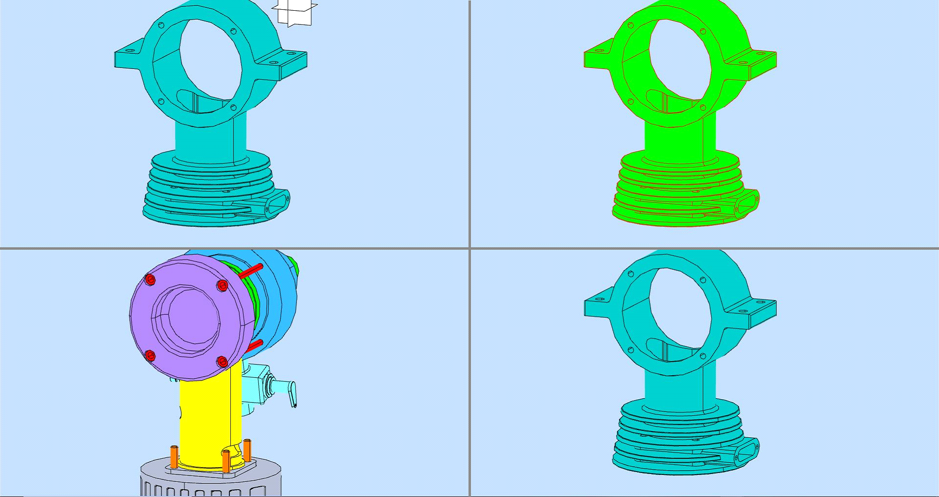
This screenshot demonstrates using the component visibility functions across multiple views. The bottom left view shows the model with a part hidden. The bottom right view isolates the part that was missing in the bottom left panel. The top left view shows that same isolated part with additionally shown construction geometry. The top right shows the same part isolated with an additional highlight.
Using Transforms With Components
When working with components of types Exchange, Parasolid, and ExchangeParasolid, there are two data layers associated with any model: the HOOPS Visualize Desktop scene graph, and the underlying PRC data. Making changes to the HOOPS Visualize Desktop scene graph may produce a distinct visual result, but generally does not modify the PRC. For example, if you apply a transform to a segment which contains part of an Exchange model, then save the file, that transform will not be present in the saved model.
To make a transform to both the scene graph and to the PRC data, use HPS::CADModel::SetTransform() or HPS::CADModel::AddTransform(). The transform will be applied both visually and to the underlying native data.
NOTE: When you apply a transform using HPS::CADModel::SetTransform(), the new transform will REPLACE any existing transforms set on that component. When you apply a transform using HPS::CADModel::AddTransform(), the new transform is APPENDED to the existing transform.
Only certain types of components can have transforms applied to them:
- For Exchange components, valid choices are components of type
HPS::CADModel::ComponentType "ExchangeProductOccurrence", or components which have the maskHPS::CADModel::ComponentType "ExchangeRepresentationItemMask"- For Parasolid components, valid choices are components of any of these types:
HPS::CADModel::ComponentType,HPS::CADModel::ComponentType, andHPS::CADModel::ComponentType
Deinstancing Components
Deinstancing a component refers to analyzing a geometry’s HPS::ComponentPath to determine the level at which changes can be made without interefering with other instanced geometry. This is done using HPS::Factory::DeInstanceComponent, which is available for components of types Exchange, Parasolid, and ExchangeParasolid.
For example, imagine a model of a car which contains four wheels. Each wheel is just an instance of one original wheel geometry. When a user wants to move a wheel, setting a transform on the wheel itself will cause all four wheels to move.
To move just one wheel, you can collect a HPS::ComponentPath for the wheel you are interested in, then call HPS::Factory::DeInstanceComponent().
This function will analyze the path and return a component along it at which level it is safe to apply a transform, such that only the selected wheel will be affected.
Example usage:
    // a user selects a wheel on the screen through a mouse
    SelectionOptionsKit selection_options;

    HPS::SelectionResults results;

    HPS::SprocketPath mySprocketPath(myCanvas);

    if (myWindowKey.GetSelectionControl().SelectByPoint(Point(0, 0, 0), selection_options, results) > 0) {
        // we obtain a keypath from the selection results
        HPS::SelectionItem item = results.GetIterator().GetItem();

        HPS::KeyPath path_to_selection;

        item.ShowPath(path_to_selection);

        // using the CADModel, we obtain a ComponentPath from the KeyPath
        HPS::ComponentPath component_path = myCADModel.GetComponentPath(path_to_selection);

        // we figure out at which level is appropriate to insert a transform, so that only the instance of the wheel I selected is
        // affected
        HPS::Component transform_target = HPS::Factory::DeInstanceComponent(component_path);

        // we apply the transform
        HPS::MatrixKit transform;
        transform.Translate(5, 0, 0);
        transform_target.SetTransform(transform);
        myCanvas.Update();
    }
    // a user selects a wheel on the screen through a mouse
    SelectionOptionsKit selection_options = new SelectionOptionsKit();

    HPS.SelectionResults results;

    HPS.SprocketPath mySprocketPath = new SprocketPath(myCanvas);

    if (myWindowKey.GetSelectionControl().SelectByPoint(new Point(0, 0, 0), selection_options, out results) > 0)
    {
        // we obtain a keypath from the selection results
        HPS.SelectionItem item = results.GetIterator().GetItem();

        HPS.KeyPath path_to_selection;

        item.ShowPath(out path_to_selection);

        // using the CADModel, we obtain a ComponentPath from the KeyPath
        HPS.ComponentPath component_path = myCADModel.GetComponentPath(path_to_selection);

        // we figure out at which level is appropriate to insert a transform, so that only the instance of the wheel I selected is affected
        HPS.Component transform_target = HPS.Factory.DeInstanceComponent(component_path);

        // we apply the transform
        HPS.MatrixKit transform = new MatrixKit();
        transform.Translate(5, 0, 0);
        transform_target.SetTransform(transform);
        myCanvas.Update();
    }

