Shells
A shell is a collection of faces, edges, and vertices that form a 3D object. Shells are the basic building block for most HOOPS Visualize Desktop models. Anything from a single triangle to the most complex model can be represented using a shell. It is the most flexible component in terms of what you are able to do with it. While simpler structures, such as polygons do exist, the advantages of using a shell are the following:
- are considerably faster to render
- can be smooth-shaded
- can be used as a selection mechanism for collision detection
- support advanced rendering capabilities, such as texture mapping and cut edges and faces
- potentially use less memory in the Database as vertices can be shared among faces
- vertex markers and silhouette/perimeter/hard/adjacent edges are available
- attributes can be set on sub-parts
A shell can be used to represent any 2D or 3D object that is described by a collection of polygons. For example, 3D surfaces are typically tessellated into a collection of triangles - thus, a shell is the appropriate primitive. All of these characteristics make a shell the most versatile type of geometry in HOOPS Visualize Desktop.
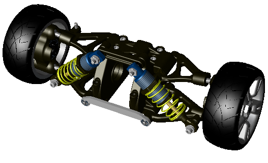
Shells are used as the basic building block for most models
Specifying Shells
Shells are specified using two arrays - an array of points called the point list, and an array of indices into the point array, called the face list. A separate array of points is used so that faces of the shell can share points with one another. For example, when you define a cube, each vertex is shared by three different faces - so only eight vertices are needed to define all six faces. If you defined the same cube using separate polygons (each with their own vertices), then each polygon would require storage for four points, for a total of 24 points stored in the database.
The face list is an array of integers. The first integer is the number of vertices in the first face, followed by an integer for each vertex, which are indices into the point array. For example, if the face list contains [3 0 1 2], then a triangle is formed from the first three points in the point array. The next array index in the face list starts another face, and so on.
Each face must be planar - all its vertices must lie in the same plane. In addition, the edges of a face must not intersect one another. Finally, all faces in a shell must have the same handedness, that is, the points must all be defined in the same direction (clockwise or counterclockwise), as viewed from outside the shell. For a discussion on handedness see this section. Other than that, the definition of shells is flexible. The faces do not even have to be connected, edges can share more than one face, and faces can contain holes.
There are various ways to specify the shell data for HOOPS Visualize Desktop. An HPS::ShellKit is the most advantageous if there is much data to specify, as everything will be entered into the Database in a transactional way. Alternatively, the vertex and face data can be specified using primitive arrays or a combination of PointArray and IntArray. Here is a simple example of the code you would write to create a cuboid of size 2 centered at [1, 1, 1] with a HOOPS Visualize Desktop shell primitive:
    Point points[8] = {Point(0, 0, 0),
                       Point(2, 0, 0),
                       Point(2, 2, 0),
                       Point(0, 2, 0),
                       Point(0, 0, 2),
                       Point(2, 0, 2),
                       Point(2, 2, 2),
                       Point(0, 2, 2)};

    int faceList[30] = {4, 0, 1, 2, 3, 4, 1, 5, 6, 2, 4, 5, 4, 7, 6, 4, 4, 0, 3, 7, 4, 3, 2, 6, 7, 4, 0, 4, 5, 1};

    mySegmentKey.InsertShell(8, points, 30, faceList);
HPS.Point[] points = { new HPS.Point(0, 0, 0), new HPS.Point(2, 0, 0), new HPS.Point(2, 2, 0), new HPS.Point(0, 2, 0),
        new HPS.Point(0, 0, 2), new HPS.Point(2, 0, 2), new HPS.Point(2, 2, 2), new HPS.Point(0, 2, 2) };

int[] faceList = {  4, 0, 1, 2, 3,
                    4, 1, 5, 6, 2,
                    4, 5, 4, 7, 6,
                    4, 4, 0, 3, 7,
                    4, 3, 2, 6, 7,
                    4, 0, 4, 5, 1 };

mySegmentKey.InsertShell(points, faceList);
Setting Normals
When using lighting, the vertices of your shells need to have normals associated with them in order for HOOPS Visualize Desktop to calculate a final color for the shell. If you do not provide normals, HOOPS Visualize Desktop will approximate them by averaging the normal vectors for each face that shares a particular vertex. However, even for simple shapes such as spheres and cylinders, this average may not appear visually realistic, and can produce lighting anomalies. To avoid this problem, you can set normal vectors explicitly. Normals are typically passed to HOOPS Visualize Desktop in a list and are set all at once on the shell beginning at a face or vertex index that you specify.
For the purposes of smooth shading, it is best to set normal vectors on the vertices, but you can also set normal vectors on the faces of a shell, and HOOPS Visualize Desktop will use an average of these normals for smooth shading. You can also unset a normal so that it will revert to its value as calculated by HOOPS Visualize Desktop.
The following code snippet offers an example for setting normals on a shell:
    HPS::ShellKit myShellKit;

    // for smooth shading, set normals on vertices
    myShellKit.SetVertexNormalsByRange(0, normalArray);

    // if your model will be flat shaded, set normals on faces
    myShellKit.SetFaceNormalsByRange(0, normalArray);

    // you may also unset normals in a similar way
    myShellKit.UnsetFaceNormals();
HPS.ShellKit myShellKit = new HPS.ShellKit();

// for smooth shading, set normals on vertices
myShellKit.SetVertexNormalsByRange(0, normalArray);

// if your model will be flat shaded, set normals on faces
myShellKit.SetFaceNormalsByRange(0, normalArray);

// you may also unset normals in a similar way
myShellKit.UnsetFaceNormals();
NOTE: For convenience, there are many variants of these functions, which are all listed in the HPS::ShellKit reference manual.
Shells With Holes
HOOPS Visualize Desktop supports shells with holes. To do this, simply negate the first parameter in the face list for the face which you want to be a hole. Note that the first face specified cannot be a hole. The example below builds a simple square shell with a square hole:
    Point points[8] = {Point(0, 0, 0),
                       Point(3, 0, 0),
                       Point(3, 3, 0),
                       Point(0, 3, 0), // perimeter
                       Point(1, 1, 0),
                       Point(2, 1, 0),
                       Point(2, 2, 0),
                       Point(1, 2, 0)}; // hole

    int faces[10] = {4, 0, 1, 2, 3, -4, 4, 5, 6, 7}; // negated parameter indicates this face is a hole

    mySegmentKey.InsertShell(8, points, 10, faces);
HPS.Point[] points = { new HPS.Point(0, 0, 0), new HPS.Point(3, 0, 0), new HPS.Point(3, 3, 0), new HPS.Point(0, 3, 0),    // perimeter
                   new HPS.Point(1, 1, 0), new HPS.Point(2, 1, 0), new HPS.Point(2, 2, 0), new HPS.Point(1, 2, 0)  }; // hole

int[] faces = {  4, 0, 1, 2, 3,
                -4, 4, 5, 6, 7  }; // negated parameter indicates this face is a hole

mySegmentKey.InsertShell(points, faces);
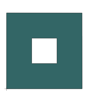
The code above produces this simple shell with a hole
When specifying vertices for shells, their position in the point list is not important. However, the face list ordering is important because it determines how the vertices are connected and how each face is wound. As long as the face list specifies vertices in a consistent fashion to generate appropriate winding and normals, your shell will appear correctly in HOOPS Visualize Desktop.
(Please note, it isn’t currently possible to add holes to already existing faces in HOOPS Visualize Desktop – faces with holes can only be created during their initialization.)
Editing Shells
After insertion, both the vertices and the face list can be changed. Using the HPS::ShellKey, the modification takes place via deletion, insertion, or replacement of points or faces. This section demonstrates those operations, starting with the shell below.
    Point points[12] = {Point(-1, 0, 0),
                        Point(0, 0, 0),
                        Point(0, 1, 0),
                        Point(-1, 1, 0),
                        Point(0, 0, 0),
                        Point(1, 0, 0),
                        Point(1, 1, 0),
                        Point(0, 1, 0),
                        Point(1, 0, 0),
                        Point(2, 0, 0),
                        Point(2, 1, 0),
                        Point(1, 1, 0)};

    int faces[15] = {4, 0, 1, 2, 3, 4, 4, 5, 6, 7, 4, 8, 9, 10, 11};

    mySegmentKey.InsertShell(12, points, 15, faces);
HPS.Point[] points = { new HPS.Point(-1, 0, 0), new HPS.Point(0, 0, 0), new HPS.Point(0, 1, 0), new HPS.Point(-1, 1, 0),
                       new HPS.Point( 0, 0, 0), new HPS.Point(1, 0, 0), new HPS.Point(1, 1, 0), new HPS.Point( 0, 1, 0),
                       new HPS.Point( 1, 0, 0), new HPS.Point(2, 0, 0), new HPS.Point(2, 1, 0), new HPS.Point( 1, 1, 0) };

int[] faces = { 4, 0, 1, 2, 3,
                4, 4, 5, 6, 7,
                4, 8, 9, 10, 11 };

mySegmentKey.InsertShell(points, faces);
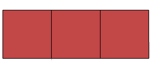
The shell produced by the code
Note that the code above specifies several redundant vertices. While it may be simpler to understand for this short example, generally this is not ideal because memory is wasted on the extraneous vertices. The same shell above could be specified in a more compact way, as shown in the following snippet:
    Point points[8] = {Point(-1, 0, 0),
                       Point(0, 0, 0),
                       Point(0, 1, 0),
                       Point(-1, 1, 0),
                       Point(1, 0, 0),
                       Point(1, 1, 0),
                       Point(2, 0, 0),
                       Point(2, 1, 0)};

    int faceList[15] = {4, 0, 1, 2, 3, 4, 1, 4, 5, 2, 4, 4, 6, 7, 5};
HPS.Point[] points = { new HPS.Point(-1, 0, 0), new HPS.Point(0, 0, 0), new HPS.Point(0, 1, 0), new HPS.Point(-1, 1, 0),
                       new HPS.Point( 1, 0, 0), new HPS.Point(1, 1, 0), new HPS.Point(2, 0, 0), new HPS.Point( 2, 1, 0) };

int[] faceList = { 4, 0, 1, 2, 3,
                   4, 1, 4, 5, 2,
                   4, 4, 6, 7, 5 };
This code is more efficent, however, there is one case where using redundant vertices may be a good choice. When coloring a shell, redundant vertices will produce a hard color change between edges. The condensed vertex method will result in a blended effect across edges.
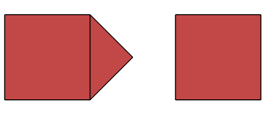
Deleting Faces and Points
To delete a face, simply call SegmentKey.EditFacelistByDeletion. Note that by deleting the middle face of the shell, it is visually made into two separate parts. However, logically, both parts belong to the same shell. When a face is deleted, the points associated with that face are still part of the shell. There is simply no face associated with the vertices.
    // deletes 1 face, starting at offset 1
    myShellKey.EditFacelistByDeletion(1, 1);
// deletes 1 face, starting at offset 1
myShellKey.EditFacelistByDeletion(1, 1);
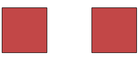
The middle face is deleted
The same operation could have been done using EditPointsByDeletion. However, when deleting points, the face associated with the points is also deleted from the face list. It is important to note that while originally, the face list had 15 elements, it will have 10 after the middle 4 points are deleted (the face-length specifier is also deleted for a total of 5). The remaining points are shifted down in the point list to replace the deleted points. Thus, they can no longer be indexed by their original positions in the array.
Inserting Faces and Points
When inserting points, HOOPS Visualize Desktop will do extra processing to ensure that your original face list will remain coincident will the original points. Thus, if a point was inserted at the beginning of the point list, the face list parameters would be adjusted to account for the change. Adding a new point is not complicated. Using the shell above as a starting point, a new face is created by the code below:
    PointArray insertedPoints(1);
    insertedPoints[0] = Point(0.5f, 0.5f, 0);

    int insertedFacelist[] = {3, 1, 8, 2};

    myShellKey.EditPointsByInsertion(8, insertedPoints);
    myShellKey.EditFacelistByInsertion(1, 4, insertedFacelist);
HPS.Point[] insertedPoints = new HPS.Point[1];
insertedPoints[0] = new HPS.Point(0.5f, 0.5f, 0);

int[] insertedFacelist = { 3, 1, 8, 2 };

myShellKey.EditPointsByInsertion(8, insertedPoints);
myShellKey.EditFacelistByInsertion(1, insertedFacelist);
Note that when calling EditFacelistByInsertion, the first parameter indicates the position within the face list to insert the new face, while the second parameter indicates number of array elements you’re passing.
The middle face has been inserted in a different way
Setting Materials at the Entity Level
To optimize performance, developers are encouraged to structure the HOOPS Visualize Desktop scene graph such that all attributes are specified at the segment level. Geometry with similar attributes is then grouped into the same segment. However, for complex scenes, or scenes where fine-tuned control is needed, this is not always possible. For these cases, HOOPS Visualize Desktop offers an interface that allows you to modify attributes at the geometry or subentity level.
Local settings always override higher-level settings, thus, when setting a material on an individual shell, that material will take precedence over any material set (or inherited) at the segment level. However, the process for setting a material at the geometry level is more complex. You must define a material - a simple call to HPS::RGBAColor won’t work.
See also:
- A discussion on defining materials in this section
- Examples of setting materials on various entities and subentities can be found in the applying materials page.
- You may also wish to refer to the shell attributes code sample
Setting Attributes on Shells at the Sub-Entity Level
Shell sub-entities are the faces, vertices, and edges that make up the shell. These attributes can be controlled at different levels of granularity. For example, vertex colors can be set individually, or at the segment level. The example below demonstrates how to set vertex colors.
    HPS::RGBAColor vertexColors[4];

    vertexColors[0] = RGBAColor(0, 0, 0, 1);
    vertexColors[1] = RGBAColor(0.25, 0.75, 0.5, 1);
    vertexColors[2] = RGBAColor(0.75, 0, 0, 1);
    vertexColors[3] = RGBAColor(1, 1, 1, 1);

    myShellKey.SetVertexRGBAColorsByRange(0, 4, vertexColors);
HPS.RGBAColor[] vertexColors = new HPS.RGBAColor[4];

vertexColors[0] = new HPS.RGBAColor(0, 0, 0, 1);
vertexColors[1] = new HPS.RGBAColor(0.25f, 0.75f, 0.5f, 1);
vertexColors[2] = new HPS.RGBAColor(0.75f, 0, 0, 1);
vertexColors[3] = new HPS.RGBAColor(1, 1, 1, 1);

myShellKey.SetVertexRGBAColorsByRange(0, vertexColors);
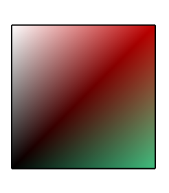
Assigning color to vertices results in a blended effect
Face Color
It is also possible to set color for individual faces. Imagine you had a black cube and you’d like to color three of the faces orange. To do this, you could make a call to set the face color by range:
myShellKey.SetFaceRGBColorsByRange(0, 3, HPS::RGBColor(1, 0.5f, 0));
myShellKey.SetFaceRGBColorsByRange(0, 3, new HPS.RGBColor(1, 0.5f, 0));
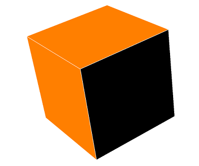
Assigning color to individual faces
Further examples of setting color on particular faces of a shell can be found in the applying materials page.
Face Visibility
Face visibility for shells can be enabled or disabled using the HPS::VisibilityControl. This is a segment-level operation:
    mySegmentKey.GetVisibilityControl().SetFaces(false); // disables rendering of faces
    mySegmentKey.GetVisibilityControl().SetFaces(true); // enables rendering of faces
mySegmentKey.GetVisibilityControl().SetFaces(false); // disables rendering of faces
mySegmentKey.GetVisibilityControl().SetFaces(true);  // enables rendering of faces
This operation applies visibility to the entire shell - in fact, all facetted geometry in the segment and child segments is affected by this setting. But what if you want to make only certain faces of a shell invisible? To do this, you need the shell’s key. Then, you can set the face visibilities by index or by range. Continuing with the cube example from before, you could disable visibility for three of the faces with a similar call:
myShellKey.SetFaceVisibilitiesByRange(0, 3, false);
myShellKey.SetFaceVisibilitiesByRange(0, 3, false);
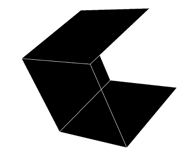
Visibilty disabled for some faces
Alternatively, you could use a material palette and apply a completely transparent material to the appropriate faces, though this is more complex to set up.
Invisible faces are not generally selectable, however, you can force them to be selectable using the special selection setting ForcedOn.
Setting Edge Attributes in Shells
In general, edge attributes are set at the segment level using the HPS::EdgeAttributeControl, though edge color is set using the HPS::MaterialMappingControl.
mySegmentKey.GetMaterialMappingControl().SetEdgeColor(HPS::RGBAColor(1, 0, 0));
mySegmentKey.GetMaterialMappingControl().SetEdgeColor(new HPS.RGBAColor(1, 0, 0));
Vertex Markers
The vertices of a shell are represented by markers. Among other things, the marker symbol, size, and visibility may be adjusted to achieve various effects. Our section on markers has more details.
For most uses of shells, it is common to turn off the visibility of vertices. However, vertices can be used in special situations to represent the shell data as a point cloud. This is also a good alternative when you would otherwise need to render an large number of individual markers because drawing shell vertices is hardware accelerated whereas drawing a set of markers is not. To achieve this, make the vertices visible with edges and faces invisible. Other potential uses include providing highlight feedback during user selection, or providing ‘handles’ for the user to more easily select vertices.
mySegmentKey.GetVisibilityControl().SetVertices(true).SetEdges(false).SetFaces(false);
mySegmentKey.GetVisibilityControl().SetVertices(true).SetEdges(false).SetFaces(false);
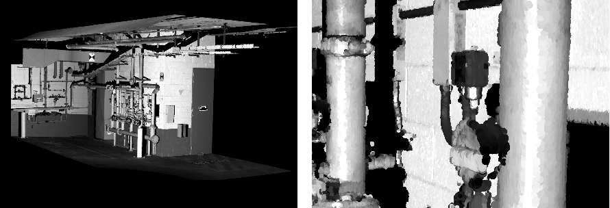
Vertex markers can also be used as point splats. In point splatting, large numbers of densely clustered points are rendered such that they appear as a smooth surface. When zooming in and out, the point splats scale accordingly, continuing to give the impression that one is looking at a surface. This type of behavior is commonly used in laser scan datasets which consist of huge number of densely packed sampled points. For point splatting to be effective, a large number of markers must be rendered in a scene. This can be performance intensive, especially when zooming in and interacting with the object.
When rendering vertices, it is important to choose a proper glyph when depending on hardware acceleration to make your scene interactive. HPS::Glyph::Default::Dot, HPS::Glyph::Default::SolidBox, and HPS::Glyph::Default::SolidCircle can take advantage of acceleration. Note that hardware acceleration is only available in the OpenGL2 and DX11 driver interfaces.
In order to achieve the proper scaling effect when zooming, you should set your markers to scale with the camera position by setting their units to be in WorldSpace.
mySegmentKey.GetMarkerAttributeControl().SetSize(0.25f, HPS::Marker::SizeUnits::WorldSpace);
mySegmentKey.GetMarkerAttributeControl().SetSize(0.25f, HPS.Marker.SizeUnits.WorldSpace);
An example of a point splat rendering is shown below:
3D Markers
HOOPS Visualize Desktop offers one 3D vertex marker that is tuned for use when rendering point clouds. The marker appears as a 3D Phong shaded sphere. This marker is only for use in the shader drivers, and requires vertex lighting to be enabled (if vertex lighting is not enabled, it will appear as a flat circle).
    PortfolioKey portfolioKey = HPS::Database::CreatePortfolio();
    portfolioKey.DefineGlyph("my sphere", HPS::GlyphKit::GetDefault(Glyph::Default::Sphere));

    mySegmentKey.GetPortfolioControl().Push(portfolioKey);
    mySegmentKey.GetVisibilityControl().SetVertices(true);
    mySegmentKey.GetVisibilityControl().SetMarkerLights(true).SetLights(true);
    mySegmentKey.GetMaterialMappingControl().SetVertexColor(RGBAColor(1, 1, 0));
    mySegmentKey.GetMarkerAttributeControl().SetSymbol("my sphere").SetSize(0.75f);
PortfolioKey portfolioKey = HPS.Database.CreatePortfolio();
portfolioKey.DefineGlyph("my sphere", HPS.GlyphKit.GetDefault(Glyph.Default.Sphere));

mySegmentKey.GetPortfolioControl().Push(portfolioKey);
mySegmentKey.GetVisibilityControl().SetVertices(true);
mySegmentKey.GetVisibilityControl().SetMarkerLights(true).SetLights(true);
mySegmentKey.GetMaterialMappingControl().SetVertexColor(new RGBAColor(1, 1, 0));
mySegmentKey.GetMarkerAttributeControl().SetSymbol("my sphere").SetSize(0.75f);
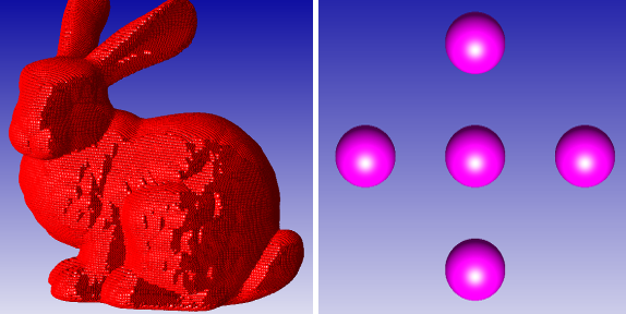
Demonstrating the effect of the 3D sphere vertex marker
Creating a Shell From Other Types of Geometry
HOOPS Visualize Desktop gives you the ability to transform other types of geometry into shells. For instance, you might want to transform a sphere into a shell in order to modify its points. Or you might want to convert a polygon into a shell in order to texture it. All that is needed is the key to the object you wish to translate.
    // convert a sphere to a shell
    HPS::ShellKey newSphereShell = mySegmentKey.InsertShellFromGeometry(sphereKey);

    // convert a cylinder to a shell
    HPS::ShellKey newCylinderShell = mySegmentKey.InsertShellFromGeometry(cylinderKey);

    // convert a text string to a shell
    HPS::ShellKey newTextShell = mySegmentKey.InsertShellFromGeometry(textKey);
// convert a sphere to a shell
HPS.ShellKey newSphereShell = mySegmentKey.InsertShellFromGeometry(sphereKey);

// convert a cylinder to a shell
HPS.ShellKey newCylinderShell = mySegmentKey.InsertShellFromGeometry(cylinderKey);

// convert a text string to a shell
HPS.ShellKey newTextShell = mySegmentKey.InsertShellFromGeometry(textKey);
You can also convert a NURBS surface, a mesh, or a polygon into a shell using the same method.
Limitations
When inserting a shell from text geometry, the text needs to be inserted directly into the window segment in order for this call to succeed.
Optimizing Shells
HOOPS Visualize Desktop is able to perform several computations to prepare shell data for improved rendering performance. Both HPS::ShellKey and HPS::ShellKit contain the Optimize method for this purpose. The process of shell optimization does incur an initial overhead cost, but can improve performance at render time. Five optimizations are currently available:
- tolerance controls the identification of duplicate points. If this specification is given in object space, then the points that are separated by a distance less than this value are considered equal. Often, one cannot ascertain a good value for an object-relative tolerance. In this case, specify the tolerance using
FeatureSizePercentage. Feature size is defined to be the smallest non-zero distance between any two adjacent vertices on any face. It is calculated internally by theOptimizemethod, and is constant for the entire collection of faces. The feature-relative tolerance is expressed as a percentage of this minimum distance. - normal tolerance controls the identification of duplicate points. Points which have an angular difference greater than the specified normal tolerance are assumed to be unique.
- orphan elimination culls vertices that are not referenced by any face.
- fix handedness is a convenience for converting a minority of faces to the handedness comprising the majority. It will reverse the winding of the minority faces. This option will also fix the special winding of holes (and nested holes) in a shell face.
- reverse handedness is a convenience for reversing the winding of shell faces if the option “fix handedness” gives you an inside-out shell.
The optimizations are set using a HPS::ShellOptimizationOptionsKit. For example:
    HPS::ShellOptimizationOptionsKit sook;
    sook.SetTolerance(0.1f, HPS::Shell::ToleranceUnits::FeatureSizePercentage);
    sook.SetHandednessOptimization(HPS::Shell::HandednessOptimization::Fix);

    myShellKey.Optimize(sook);
HPS.ShellOptimizationOptionsKit sook = new HPS.ShellOptimizationOptionsKit();
sook.SetTolerance(0.1f, HPS.Shell.ToleranceUnits.FeatureSizePercentage);
sook.SetHandednessOptimization(HPS.Shell.HandednessOptimization.Fix);

myShellKey.Optimize(sook);
Merging Shells
Sometimes it is convenient to take a group of shells and merge them into a single monolithic shell. Such an action will often result in increasing rendering performance or simplified application logic. HPS::SegmentKey::OptimizeWithMapping allows you to merge shells within a segment. The SegmentOptimizationOptionsKit::SetScope method controls searching the given segment, its children or includes. Optimization only considers merging the shells within each segment.
        HPS::SegmentOptimizationOptionsKit segmentOOK;
        segmentOOK.SetScope(SegmentOptimizationOptions::Scope::SegmentOnly);
        segmentOOK.SetShellMerging(true);

        OptimizeMappingResults omResults = mySegmentKey.OptimizeWithMapping(segmentOOK);
HPS.SegmentOptimizationOptionsKit segmentOOK = new HPS.SegmentOptimizationOptionsKit();
segmentOOK.SetScope(SegmentOptimizationOptions.Scope.SegmentOnly);
segmentOOK.SetShellMerging(true);

OptimizeMappingResults omResults = mySegmentKey.OptimizeWithMapping(segmentOOK);
As shown in the code snippet above, the HPS::OptimizeMappingResults object is returned from the optimization operation and will contain information related to the shells that were merged. That object can then be iterated, which provides the vertex, face, and edge data offsets in the output shell with respect to the input shells:
        OptimizeMappingResultsIterator it = omResults.GetIterator();

        while (it.IsValid()) {
            if (it.GetMergedShellInfo(out_shell_key, out_vertex_offset, out_face_offset, out_edge_offset)) {
                // do something with the merged shell data
            }

            it.Next();
        }
OptimizeMappingResultsIterator it = omResults.GetIterator();

while (it.IsValid())
{
    if (it.GetMergedShellInfo(out out_shell_key, out out_vertex_offset, out out_face_offset, out out_edge_offset))
    {
        // do something with the merged shell data
    }

    it.Next();
}
When any information you want is recovered, the original shells can be flushed with:
omResults.FlushMerged();
omResults.FlushMerged();
Computing Spatial Relationships Between Shells and Points
HOOPS Visualize Desktop offers the shell relation interface to detect relationships between two shells or between a shell and a set of points. Additionally, the interface can differentiate between points on the surface of a shell or those enclosed by a shell, and can compute the distance between the shell and a point set.
While performing these tests, you can optionally instantiate a HPS::TreeContext to improve performance. The tree context partitions world space to make collision tests faster. However, there is a resource overhead involved with building this object, so it usually only makes sense to use one when you are testing against a large number of shells and points. The tree context becomes invalid if you modify the tree in any way. See the next code snippet for an example of how to use it.
The collision test works on a HPS::ShellKey or a HPS::ShellKit.
Enclosure
When computing whether points are enclosed by a shell, it is assumed the shell you are testing against is geometrically closed. If the shell is not closed, the results are undefined. The enclosure test can determine whether a point is inside, outside, or on the surface of the shell.
The following code snippet assumes a shell has already created:
    // here are the points we are testing against
    PointArray pointArray(3);
    pointArray[0] = Point(0, 0, 0);
    pointArray[1] = Point(1, 0, 0);
    pointArray[2] = Point(0, 2, 0);

    // the ShellRelationOptionsKit is setup for an enclosure test
    HPS::ShellRelationOptionsKit srok;
    srok.SetTest(HPS::Shell::RelationTest::Enclosure);

    // specify an optional TreeContext
    HPS::TreeContext treeContext;
    srok.SetTreeContext(treeContext);

    // the ShellRelationResultsKit will contain the results of the computation
    HPS::ShellRelationResultsKit srrk;

    // this line performs the actual test
    myShellKey.ComputeRelation(pointArray, srok, srrk);

    // we sent in 3 points, so our result set will have 3 results
    HPS::ShellRelationArray shellRelationArray;
    srrk.ShowRelations(shellRelationArray);

    // iterate over each result
    for (size_t i = 0; i < shellRelationArray.size(); i++) {
        HPS::Shell::Relation relation = shellRelationArray[i];

        if (relation == HPS::Shell::Relation::In) {
            // this point is inside the shell
        }
        else if (relation == HPS::Shell::Relation::Out) {
            // this point is outside the shell
        }
        else if (relation == HPS::Shell::Relation::On) {
            // this point is on the surface of the shell
        }
    }
// here are the points we are testing against
HPS.Point[] pointArray = new HPS.Point[3];
pointArray[0] = new HPS.Point(0, 0, 0);
pointArray[1] = new HPS.Point(1, 0, 0);
pointArray[2] = new HPS.Point(0, 2, 0);

// the ShellRelationOptionsKit is setup for an enclosure test
HPS.ShellRelationOptionsKit srok = new HPS.ShellRelationOptionsKit();
srok.SetTest(HPS.Shell.RelationTest.Enclosure);

// specify an optional TreeContext
HPS.TreeContext treeContext = new HPS.TreeContext();
srok.SetTreeContext(treeContext);

// the ShellRelationResultsKit will contain the results of the computation
HPS.ShellRelationResultsKit srrk = new HPS.ShellRelationResultsKit();

// this line performs the actual test
myShellKey.ComputeRelation(pointArray, srok, out srrk);

// we sent in 3 points, so our result set will have 3 results
float[] floatArray = new float[3];

HPS.Shell.Relation[] shellRelationArray = new HPS.Shell.Relation[3];
srrk.ShowRelations(out shellRelationArray);

// iterate over each result
for (int i = 0; i < shellRelationArray.size(); i++)
{
	HPS.Shell.Relation relation = shellRelationArray[i];

	if (relation == HPS.Shell.Relation.In)
	{
		// this point is inside the shell
	}
	else if (relation == HPS.Shell.Relation.Out)
	{
		// this point is outside the shell
	}
	else if (relation == HPS.Shell.Relation.On)
	{
		// this point is on the surface of the shell
	}
}
Distance
The distance test is the most computationally intensive test. It will return the closest distance to the shell for each point you specify. Using the previous code snippet as a framework, we can use this code to test for distance:
    // the ShellRelationOptionsKit is setup for a distance test
    srok.SetTest(HPS::Shell::RelationTest::Distance);

    // perform the test
    myShellKey.ComputeRelation(pointArray, srok, srrk);

    // get results
    FloatArray distanceArray;
    srrk.ShowDistances(distanceArray);

    // iterate over each result
    for (size_t i = 0; i < distanceArray.size(); i++) {
        // get distance for each point
        float distance = distanceArray[i];
    }
// the ShellRelationOptionsKit is setup for a distance test
srok.SetTest(HPS.Shell.RelationTest.Distance);

// perform the test
myShellKey.ComputeRelation(pointArray, srok, out srrk);

// get results
srrk.ShowDistances(out floatArray);

// iterate over each result
for (int i = 0; i < floatArray.size(); i++)
{
	// get distance for each point
	float distance = floatArray[i];
}
Simple
The simple relation test is the least computationally intensive test. However, it can only determine whether or not a point is on the surface of the shell or not:
    // the ShellRelationOptionsKit is setup for a surface test
    srok.SetTest(HPS::Shell::RelationTest::Simple);

    // perform the test
    myShellKey.ComputeRelation(pointArray, srok, srrk);

    srrk.ShowRelations(shellRelationArray);

    // iterate over each result
    for (size_t i = 0; i < shellRelationArray.size(); i++) {
        HPS::Shell::Relation relation = shellRelationArray[i];

        if (relation == HPS::Shell::Relation::On) {
            // this point is on the surface of the shell
        }
        else if (relation == HPS::Shell::Relation::Off) {
            // this point is not on the surface of the shell
        }
    }
// the ShellRelationOptionsKit is setup for a surface test
srok.SetTest(HPS.Shell.RelationTest.Simple);

// perform the test
myShellKey.ComputeRelation(pointArray, srok, out srrk);

srrk.ShowRelations(out shellRelationArray);

// iterate over each result
for (int i = 0; i < shellRelationArray.size(); i++)
{
	HPS.Shell.Relation relation = shellRelationArray[i];

	if (relation == HPS.Shell.Relation.On)
	{
		// this point is on the surface of the shell
	}
	else if (relation == HPS.Shell.Relation.Off)
	{
		// this point is not on the surface of the shell
	}
}

