
3D Annotations
“3D” refers to 3D annotations. A 3D annotation is a subwindow in the PDF document which displays a 3D model.
3D > Add 3D
The “Add 3D” function allows 3D CAD data to be converted and inserted into a PDF Document. The 3D data will be imported as an annotation in its own subwindow.
Adding 3D is done in the following way:
Within the Tetra4D Enrich toolbar, choose 3D > Add 3D.
Define the position and the size of the 3D annotation by dragging a rectangle.
Select the 3D source file containing the model you want to load in the “Open File” dialog.
Define the conversion settings in the “3D Conversion Settings” dialog.
Press the OK button to confirm.
Remark:
3D models are read by Tetra4D Converter, which is part of the Tetra4D Enrich product. For more information about the 3D conversion settings, please refer to the Tetra4D Converter user manual.
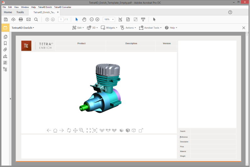
3D annotation in the PDF document
3D > Add 3D attributes
The Add 3D attributes function allows you to import attributes (meta-data) from an external source, such as for example a PDM (Product Data Management), a PLM (Product Lifecycle Management), or an ERP (Enterprise Resource Planning) application.
Tetra4D Enrich will correlate these attributes with the 3D parts that are currently in the PDF document. They can then be accessed in a Table or displayed in text fields by defining Actions, just like the attributes that have been read from the native CAD data.
Aside the import of meta-data, the Add 3D attributes allows you to:
Set unselectable parts,
Assign links to the imported meta-data.
Note
The attributes are imported from XML files. The mapping between the attributes and the 3D parts must be defined in the XML file because it is performed at the time of import. See below the definition of the XML format and the mapping methods.
Within the Tetra4D Enrich toolbar, choose 3D > Add 3D attributes.
Select the XML file containing the attributes you want to import in the “XML File” dialog.
Check the result of the import in the dialog that pops-up.
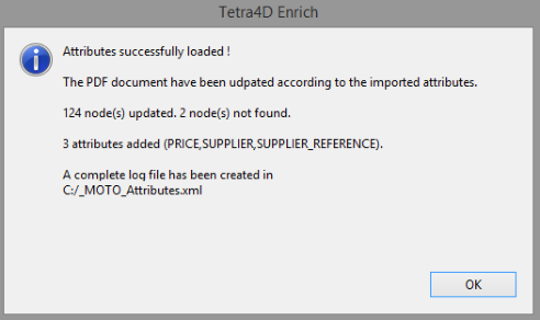
Dialog showing the result of the import of attributes operation
Note: the dialog presents several pieces of information:
Number of nodes (parts) to which attributes have been added.
Number of nodes (parts) that haven’t been found (mapping wasn’t possible).
Names of the attributes that have been added.
A Log file is generated in the folder where the XML file was read. It provides the user with a detailed list of updated nodes, according to the mapping key and value, and a list of nodes that haven’t been found.
Note
Imported attributes are added to the parts, but can’t be accessed in the document data tree like the attributes that have been read from the native CAD data. Imported attributes can only be accessed using the Table or the Actions features of Tetra4D Enrich.
Format of the XML file
The XML file must contain all the required information to define new attributes and to add these attributes to the 3D data that is in the 3D annotation. The XML file must be encoded in UTF8.
There are two different mapping methods:
Based on the value of an attribute of the part.
Based on the name of the part in the 3D annotation.
XML format, with a mapping based on the value of an attribute
Example of a file:
<attributes>
 <ATTRIBUTE key="AttribName" attribute_value="AttribValuePart1">
   <NEW_ATTRIB name="NewAttribName1" value="NewAttribName_Val1_Part1" />
   <NEW_ATTRIB name="NewAttribName2" value="NewAttribName_Val2_Part1" />
 </ATTRIBUTE>
 <ATTRIBUTE key="AttribName" attribute_value="AttribValuePart2">
   <NEW_ATTRIB name="NewAttribName1" value="NewAttribName_Val1_Part2" />
   <NEW_ATTRIB name="NewAttribName2" value="NewAttribName_Val2_Part2" />
 </ATTRIBUTE>
</attributes>
Key for the mapping:
<ATTRIBUTE key="AttribName" attribute_value="AttribValuePart1">
AttribName: Must be an existing attribute in the CAD file
AttribValuePart1: Value of the attribute of the part
New attribute definition:
<NEW_ATTRIB name="NewAttribName1" value="NewAttribName_Val1_Part1" />
NewAttribName1: Name of the new attribute
NewAttribName_Val1_Part1: Value of the new attribute for the part
Example:
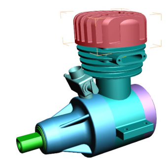
CAD model in the PDF document showing Native CAD attributes for the 2 selected parts
|
|
|---|---|
|
|
Imported XML file to add attributes
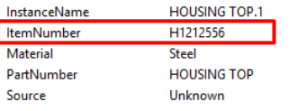
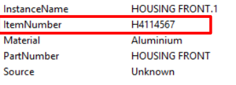
<attributes>
   <ATTRIBUTE key="ItemNumber" attribute_value="H1212556">
      <NEW_ATTRIB name="SUPPLIER" value="Supplier A" />
      <NEW_ATTRIB name="SUPPLIER_REFERENCE" value="RefA01" />
   </ATTRIBUTE>
   <ATTRIBUTE key="ItemNumber" attribute_value="H4114567">
      <NEW_ATTRIB name="SUPPLIER" value="Supplier B" />
      <NEW_ATTRIB name="SUPPLIER_REFERENCE" value="RefB01" />
   </ATTRIBUTE>
</attributes>
mapping is performed using the ItemNumber attribute
2 attributes are added to the 3D parts: SUPPLIER and SUPPLIER_REFERENCE
XML format, with a mapping based on name of the part in the 3D annotation
Example of a file:
<attributes>
   <NAME key="PartName1">
      <NEW_ATTRIB name="NewAttribName1" value="NewAttribName_Val1_Part1"/>
      <NEW_ATTRIB name="NewAttribName2" value="NewAttribName_Val2_Part1"/>
   </NAME>
   <NAME key="PartName2">
      <NEW_ATTRIB name="NewAttribName1" value="NewAttribName_Val1_Part2"/>
      <NEW_ATTRIB name="NewAttribName2" value="NewAttribName_Val2_Part2"/>
   </NAME>
</attributes>
Key for the mapping:
<NAME key="PartName1">
PartName1: Name of the part as shown in the data tree
New attribute definition:
<NEW_ATTRIB name="NewAttribName1" value="NewAttribName_Val1_Part1"/>
NewAttribName1: Name of the new attribute
NewAttribName_Val1_Part1: Value of the new attribute for the part
Example:
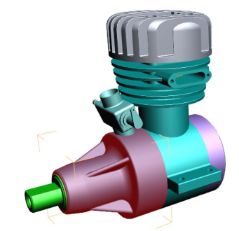
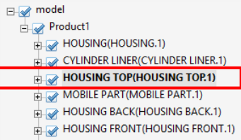
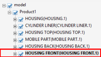
CAD model in the PDF document showing Name of the parts in the data tree

|

|
|---|---|
|
|
Imported XML file to add attributes
<attributes>
   <NAME key="HOUSING TOP(HOUSING TOP.1)">
      <NEW_ATTRIB name="SUPPLIER" value="Supplier A"/>
      <NEW_ATTRIB name="SUPPLIER_REFERENCE" value="RefA01"/>
   </NAME>
   <NAME key="HOUSING FRONT(HOUSING FRONT.1)">
      <NEW_ATTRIB name="SUPPLIER" value="Supplier B"/>
      <NEW_ATTRIB name="SUPPLIER_REFERENCE" value="RefB01"/>
   </NAME>
</attributes>
Mapping is performed using names of the parts (as shown in the data tree)
2 attributes are added to the 3D parts: SUPPLIER and SUPPLIER_REFERENCE
Setting unselectable parts (in the 3D annotation)
The Add 3D attributes function allows you to also define some behavior settings linked to the parts. It is possible to disable the selection of parts in the 3D annotation by adding a specific attribute and its value to the parts that must be set as unselectable.
The parts that are set as “unselectable” won’t be selectable in the 3D annotation, but will remain selectable in a table (if table is linked to the 3D annotation).
As a default, all the parts are selectable.
Attribute name: IsSelectable
Value: False
Example
<attributes>
   <NAME key="PartName1">
      <NEW_ATTRIB name="NewAttribName1" value="NewAttribName_Val1_Part1"/>
      <NEW_ATTRIB name="NewAttribName2" value="NewAttribName_Val2_Part1"/>
      <NEW_ATTRIB name="IsSelectable" value="False" />
   </NAME>
</attributes>
Assigning links to imported meta-data
The Add 3D attributes function allows you to assign a link (or several links) to an imported meta- data. The supported types of links are:
Attachment: Opens a document that is attached in the current PDF document
Web URL: Opens a Web URL in a Web browser
These links can be accessed when the meta-data is displayed in a text field by an action “Set text in field”, triggered by an “On 3D part” event.
Note
It is possible to define one attachment and/or one URL only..
Example of a file (partial):
<ATTRIBUTE key="ItemNumber" attribute_value="H7894561">
   <NEW_ATTRIB name="SUPPLIER" value="Tetra4D" attachment="Housing.pdf" hyperlink="www.tetra4d.com"/>
</ATTRIBUTE>
Definition of links:
attachment="Housing.pdf" hyperlink="www.tetra4d.com"attachment: key to define an attached document (Housing.pdf”) hyperlink: key to define a URL (www.tetra4d.com)
Result:
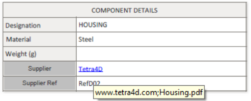
When the HOUSING part is selected, the SUPPLIER meta-data is shown in the “Supplier field” (value is Tetra4D)
The SUPPLIER value is automatically displayed has having a link, and a tooltip shows what the links are
User can click in the text field to open the links.
3D > Replace 3D
This function enables you to replace an existing 3D annotation in a PDF document with a new set of 3D CAD data. If this PDF document contains a Carousel of views and a Table, these two items will be updated accordingly to the new 3D CAD data. If the document contains actions, the “generic” actions will also be updated.
Note
Generic actions are those that can be retained with the new 3D model because they are not linked to something particular in the original 3D data, or because the nature of the action is also applicable for any 3D model. For example, the activation of the next view, the activation of the Solid rendering mode would be generic actions. Conversely, an action linked to a button that would change the color of a particular part of the 3D model is not a generic one.
Furthermore, the replace 3D feature does not support the “Add 3D Attributes” function. If you need to add external attributes (that are “connected” to the 3D model), you must first execute the replace the 3D feature to update the PDF document (3D annotation, table, Carousel of views, generic actions), and then import the 3D attributes using the Add 3D attributes function.
In such a case, it could be required to edit the table after using the Add 3D attributes function in order to fill some existing columns with the newly imported attributes.
- Within the Tetra4D Enrich toolbar, choose 3D > Replace 3D.Note: If the active page of the 3D PDF document contains several 3D annotations, make sure first to activate the 3D annotation that will be replaced (the Replace 3D feature automatically selects the active 3D annotation).
|To activate a 3D annotation, just place the mouse cursor inside it and make a change in the viewing orientation for example.
Select the 3D source file containing the model you want to load in the “Open File” dialog.
Define the conversion settings in the “3D Conversion Settings” dialog.
Press the OK button to confirm.
Remark:
3D models are read by Tetra4D Converter, which is part of Tetra4D Enrich product. For more information about the 3D Conversion settings, please refer to the Tetra4D Converter user manual.
Example:
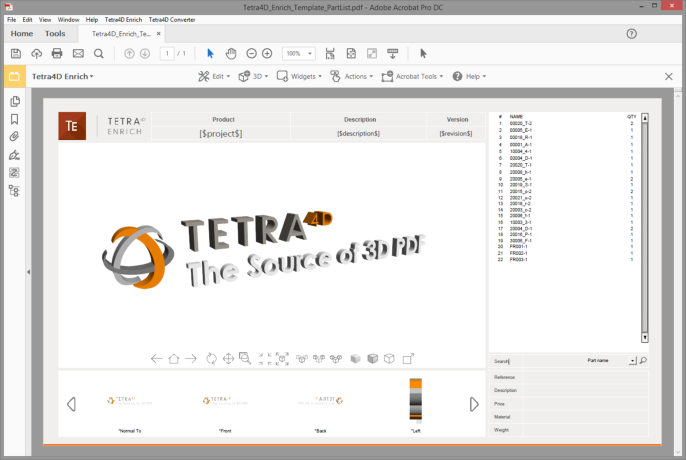
Template document created using Tetra4D Enrich
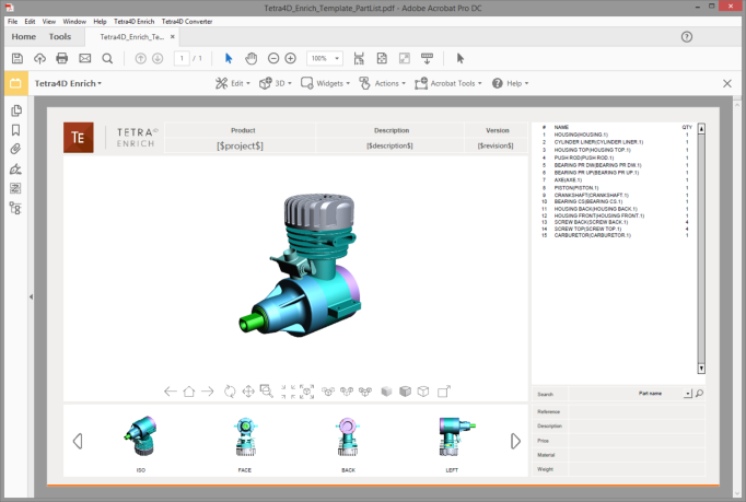
Populated template with new 3D CAD data (after Replace 3D operation)