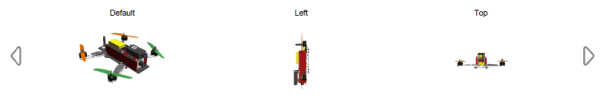
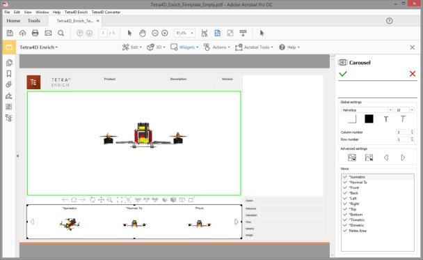
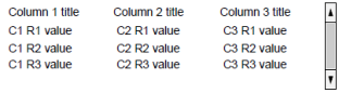
The carousel of views is a widget that can be inserted in the PDF document to list the 3D views. The
views are presented as image thumbnails, allowing the user to easily browse and activate one. To
activate a view, click on its thumbnail. The 3D annotation will then transition to that view.
The carousel can be defined either as a horizontal or vertical frame. By default, the
carousel shows three views and two buttons that allow the user to scroll the views. The
buttons will be automatically repositioned depending on the orientation of the carousel.
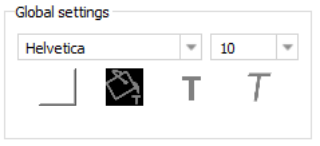
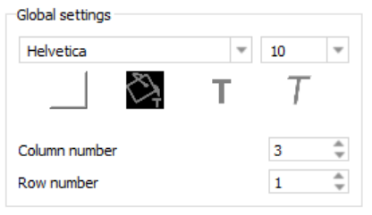
Font settings: Defines the font and the font size for the names of views displayed in the thumbnails.
Font color, Bold, Italic: Applies to the names of views displayed in the thumbnails.
Background color: Defines the background color of the carousel.
Note
The background color applies to the carousel only and doesn’t affect the
thumbnails themselves.
Column number: Defines the number of columns of the carousel. The value is limited to a range of 1 to 10
Row number: Defines the number of rows of the carousel. The value is limited to a range of 1 to 10.
Note
Of particular importance are the “Column number” and “Row number” options. Make sure
the number of rows and columns makes sense for the space that the carousel is occupying.
For example, you normally wouldn’t want a horizontally oriented carousel to have a single column with multiple rows.
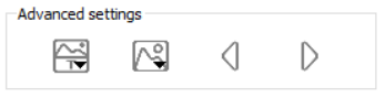
Advanced settings area of the Carousel edit panel
Display/hide poster/text and change text position:
Display text: Displays or hides the view titles in the carousel
Display poster: Displays or hides the screenshot (poster) images in the carousel
Change text position: Repositions the view titles. The options are above or below the poster images.
Change or reload posters:
Change poster: Opens a dialog which allows to select a new poster image from the file system.
This option applies to the thumbnail currently selected in the Carousel.
Update poster: Regenerates the view poster image. This action may be required if the
view has been modified by the user and the poster needs to be updated to reflect the
modification.
This option applies to the thumbnail currently selected in the Carousel.
Update all posters: Regenerates all view poster images. This action may be required if some views have been modified by the user and the posters need to be updated to reflect the modifications.
Change the previous / next button icon:
The left and right arrows icons that appear in the carousel of views can be changed by selecting a new image from the file system.
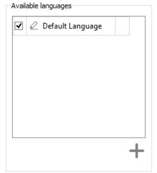
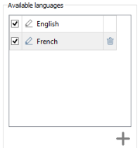
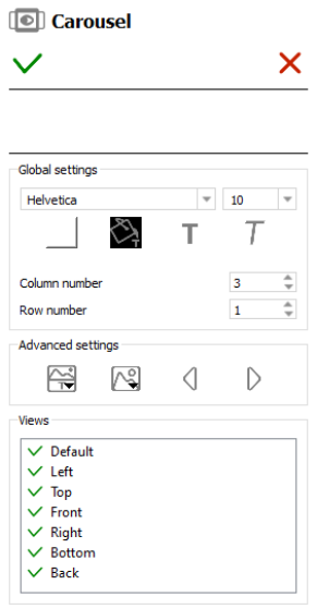
If you wish to exclude certain views from the view carousel, simply uncheck the view name in the
“Views” area of the sidebar. The green check will be replaced with a red X indicating the view is to be
excluded.
Views can also be reordered. Click on one view in the list and drag it to another place. Reordering the
views only affects the carousel presentation - it has no effect on the PDF views.
Deactivation of a view: Click on an active view (marked by a green check) in the list.
Activation of a view: Click on a deactivated view (marked by a red cross) in the list.
Reordering views: Click the view to be reordered while maintaining the mouse button pressed, and drag the view to the new position in the list. Make sure the view is not deactivated.
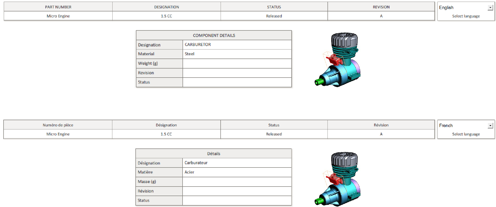
The “Add part list (flat)” menu allows you to create a table in the PDF document. The flat part list is
generated by parsing the model structure of the 3D parts.
This table is generated from the 3D data in the PDF document.
Within the Tetra4D Enrich toolbar, choose Widget > Add part list (flat).
Drag a rectangle to define the location and the size of the table.
Use the frame controllers to resize the table.
Drag the table border to reposition the table if required.
Adjust the table properties to your specifications by selecting the options in the Edit panel in the right.
Note
Refer to Definition of the part list and table settings to have detailed explanations about how to customize the table presentation.
Click on the green check “Validate the table modifications” icon to save the carousel, or
Click on the red “X” “Cancel the table modifications” icon to discard the changes.
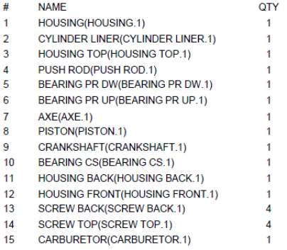
The flat part lists are generated according to the 3D model currently present in the PDF
document.
The flat part list only lists the components of the assembly and the total number of these
components, independent of their position in the assembly hierarchy.
The “Add part list (hierarchical)” menu allows you to create a table in the PDF document. The
hierarchical part list is generated by parsing the model structure of the 3D parts.
This table is generated from the 3D data in the PDF document.
Within the Tetra4D Enrich toolbar, choose Widget > Add part list (hierarchical).
Drag a rectangle to define the location and the size of the table.
Use the frame controllers to resize the table.
Drag the table border to reposition the table if required.
Adjust the table properties to your specifications by selecting the options in the Edit panel in the right.
Note
Refer to Definition of the part list and table settings to have detailed explanations about how to customize the table presentation.
Click on the green check “Validate the table modifications” icon to save the table, or
Click on the red “X” “Cancel the table modifications” icon to discard the changes.
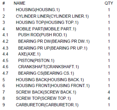
The hierarchical part lists are generated according to the 3D model currently present in
the PDF document.
The hierarchical part list reflects the hierarchy of the 3D information. Sub-assemblies are
shown with indented part names and the components quantities are calculated locally, at
the hierarchical level where they are found.
Within the Tetra4D Enrich toolbar, choose Widget > Add table from CSV.
Drag a rectangle to define the location and the size of the table.
Use the frame controllers to resize the table if required.
Drag the table border to reposition the table if required.
Adjust the table properties to your specifications by selecting the options in the Edit panel in the right.
Note
Refer to Definition of the part list and table settings to have detailed explanations about how to customize the table presentation.
Click on the green check “Validate the table modifications” icon to save the carousel, or
Click on the red “X” “Cancel the table modifications” icon to discard the changes.
Table created from a CSV file has no link with the 3D parts of the 3D annotation.
To map table rows with 3D parts, refer to “3D Attributes / 3D Mapping” section.
To create actions triggered by a selection of a row of the table, refer to “On table row”
section.
Note
CSV format
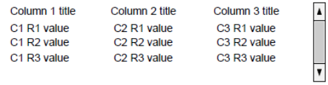
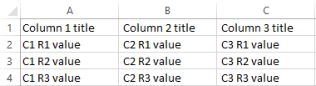
The CSV format expected by Tetra4D Enrich is shown below:
Column 1 title;Column 2 title;Column 3 title
C1 R1 value;C2 R1 value;C3 R1 value
C1 R2 value;C2 R2 value;C3 R2 value
C1 R3 value;C2 R3 value;C3 R3 value
The first line of the CSV file will be used to define the title of the columns in the table.
The separator must be “;”.
A table can be defined using data that is stored on the system clipboard. This is very similar to adding
the table from a CSV file – the only difference is that instead of showing a dialog to select a CSV file,
Tetra4 Enrich will grab the data automatically from the clipboard.
Make sure the clipboard contains the table information. Then, within the Tetra4D Enrich toolbar, choose Widget > Add table from clipboard.
Drag a rectangle to define the location and the size of the table.
Use the frame controllers to resize the table.
Drag the table border to reposition the table if required.
Adjust the table properties to your specifications by selecting the options in the Edit panel in the right.
Note
Refer to Definition of the part list and table settings to have detailed explanations about how to customize the table presentation.
Click on the green check “Validate the table modifications” icon to save the table, or
Click on the red “X” “Cancel the table modifications” icon to discard the changes.
Tables created from the clipboard have no link with the 3D parts of the 3D annotation. To
map table rows with 3D parts, refer to “3D Attributes / 3D Mapping”.
To create actions triggered by a selection of a row of the table, refer to “On table row”
section.
Note
Format of information copied in the clipboard
The contents of the clipboard must correspond to a table having multiple lines and rows.
The column titles must be defined by the first row.
Supported applications to copy the table information in the clipboard are Microsoft Excel
and Google Sheets.
Information in a spreadsheet (before being copied in the clipboard)
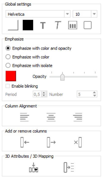
The Emphasize feature allows you to control how parts corresponding to the selected row in the
table are emphasized in the 3D annotation.
There are three possibilities:
Emphasize with color and opacity: Parts are emphasized by a color change while all the other parts are displayed with opacity.
Emphasize with color: Parts are emphasized by a color change while all the other parts remain displayed without any change.
Emphasize with isolate: Parts are emphasized by an “isolate” operation (they remain visible and all the other parts are hidden). A “fit-all” operation is automatically performed in order
to zoom to the emphasized parts
Depending on the chosen emphasize mode, some additional settings are available:
Emphasize color: Defines the color used to emphasize the search results.
Opacity slider: Defines the opacity value, when the “Emphasize with color and opacity” mode is selected.
Enable blinking: Activates blinking of the search results.
Blinking is defined by two parameters:
* Period: Defines the period time (in seconds) for every blink of the parts.
* Number: Defines the number of blinking that occur for any highlight event.
Note: The “Enable blinking” option is not available with the “Emphasize by isolate” mode.
The 3D Attributes feature allows you to control which data is displayed in the columns of the table.
In case of a Part list (flat or hierarchical), the following information is listed in the table by default:
row number (title of column: #, name in the list of attributes: #Computed #),
part name (title of column: NAME, name in the list of attributes: #Computed NAME),
quantity (title of column: QTY, name in the list of attributes: #Computed QTY).
However, it is possible to display different information in one existing column, or in an added
column.
The 3D Mapping feature allows you to map the information currently displayed in the table with the
3D model. This feature is meant to be used with tables created using the features Add table from
CSV or Add table from clipboard.
3D Attributes / 3D Mapping Settings area of the Table edit panel
Fill column with attribute: Fill the selected column with attributes linked to the 3D model.
Select the column you want to fill by selecting a cell in the column. There is no need to select the full column, just the top row of the column.
Click on the Fill column with attributes icon.
Select the attribute in the list of attributes from the dropdown.
Check the result in the table.
The attributes that are listed in the list depend on the CAD model currently loaded in the
PDF document, and on the additional attributes that may have been imported in the PDF
document using the “ADD 3D attribute” feature.
The default information that is listed in the table consists of:
Row number (title of column: #, name in the list of attributes: #Computed #),
Part name (title of column: NAME, name in the list of attributes: #Computed NAME),
Quantity (title of column: QTY, name in the list of attributes: #Computed QTY).
List of attributes provided by the Fill column with attribute feature
: System information (default information displayed when the table is created).
: Attributes that have been imported and linked to the 3D parts.
: (no icon) Attribute defined in the CAD data (so that have been read while adding the 3D information in the PDF document.
Map selected column with 3D parts: Use the selected column to map the rows of the table with the 3D parts.
Create the table using “Add table from CSV” or “Add table from clipboard” features.
Note: See detailed explanations on “Add table from CSV” or “Add table from clipboard”.
Select the column you want to use as a key for the mapping by selecting a cell in the column. Note: An example is provided next page.
Click on the Map selected column with 3D parts icon.
Check the result of the mapping in the dialog that pops-up.
Click OK to close the dialog.
The “Map selected column with 3D parts” feature is available with tables created using
the “Add table from CSV” or “Add table from clipboard” features.
In the case of a table created using the Part list (flat or hierarchical) feature, this function
will not be active, because these tables are already linked with the 3D data.
Mapping the rows of the table with 3D parts enables a cross-highlight between the table
and the 3D annotation, when selecting a row in the table or when selecting a part in the
3D annotation.
The “mapping” means “correlate the values from this column to the corresponding 3D
part”. The column title is important, because it is the key used to perform the mapping.
For example, if the column title is “ItemNumber”, the mapping will work if the 3D parts
contain an attribute named “ItemNumber”.
Enrich will look for all the parts, and make the mapping between the table row and a
particular part that matches ItemNumber.
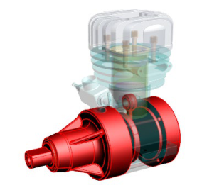
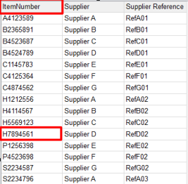
Remark: Example of mapping between a CSV table and the 3D parts
The table below is mapped with the 3D parts based on the column ItemNumber (in this
example, ItemNumber is an attribute which is defined in all the 3D parts).
Once the table has been inserted in the document, the ItemNumber column must be
selected and the feature “Map selected column with 3D parts” will execute the mapping
based on this key.
Afterwards, the mapping is managed by looking at all the values listed in the column of
parts attributes. The table row and part become linked when the value of the key
attribute for a 3D part matches with the value of the attribute present in the table.
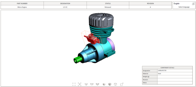
Below, the main housing part is linked to the highlighted table row because the
ItemNumber values are the same: H7894561.
Mapping of the table rows with the 3D parts based on an attribute:
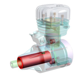
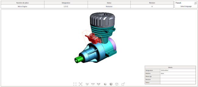
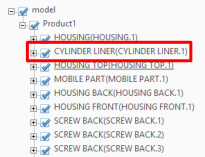
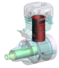
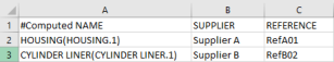
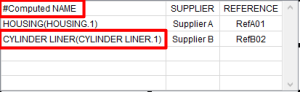
The table below is mapped with the 3D parts based on the names of the parts.
The names of the parts can be accessed using the key #Computed NAME.
Consequently, the title of the column that contains the names of the parts must be
#Computed NAME.
Mapping of the table rows with the 3D parts based on the names of the parts:
The Emphasize feature allows you to control how the results of the search are emphasized in the 3D
annotation.
There are three possibilities:
Emphasize with color and opacity: The search results are emphasized by a color change while all the other parts are displayed with opacity.
Emphasize with color: The search results are emphasized by a color change while all the other parts remain displayed without any change.
Emphasize with isolate: The search results are emphasized by an “isolate” operation (they remain visible and all the other parts are hidden). A “fit-all” operation is automatically performed in order to zoom to the emphasized parts
Depending on the chosen emphasize mode, some additional settings are available:
Emphasize color: Defines the color used to emphasize the search results.
Opacity slider: Defines the opacity value, when the “Emphasize with transparency” mode is selected.
Enable blinking: Activates blinking of the search results.
Blinking is defined by two parameters:
Period: Defines the period time (in seconds) for every blink of the parts.
Number: Defines the number of blinking that occur for any highlight event.
Note: The “Enable blinking” option is not available with the “Emphasize by isolate” mode.
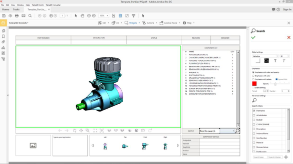
what search options will be accessible in the Search widget,
search presets.
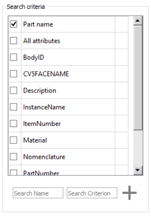
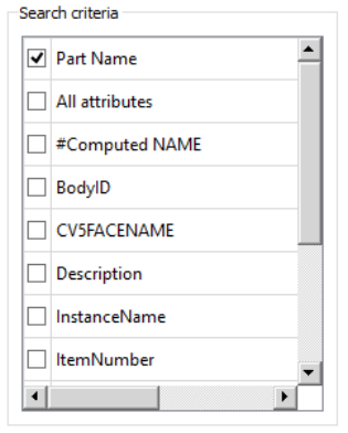
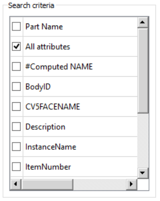
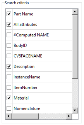
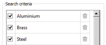
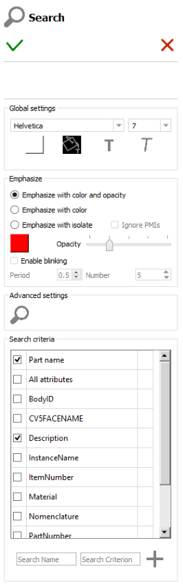
Search criteria settings area of the Search edit panel
Note
When the Search widget is created in the PDF document, the author must define what
search criteria and search presets if any will be proposed to the consumer of the PDF
document.
It is for example possible to limit the search operation to the names of the parts, or to
one or a few attributes. Conversely, the search can be performed on all the attributes
linked to the parts from the 3D annotation.
There are several search criteria possibilities:
Part name: The search will be performed on the names of the parts.
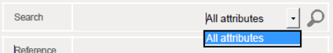
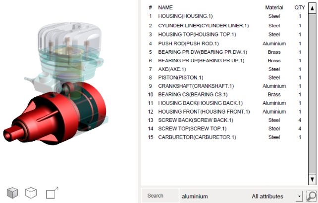
All attributes: The search will be performed on all the attributes that are linked to the parts from the 3D annotation.
Attribute: The search will be performed on the selected attributes only.
Note
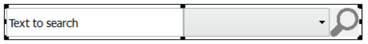
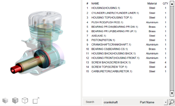
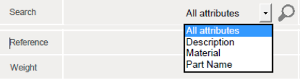
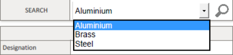
The Search widget is composed by three different parts:
A field where user will enter the search string
A dropdown list in which the search criteria is selected
A button with Search icon that execute the search operation
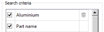
In addition to these search criteria, Search presets can be defined.
The Search presets enable to execute Search operations with predefined search criteria (Attribute
and value).
Note: Refer to Search Presets sample to have detailed explanations about the creation
of presets.
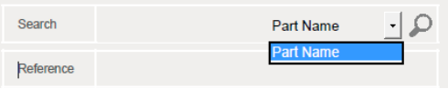
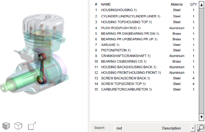
Example of Search operations performed with different criteria
The Search criteria feature allows you to define what search options will be accessible in the Search
widget.
Your multilingual generative AI assistant for documentation. Ask me anything about Tetra4D Enrich in your own language, or choose a sample question below to start a conversation:
What is Tetra4D Enrich?
What are the latest release notes for Tetra4D Enrich?
How do I start evaluating Tetra4D Enrich?
How can I get assistance?
FOURDY may store conversations according to OpenAI's policy. Responses may not always be accurate.

 Display/hide poster/text and change text position:
 Change or reload posters:
 Change the previous / next button icon:
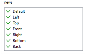
 Background color: Defines the background color of the table.
 Make header bold: set the header of the table to bold
 Add a border: Draws a frame around the table.
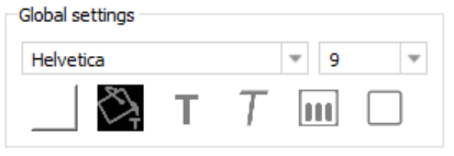
 Emphasize color: Defines the color used to emphasize the search results.
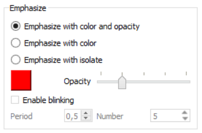
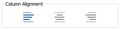
 Align left: Align the selected column to left.
 Align Center: Align the selected column to center.
 Align right: Align the selected column to right.
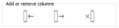
 Insert column to the left: Insert a new column to the left of the selected one.
 Insert column to the right: Insert a new column to the right of the selected one.
 Delete column: Delete the selected column.
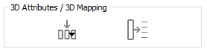
 Fill column with attribute: Fill the selected column with attributes linked to the 3D model.
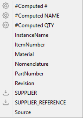
 : System information (default information displayed when the table is created).
 : Attributes that have been imported and linked to the 3D parts.
 : (no icon) Attribute defined in the CAD data (so that have been read while adding the 3D information in the PDF document.
 Map selected column with 3D parts: Use the selected column to map the rows of the table with the 3D parts.
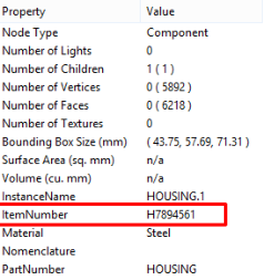

 Background color: Defines the background color of the Search widget.
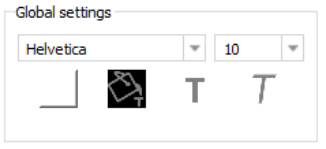
 Emphasize color: Defines the color used to emphasize the search results.
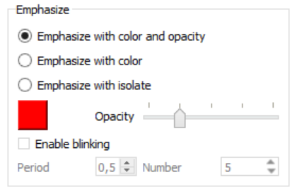
 Change the search button icon: