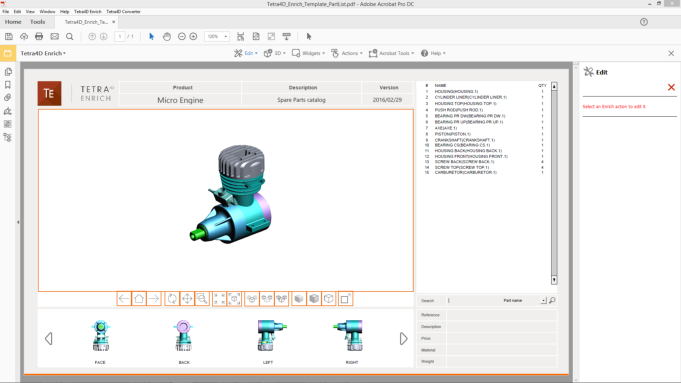
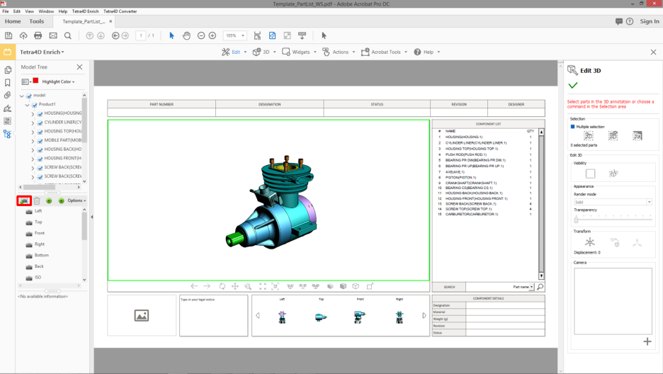
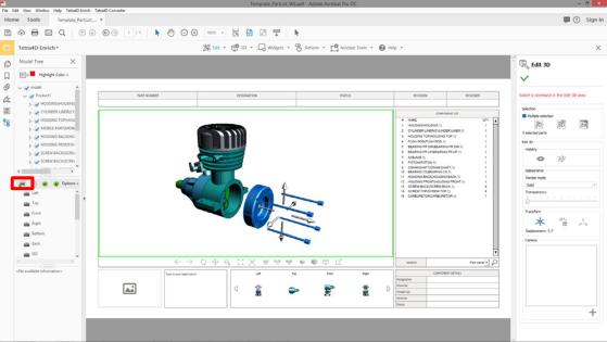
This section shows a detailed explanation about the possible modifications of the 3D annotation.
Within the Tetra4D Enrich toolbar, choose Edit 3D.
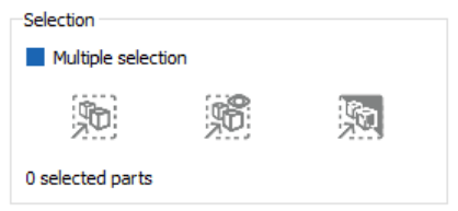
In the Edit 3D panel, check the “Multiple selection” mark to toggle the parts selection mode between the standard Adobe Acrobat one and the Tetra4D Enrich “multiple selection” mode.
Note: Refer to “Edit 3D: Selection modes” to have detailed explanations about the selection feature provided by Edit 3D.
Use the selection features to control or modify the current selection.
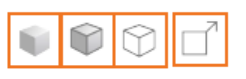
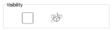
Change the visibility of parts with the Visibility check mark and with the Invert visible parts icon.
Note: Refer to “Edit 3D: Control of part visibility” to have detailed explanations about the visibility status check behavior and the Invert visible parts feature.
Change the rendering mode or the selected parts with the Render mode drop-down list, and change the transparency settings of the selected parts using the Transparency slider.
Note: Refer to “Edit 3D: Modification of parts appearances ” to have detailed explanations about the Appearances feature.
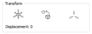
Click the icon “Activate transform mode” to enable the transform feature, and use the handler to move the selected parts.
Note: Refer to “Edit 3D: Transform feature” to have detailed explanations about the transform feature.
Click the save Camera view icon to create a local camera and activate any existing camera using the list of cameras.
Note: Refer to “Edit 3D: Camera feature” to have detailed explanations about the Camera feature.
Click on the green check to accept the modification and close the function.
The Edit 3D feature provides the ability to select several parts at the same time to ease and shorten
the process of creating views when the visibility and/or the positions of parts must be changed.
Note
The selection mode of Adobe Acrobat makes it possible to select a single part or a group
of parts if they all belong to the same hierarchical level of an assembly, but doesn’t
provide the ability to select simultaneously any parts from one assembly.
Check the Multiple selection mark to enable the multiple selection mode
Select in the 3D annotation the part to be added to the selection
Note: The selected parts are highlighted in blue.
Add a part to the selection set by selecting it in the 3D annotation
Note: It is not required to press the CTRL Key to add a part to the selection.
Click again an already selected part to unselect it
Select one the available feature (Visibility status or Transform), or
Note: See below for details about selection features.
Select one the Selection option to modify the selection set, or
Click into the 3D annotation to unselect all the parts
Note
When working with the Edit 3D feature, it is recommended not to select parts in the data
tree because the multiple selection mechanism is designed for 3D selection of parts, and
because it overrides the Adobe Acrobat standard selection feature (even when the
multiple selection is not active).
Note
It is possible to switch between the standard Adobe Acrobat selection mode and the
multiple selection mode during one selection sequence.
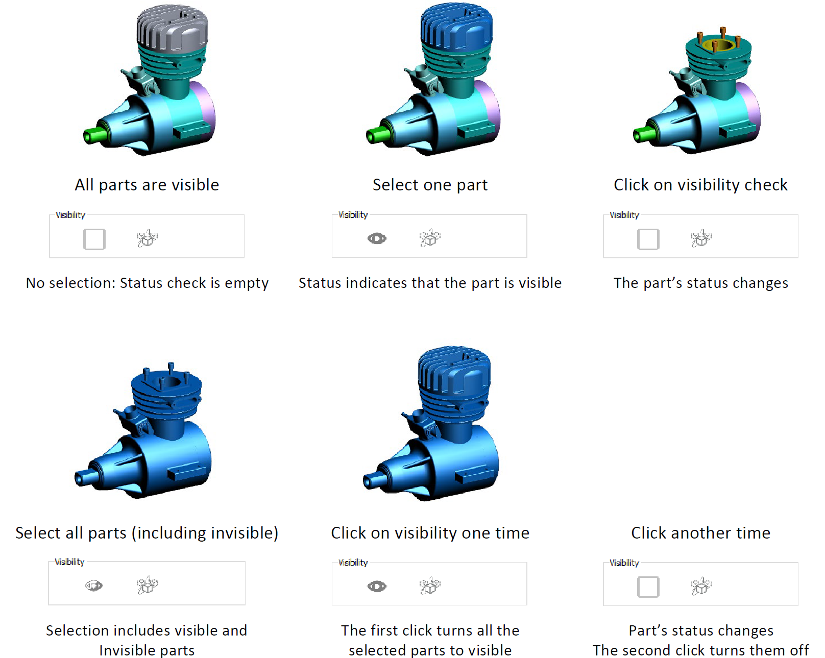
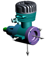
The Visibility check mark provides a status about the visibility of the selected parts, and makes it
possible to change this status. The Invert visible parts feature toggles the visibility status of all the
parts. It is meant to be used in combination with the selection feature of the Edit 3D function.
Select a part (or several parts) in the 3D annotation
Optionally use the Selection options to modify the selection set
Click the Visibility mark to change the visibility status of the selected parts
Note: the parts don’t remain selected after being hidden.
Click the Invert visible parts to toggle the visualization between hidden and visible parts
Note
Once defined, the visibility of the parts can be saved as Acrobat views.
It is mandatory to use the “Create view” feature to create an Acrobat view.
The view can be created without closing the Edit 3D feature.
The Edit 3D feature provides the ability to create cameras, manage them, and to activate a selected
one to set back a saved view orientation. A camera defines the characteristic of the view orientation
(camera position, target, and zoom value). Cameras are particularly useful during the creation of
views that show for example different parts, different positions of the parts, exploded views, if these
views must have the same orientation.
Use the 3D controls features to define the view orientation
Click the Save camera view icon to save create a camera
To activate a camera, click on its name
To rename the camera, double-click its name and type in the new name
To delete a camera, click the Delete icon aside the camera name
To reorder the cameras, select one and make a drag and drop
Remark:
The cameras defined using the Edit 3D Camera feature can be accessed only in the
context of the Edit 3D feature. These cameras are saved in the PDF document.
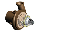
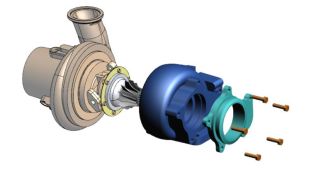
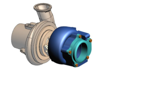
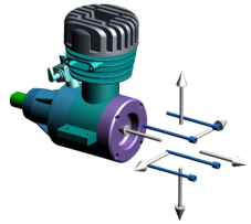
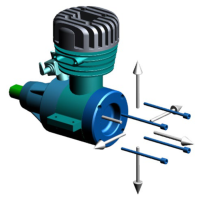
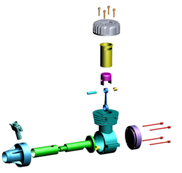
The Edit 3D feature provides the ability to modify the positions of the parts. The modification
(translation) is manually defined by dragging a handler in the 3D annotation. This feature makes it
possible to enhance the understanding of assemblies and to create exploded views when required.
Check the “Activate transform mode” mark
Select a part (or several parts) in the 3D annotation
Note: The transform feature supports the “multiple selection” mode as well as the standard Acrobat one. The visibility status of the selected parts can be changed after a displacement.
Click the arrow of the handler corresponding to the displacement direction and
Move the handler while keeping the mouse button pressed to move the selected parts
Use the three values (Axis 1, Axis 2, Axis 3) as indications of the current displacement
Click one or several times on “Change handler size” to temporarily resize the handler if required
Selected an already displaced part and click “Reset initial position” to position back the part to its initial position
Note
The handler is dimensioned based on the size of the global bounding box calculated with
all the parts, independently of their visibility status.
Remark:
The modified positions of parts can be saved as Acrobat views.
It is mandatory to use the “Create view” feature to create an Acrobat view.
The view can be created:
without unselecting the parts (When the view is created, the handler will be automatically excluded and the selected part will also be temporarily displayed as unselected)
The transformed parts remain selected after a displacement enabling thus to add parts
to the selection set and continue the displacement definition.
To clear the selection set, juts click in the 3D annotation.
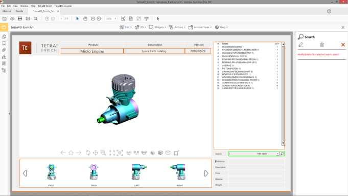
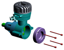
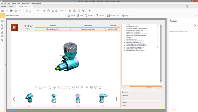
In Edit mode, all the settings related to the item are accessible in the Edit panel.
When deleting an item, a confirmation dialog box appears, so that it is possible to
confirm or cancel the operation.
Once an item has been deleted, it is not possible to undo the operation.
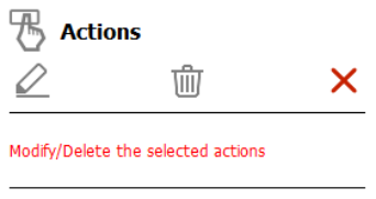
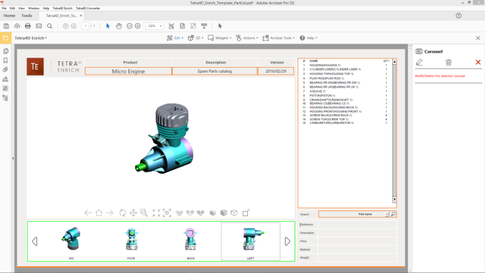
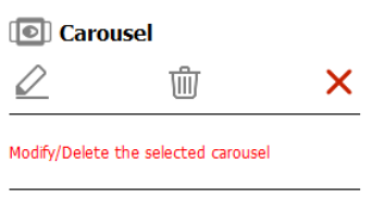
Click on the “Modify the selected item” icon to edit the Carousel properties, or
Click on the “Delete the selected item” icon to delete the Carousel, or
Click on the “Leave the edit mode” to cancel the operation.
If the “Modify the selected item” option has been chosen, refer to the Carousel definition
section for detailed explanations about the Carousel settings.
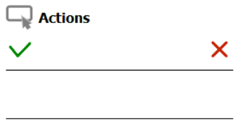
Click on the green check to accept the modification, or
In Edit mode, all the settings related to the item are accessible in the Edit panel.
When deleting an item, a confirmation dialog box appears, so that it is possible to
confirm or cancel the operation.
Once an item has been deleted, it is not possible to undo the operation.
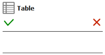
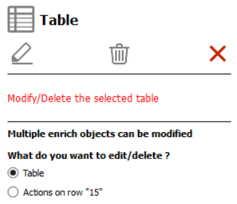
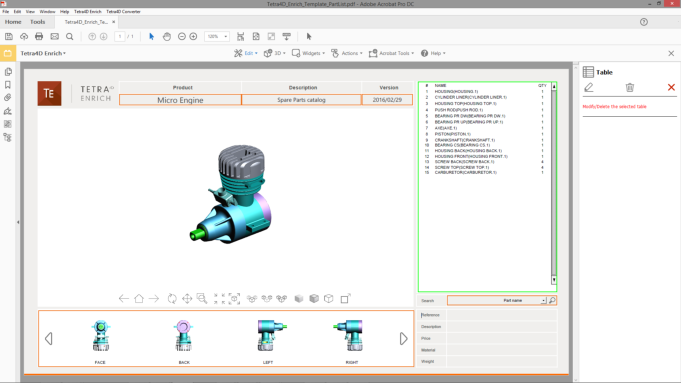
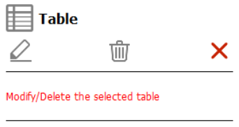
Click on the “Modify the selected item” icon to edit the table properties, or
Click on the “Delete the selected item” icon to delete the table, or
Click on the “Leave the edit mode” to cancel the operation.
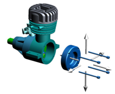
In Edit mode, all the settings related to the item are accessible in the Edit panel.
When deleting an item, a confirmation dialog box appears, so that it is possible to
confirm or cancel the operation.
Once an item has been deleted, it is not possible to undo the operation.
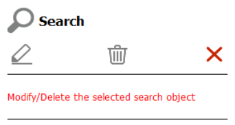
Click on the “Modify the selected item” icon to edit the Search widget properties, or
Click on the “Delete the selected item” icon to delete the Search widget, or
Click on the “Leave the edit mode” to cancel the operation.
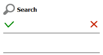
If the “Modify the selected item” option has been chosen, refer to the Search widget
definition section for detailed explanations about the Search widget settings.
Click on the green check to accept the modification, or
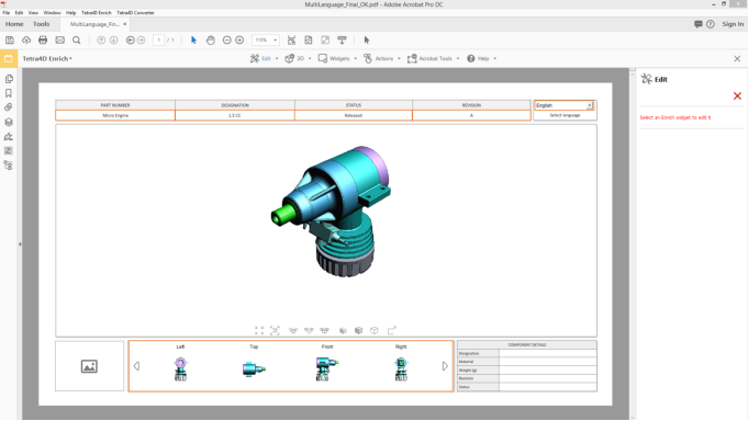
In Edit mode, all the settings related to the item are accessible in the Edit panel.
When deleting an item, a confirmation dialog box appears, so that it is possible to
confirm or cancel the operation.
Once an item has been deleted, it is not possible to undo the operation.
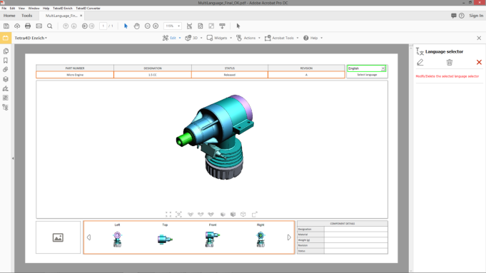
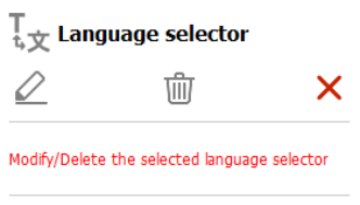
Click on the “Modify the selected item” icon to edit the Language widget properties, or
Click on the “Delete the selected item” icon to delete the Language widget, or
Click on the “Leave the edit mode” to cancel the operation.
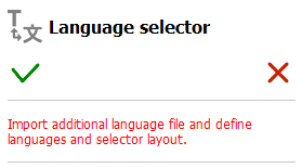
If the “Modify the selected item” option has been chosen, refer to the Language selector
widget definition section for detailed explanations about the Language widget settings.
Click on the green check to accept the modification, or
If the “Modify the selected item” option has been chosen, refer to the Action definition
section for detailed explanations about all the different actions settings.
Click on the green check to accept the modification, or
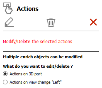
Select the highlighted 3D annotation in which the activation of a 3D view or the selection of any 3D part was defined as the trigger of the actions to be modified.
All the 3D annotations having assigned actions are highlighted in orange.
Once the 3D annotation has been selected, it is highlighted in green.
If required, select the trigger of the actions that must be modified.
Different types of triggers can be defined from events occurring in a 3D annotation:
the activation of any 3D view or by the activation of a specific 3D view.
the selection of any 3D part.
If some actions have been defined with these two types of triggers, the sidebar offers
first to select the trigger.
Selection of the trigger in case of multiple choices
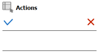
Click on the “Modify the selected item” icon to edit the actions, or
Click on the “Delete the selected item” icon to delete all the actions assigned to this button, or
Click on the “Leave the edit mode” to cancel the operation.
If the “Modify the selected item” option has been chosen, refer to the Action definition
section for detailed explanations about all the different action settings.
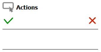
Click on the green check to accept the modification, or
If the “Modify the selected item” option has been chosen, refer to the Action definition
section for detailed explanations about all the different actions settings.
Click on the green check to accept the modification, or
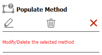
If the “Modify the selected item” option has been chosen, refer to the description of the
“Set populate method for text fields” for detailed explanations about the populate text
field method settings.
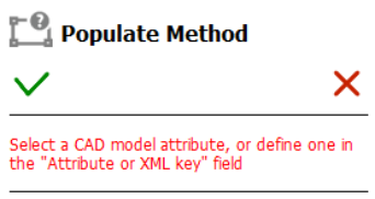
Click on the green check to accept the modification, or
Click on the red “X” to cancel.
Conversation saved
FOURDY BETA
Hello! I'm FOURDY
Your multilingual generative AI assistant for documentation. Ask me anything about Tetra4D Enrich in your own language, or choose a sample question below to start a conversation:
What is Tetra4D Enrich?
What are the latest release notes for Tetra4D Enrich?
How do I start evaluating Tetra4D Enrich?
How can I get assistance?
FOURDY may store conversations according to OpenAI's policy. Responses may not always be accurate.

 : Modify the selected item.
 : Delete the selected item.
 : Leave the Edit mode.
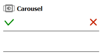

 : Modify the selected item.a
 : Delete the selected item.