
Actions
The Actions menu allows you to define interactivity between different items within the PDF document, for example:
Clicking a button will activate a 3D view and will display text in a text field,
Selecting a part in the 3D annotation (or in the part list) will display several attributes of the part in different text fields.
The actions are defined first by a trigger, and secondly by the operation that will be executed afterwards.
Overview
The actions can be triggered by several means:
On button: the interactivity is triggered by a click on a button.
On 3D view: the interactivity is triggered by the activation of an existing 3D view.
On 3D part: the interactivity is triggered by the selection of any part in the 3D annotation.
On table row: the interactivity is triggered by the selection of a row in a table.
The actions that can be executed afterwards are:
Activate View: Activates a specified 3D view.
Previous View: Activates the previous 3D view.
Next View: Activates the next 3D view.
Render Mode: Activates a chosen render mode.
Node Color: Sets a predefined color and transparency to a specified 3D part.
Node Visibility: Changes the visibility of a selected 3D part.
Set Text In Field: Outputs text to a text (or a button) field.
Show Image: Displays an image in a button.
Set Link: Opens a link (attachment, page within the PDF, URL).
Rotate: Changes the mouse main control (left button) to Rotate mode (which is the default mode).
Pan: Changes the mouse main control (left button) to Pan mode.
Zoom: Changes the mouse main control (left button) to Zoom mode.
Fit Visible: Displays all the visible parts and reset the center of rotation point in the view.
Fit Selected: Adjusts the zoom in the 3D annotation to fit to a selected 3D part.
Full Screen Mode: Toggle the display mode of the document to full screen / document modes.
Remark:
This section will first present the different triggers and then all the possible actions.
Actions > On Button
The actions will be triggered by pressing a button present in the PDF document.
Note
The buttons must be defined prior to the creation of the action. Refer to “Add button” for instructions on how to create buttons.
- Within the Tetra4D Enrich toolbar, choose Action > On ButtonNote: The existing buttons in the active page of the PDF document are highlighted:
In orange, if no action has been defined on the button,
In green if an action has already been defined.
- Select the button.Note: Once selected, the button is highlighted in green.
- In the Actions panel, which appears on the right, define the name of the sequence of actions (optional).Note: Several actions can be created in one sequence.
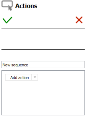
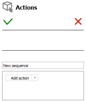
The Actions panel corresponding to the “On button” trigger
- Use the drop-down list “Add action” to select the action to be executed.Note: refer to Description for actions for explanations on the different types of actions.
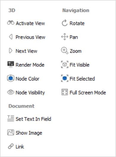
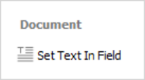
The different types of actions available for the “On button” trigger
- Define the action properties in the action panel that appears.Note: refer to Description for actions for explanations on the different types of actions.
Click on the “Add action” drop down list to add a new action to the current sequence of actions, or
Click the green check to save the action, or
Click the red “X” to cancel the operation.
Actions > On 3D view
The activation of an existing 3D view can be used to trigger interactivity inside the PDF document. The views must be defined in the 3D annotation prior the creation of the action.
Within the Tetra4D Enrich toolbar, choose Action > On 3D view.
- Select the 3D annotation (if several are present in the active page of the PDF document).Note: If the active page contains only one 3D annotation, the 3D annotation is automatically selected and highlighted in green.
In the Actions panel that appears in the right, click on the “Trigger view name” drop down list to select the 3D view that will trigger the action.
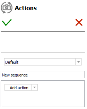
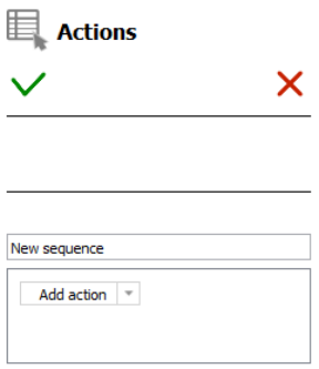
The Actions panel for a “On 3D view” trigger
- Define the name of the sequence of actions (optional).Note: Several actions can be created in one sequence.
- Click on the “Add action” drop down list to select the action to be executed.Note: refer to Description for actions for explanations on the different types of actions.
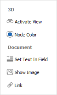
The different types of actions available for the “On 3D view” trigger
- Define the action properties in the action panel that appears.Note: refer to Description for actions for explanations on the different types of actions.
Click on the “Add action” drop down list to add a new action to the current sequence of actions, or
Click the green check to save the action, or
Click the red “X” to cancel the action.
Actions > On 3D part
The selection of a part in the 3D annotation or the selection of a row in a part list (flat) or part list (hierarchical) table can be used to trigger interactivity inside the PDF document.
Within the Tetra4D Enrich toolbar, choose Action > On 3D part.
- Select the 3D annotation (if several are present in the active page of the PDF document).Note: If the active page contains only one 3D annotation, the 3D annotation is automatically selected and highlighted in green.
In the Actions panel that appears in the right, define the action name (optional).
The Actions panel for a “On 3D part” trigger
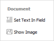
- Click on the “Add action” drop down list to select the action to be executed.Note: refer to Description for actions for explanations on the different types of actions
The different types of actions available for the “On 3D view” trigger
- Define the action properties in the action panel that appears.Note: refer to Description for actions for explanations on the different types of actions
Click on the “Add action” drop down list to add a new action to the current sequence of actions, or
Click the green check to save the action, or
Click the red “X” to cancel the action.
Actions > On table row
The selection of a row in a table can be used to trigger interactivity inside the PDF document.
Within the Tetra4D Enrich toolbar, choose Action > On table row
- Select the row in the table.Note: The table is highlighted in orange before selection.When clicking a table, the row is selected and highlighted in green.If needed, it is possible to click another row from the same table.
- Define the name of the sequence of actions (optional).Note: Several actions can be created in one sequence.
The Actions panel for a “On table row” trigger
- Use the drop-down list “Add action” to select the action to be executed.Note: refer to Description for actions for explanations on the different types of actions.
The different types of actions available for the “On table row” trigger
- Define the action properties in the action panel that appears.Note: refer to Description for actions for explanations on the different types of actions.
Click on the “Add action” drop down list to add a new action to the current sequence of actions, or
Click the green check to save the action, or
Click the red “X” to cancel the action.
Description of actions
This section presents the different types of actions and their related parameters.
Activate View
This action activates an existing 3D view.
In the Add action drop down list, select the Activate View menu.
- Select the 3D annotation (if several are present in the active page of the PDF document).Note: If the active page contains only one 3D annotation, the 3D annotation is automatically selected and highlighted in blue.
- Select the view to be activated from the list of views.Note: The list shows all the existing views for the selected 3D annotation.
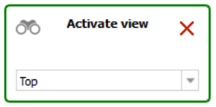
Activate view action definition panel
Click the green check at the top of the Actions panel to save the action, or
Click the red “X” in the “Activate view” panel to delete this action and keep the action definition panel open, or
Click the red “X” at the top of the Actions panel to cancel the action definition.
Previous View / Next View
These actions activate the Previous or the Next view in the 3D annotation.
In the Add action drop down list, select the Previous View or Next View.
- Select the 3D annotation (if several are present in the active page of the PDF document).Note: If the active page contains only one 3D annotation, the 3D annotation is automatically selected and highlighted in blue.
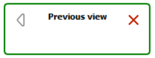
Previous view action definition panel
Click the green check at the top of the Actions panel to save the action, or
Click the red “X” in the “Previous view” or “Next view” panels to delete the action and keep the action definition panel open, or
Click the red “X” at the top of the Actions panel to cancel the action definition.
Render Mode
This action enables you to activate a specified render mode in the 3D annotation.
It is meant to provide the user with simple and direct access to common 3D render modes by clicking a button instead of using the standard tools available in the 3D annotation toolbar.
It is for example possible to put a few buttons in the PDF document to change the render mode to the most used modes (Solid, Solid outlined, Illustration…)
In the Add action drop down list, select the Render Mode menu.
- Select the 3D annotation (if several are present in the active page of the PDF document).Note: If the active page contains only one 3D annotation, the 3D annotation is automatically selected and highlighted in blue.
- Select the render mode to be activated from the render mode drop down list.Note: The list shows the available render modes.
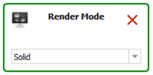
Render Mode action definition panel
Click the green check at the top of the Actions panel to save the action, or
Click the red “X” in the “Render Mode” panel to delete this action and keep the action definition panel open, or
Click the red “X” at the top of the Actions panel to cancel the action definition.
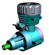
|
|
|
|
|
|---|---|---|---|---|
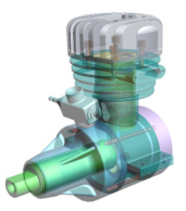
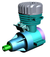
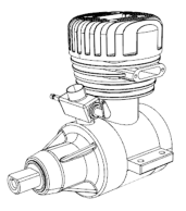
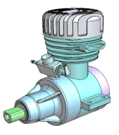
Solid |
Solid outlined |
Illustration |
Shaded illustration |
Transparent |
Node Color
This action enables you to highlight a part (or a group of part) by temporarily changing their color or transparency.
Note
This action is not generic because it applies to some selected 3D parts that are only present in the current PDF document.
In the Add action drop down list, select the Node Color menu.
- Select the 3D annotation (if several are present in the active page of the PDF document).Note: If the active page contains only one 3D annotation, the 3D annotation is automatically selected and highlighted in blue.
- Select a part in the 3D annotation or in the data tree.Note: It is possible to select a group of parts by selecting a node in the data tree (i.e.: selection of a sub-assembly containing several parts).
Select in the Color drop-down list the color to be applied to the selection.
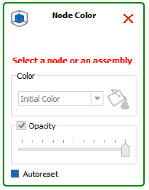
Node Color action definition panel
- Define the transparency value to be applied to the selection by moving the Opacity slider.Note: it is possible in the same Node Color action to sequentially select different parts to change their color and transparency (different colors and transparency settings).
Uncheck the “Autoreset” mark if you don’t want the initial part color and transparency to be restored when other actions will be triggered.
Click the green check at the top of the Actions panel to save the action, or
Click the red “X” in the “Node Color” panel to delete this action and keep the action definition panel open, or
Click the red “X” at the top of the Actions panel to cancel the action definition.
Node Visibility
This action enables to change the visibility of parts in the 3D annotation.
It is meant to provide the user with simple and direct access to common node visibility modes by clicking a button instead of using the contextual menus that are available in the 3D annotation.
It is for example possible to put a few buttons in the PDF document to change the visibility of selected parts (Isolate, Hide, Show all parts).
Note
The Hide and Isolate actions will apply on the parts that are selected in the 3D annotation. The Show all action doesn’t require any selection in the 3D annotation.
In the Add action drop-down list, select the Node Visibility item.
- Select the 3D annotation (if several are present in the active page of the PDF document).Note: If the active page contains only one 3D annotation, the 3D annotation is automatically selected and highlighted in blue.
- Select the operation to be executed from the node visibility drop down list.Note: The list offers 3 operations:
Hide: Hides the selected part.
Show all: Show all the parts that are present in the 3D annotation.
Isolate: Isolates the selected part (Hide all the parts except the selected one).
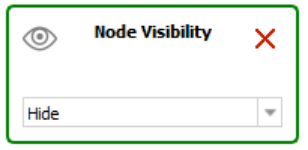
Node Visibility action definition panel
Click the green check at the top of the Actions panel to save the action, or
Click the red “X” in the “Node Visibility” panel to delete this action and keep the action definition panel open, or
Click the red “X” at the top of the Actions panel to cancel the action definition.
Set Text in Field
This action enables you to output a text in a text field or in a button.
Note
The text fields must be defined prior the creation of the action. Refer to “Add text field” for instructions on how to create text fields.
Note
When triggered by an “On button”, “On 3D view”, or “On table row” event, the “Set text In Field” action enables output of predefined text (static) in a text field. When triggered by a “On 3D part” event (selection of a part in the 3D annotation), the “Set text In Field” action can write static text or information about the selected part (CAD attributes or imported attributes) to a text field.
In the Add action drop down list, select the Set Text in Field menu.
- Select a text field or a button (where the text will be displayed).Note: All the buttons and text fields from the active page are highlighted in orange.Once selected, the text field or the button is highlighted in blue.
Define the text to be displayed: static text
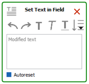
Set Text in Field action definition panel
Define the text in the “Modified text” area.
 : Click on the Undo / Redo icon if required.
 : Click on the different options to control the display of the text (Bold, Italic, Underlined).
Or define the 3D part attribute to be displayed in the text field:
 : Click on the “Add selected Attribute into the text area.”
Select the attribute in the list of attributes.
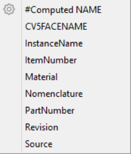
List of existing attributes
Note: After its selection in the list of available attributes, the attribute is identified in the text definition area as follows:
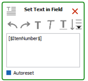
Set Text in Field action definition panel showing an attribute linked to the CAD part
Uncheck the “Autoreset” mark if you don’t want the text field being restored (emptied) when other actions will be triggered.
Click the green check at the top of the Actions panel to save the action, or
Click the red “X” in the “Set Text in Field” panel to delete this action and keep the action definition panel open, or
Click the red “X” at the top of the Actions panel to cancel the action definition.
Show Image
This action enables you to output an image in a button.
Note
The button must be defined prior the creation of the action. Refer to “Add button” for instructions on how to create text fields.
In the Add action drop down list, select the Show Image menu.
- Select a button (where the image will be displayed).Note: All the buttons from the active page are highlighted in orange.Once selected, the button is highlighted in blue.
Click the image icon in the Change Image panel.
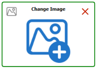
Show Image action definition panel
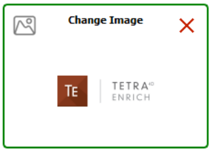
- Use the Select image dialog to select to browse to the image file.Note: it might be required to change the default file extension in the File open dialog to be able to select an image file.Note: After the selection of the image, a preview appears in the Change Image panel.
Click the green check at the top of the Actions panel to save the action, or
Click the red “X” in the “Set Text in Field” panel to delete this action and keep the action definition panel open, or
Click the red “X” at the top of the Actions panel to cancel the action definition.
Set link
This action enables you to define different types of links that can be accessed by various events. The supported links are:
Attachment: Opens a document that is attached in the current PDF document.
Page: Shows the specified page in the current PDF document.
Web URL: Opens a Web URL in a Web browser.
In the Add action drop down list, select the Set Link menu.
Select the type of link to be defined.
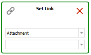
Set Link action definition panel
- Select Attachment to specify an attached file and then select a file in the drop-down list.Note: The drop-down list shows the files that are already attached in the PDF document.
Or Select Page and type in the page number in the input field.
- Or select Web URL and type in the URL in the input field.Note: The Web URL is not tested when the action is saved.
Click the green check at the top of the Actions panel to save the action, or
Click the red “X” in the “Set Text in Field” panel to delete this action and keep the action definition panel open, or
Click the red “X” at the top of the Actions panel to cancel the action definition.
Rotate / Pan / Zoon
These actions enable users to change the 3D operation accessed by using the left mouse button.
It is meant to provide the user with simple and direct access to the main 3D operations which control the display of the model (rotation of the 3D, Pan, zoom in and out).
It is for example possible to define buttons in the PDF document to give to the user access to these three operations by clicking the buttons, instead of using the standard 3D toolbar or 3D controls accessible through the left and right mouse buttons.
Note
These actions are directly executed and don’t require any selection in the 3D annotation.
In the Add action drop down list, select the Rotate (or Pan or Zoom) menu.
- Select the 3D annotation (if several are present in the active page of the PDF document).Note: If the active page contains only one 3D annotation, the 3D annotation is automatically selected and highlighted in blue.
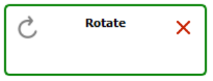
Rotate action definition panel
Click the green check at the top of the Actions panel to save the action, or
Click the red “X” in the “Rotate” panel to delete this action and keep the action definition panel open, or
Click the red “X” at the top of the Actions panel to cancel the action definition.
Fit visible
This action enables users to execute a Fit Visible operation in the 3D annotation.
This action is meant to provide users with simple and direct access to the Fit Visible operation to adjust the zoom so that all the currently visible parts will be visible in the 3D annotation and will also reset the center rotation point of the part/model.
It is for example possible to define a button in the PDF document to give to the user access to this Fit Visible operation by clicking the button, instead of using the standard 3D toolbar or the contextual menus that are available in the 3D annotation.
Note
This action is directly executed and doesn’t require any selection in the 3D annotation.
In the Add action drop down list, select the Fit Visible menu.
- Select the 3D annotation (if several are present in the active page of the PDF document).Note: If the active page contains only one 3D annotation, the 3D annotation is automatically selected and highlighted in blue.
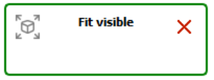
Fit visible action definition panel
Click the green check at the top of the Actions panel to save the action, or
Click the red “X” in the “Fit visible” panel to delete this action and keep the action definition panel open, or
Click the red “X” at the top of the Actions panel to cancel the action definition.
Fit selected
This action enables to execute a Fit Selected operation in the 3D annotation.
This action is meant to provide users with simple and direct access to the Fit Selected operation so that the zoom will be adjusted to make the selected part fit to the 3D annotation.
It is for example possible to define a button in the PDF document to give to the user access to this Fit Selected operation instead of using the contextual menus that are available in the 3D annotation.
Note
This action requires a part to be selected in the 3D annotation.
In the Add action drop down list, select the Fit Selected menu.
- Select the 3D annotation (if several are present in the active page of the PDF document).Note: If the active page contains only one 3D annotation, the 3D annotation is automatically selected and highlighted in blue.
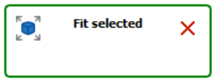
Fit selected action definition panel
Click the green check at the top of the Actions panel to save the action, or
Click the red “X” in the “Fit Selected” panel to delete this action and keep the action definition panel open, or
Click the red “X” at the top of the Actions panel to cancel the action definition.
Full Screen Mode
This action toggles full screen mode.
This action is meant to provide users with simple and direct access to the Full Screen Mode operation so that the document is displayed in full screen, and then can be displayed back inside Acrobat Pro or Acrobat Reader®.
It is for example possible to define a button in the PDF document to directly toggle the display mode, instead of using the top menu or the contextual menu that are available in the 3D annotation or the CRTL + L shortcut.
Note
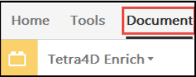
This action is directly executed and doesn’t require any selection in the 3D annotation. The activation of the full screen mode works only when no Acrobat Pro plug-in is open, including Tetra4D Enrich or Tetra4D Converter. In addition, none of the Acrobat Tools can be open. To close all plug-ins and tools, select the “Document” from the Acrobat menu bar as show in the image below.
In the Add action drop down list, select the Full Screen Mode menu.
- Select the 3D annotation (if several are present in the active page of the PDF document).Note: If the active page contains only one 3D annotation, the 3D annotation is automatically selected and highlighted in blue.
Full Screen Mode action definition panel
Click the green check at the top of the Actions panel to save the action, or
Click the red “X” in the “Full Screen Mode” panel to delete this action and keep the action definition panel open, or
Click the red “X” at the top of the Actions panel to cancel the action definition.