
Analyzing product design
The tools accessible in the Design Review tab are dedicated to design-review work. Calculations for analysis can be precise, based on exact geometry defined by the original CAD file. Or, calculations can be approximate, based on the level of detail set for the display.
Calculating bounding boxes
A bounding box is a rectangular wireframe entity that encloses the selected components. The active coordinates system (Main CS) determines the orientation of the bounding box faces. Each segment of a bounding box is also an entity.
Bounding boxes are calculated from geometric elements. You can make bounding boxes of a part, multiple parts, assemblies, or subassemblies. Bounding boxes appear under the Models branch of the Model Tree structure. You can hide or show bounding boxes or individual segments, as needed. You can also rename them. Each segment of a bounding box is an entity. Tetra4D Reviewer gives default names to the bounding boxes and segments. You can change the names in the Model Tree after you create the bounding box.
Calculating a bounding box
Click
 in DESIGN REVIEW tab, and the following dialog box appears:
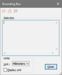
Select options for displaying units with the bounding box wireframe:
Choose the measurement system in the Unit menu.
Select Display Unit to display the units of measurements with the dimensions, or deselect it to see the dimension values alone.
Note: The unit options apply only to bounding boxes created with the middle button, Create Bounding Box with Dimension.
Select the parts or assemblies that you want to enclose in the bounding box.
Note: The Selection area displays the volume and X, Y, and Z dimensions of the bounding box.
Click to create bounding boxes:
Create bounding box
 , to create a wireframe bounding box.
Create bounding box With Dimension
 , to create a wireframe bounding box that displays each dimension measurement.
Create Gravity Center
 , to create a point entity for the center of gravity of the bounding box. Each click creates a new bounding box.
You can create bounding boxes for other parts without closing the dialog box: Select a different part, parts, or assemblies in the document pane or Model Tree. Then click buttons for the types of bounding boxes you want to create.
Accessing the bounding box information
In the Model Tree, select an existing bounding box or bounding box segment.
Click
in DESIGN REVIEW tab.Note: Information about the selected element appears in the Selection area.
As needed, choose an option on the Unit menu to change the units of measurements for the Selection area.
Select another bounding box or segment to review it or close the Bounding Box controls window.
Note: You can select and copy information in the Selection area, but it can’t be edited.
Measuring and dimensioning
About measurements and dimensions
Dimensions are annotations that represent distances, angles, or coordinates in the 3D window. These
entities are saved as part of the session file. They appear in the Model Tree and in the document
pane. You can select, hide, show, and view the properties for a dimension.
A measurement is like a dimension except that they appear only temporarily. When you click
anywhere in the document pane or Model Tree, the measurement disappears.
Measuring and dimensioning involve selecting specific geometries rather than entire parts. Selection
filters and the Accept/Reject  pointer help you select exactly the elements that you want to use as
your start and end points.
pointer help you select exactly the elements that you want to use as
your start and end points.
Selection filters for geometric selections
The selection filters control the snap-to behaviors when you click a point in the 3D display area. When a specific selection filter is inactive, clicking ignores that type of geometry. When the same selection filter is active, clicking snaps to and selects the nearest geometry of that type. When all selection filters are active, clicking selects any type of geometry close to the location you click. For example, if you want to select only edges, you can disable the selection filters for points, faces, and solids.
Selection filters sometimes adjust automatically. For example, when the Radius measurement tool is active, the Points, Faces, and Solids filters are deselected. The Edges filter remains active so that you can select only geometries appropriate for a radius measurement.
Types of selection filters
In DESIGN REVIEW tab, activate one or several of the selection button:
 : Snaps to vertices and points.
 : Snaps to edges, curves, and coordinates systems axes.
 : Snaps to faces from solids, surfaces, and planes.
 : Snaps to solids.
 : Collapsed branches of the Model Tree can be selected. The full collapsed branch is selected if one part from that branch is selected in the display area.
 : Highlights entities as the pointer moves over the display, before you click to select.
Note: Selection filters don’t affect selections in the Model Tree.
Automatic changes in selection filters
Selection filters sometimes adjust automatically as you perform specific tasks. These automatic adjustments leave on the filters that are appropriate for that task and turn off the other filters. For example, when the Radius measurement tool is active, the Points, Faces, and Solids filters are deselected. The Edges filter remains active so that you can select only geometries appropriate for a radius measurement. The selectable entities can be explicit or implicit. Implicit entities are characteristic entities extracted from another entity. For example, the center point for a circular edge is an entity that is implicit for the edge.
Confirming geometric selections with the Accept/Reject pointer
When you select geometries in the display rather than parts, clicking can be ambiguous. For example,
clicking close to the circular edge of a cylindrical solid can select various geometric objects. It can
select a point, a face, the circumference, or an axis running vertically through the cylinder. In
situations like that example, a Accept/Reject pointer icon appears. This icon gives you the
opportunity to use the left and right mouse buttons to accept or reject a series of possible selections.
When you click the right mouse button, the first possibility is rejected and the selection changes to
the next possibility. Clicking the right mouse button repeatedly cycles through all the possible
selections and back to the first one.
When the element that you want to select is highlighted, clicking the left mouse button confirms the
selection and restores the default pointer icon.
The active selection filters influence which types of geometries are shown as possibilities.
Measurement tools
The types of measurement correspond to the tools in the Dimension control window.
Distance
 measures on a straight-line between two elements that you select, such as points, lines, surfaces, and axes.
Radius
 measures the distance between a center point and an arc.
Diameter
 measures the distance across the center point of a circle.
Length
 measures the distance along an edge or curve. Length markups look like a standard distance dimension, with two lines attached to the extremities of the dimension entity. If the measured entity is not a line, only one attachment line appears, connecting the dimension with the middle of the selected entity.
Angle
 measures the angle between two geometric elements.
Orientation
 The angle between a selected edge, curve, axis, or face and a reference plane. The reference plane is perpendicular to the active axis of the current coordinates systems. For example, if X is active, YZ is the reference plane.
Coordinates
 Identifies the x, y, and z coordinates for a point. Note: Coordinates are calculated according to the active coordinates system. The Lock option in the Dimension controls window creates an absolute reference. Locking disables the automatic update that occurs when you change the coordinates system.
Minimum/Maximum distance
 The maximum distance is a measurement between an infinite planar reference and a part. The reference is the plane that is perpendicular to the active axis of the current Main CS. Measuring a distance, an angle, or coordinates of a points As you select elements for a measurement, notice the information in the status bar. The status bar provides cues about each step of the selection process. These cues vary according to which measurement tool is active.
Click
 in DESIGN REVIEW tab
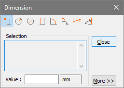
Select a measurement type.
Set the Selection Filters if required
- , to snap to vertices and points on a part.
- : to snap to edges, curves, and axes.
- : to snap to faces
- : Snaps to surfaces solids.
Note: You can select multiple Selection Filters. Some filters are automatically deselected and unavailable for specific tools.
Click More, and select Dimension options, as needed.
Note: Selecting the Saved option creates a dimension annotation that is saved with the session file. Measurements you make with Saved deselected appear only temporarily.
In the document pane or Model Tree, select the first location or geometric element for the measurement.
Note: Some tools present an Accept/Reject
selection pointer that you use to toggle
through selection possibilities.If necessary, use the context menu to change the orientation of the 3D objects, and then select a second element for the measurement.
If Attach is selected, click the dimension annotation to set its location in the document pane. As needed, drag the dimension to reposition it.
The context menu holds four view commands you can use during the process of creating a dimension: Fit Visible, Undo Fit All, Redo, and Restore Config. View.
Modifying the Dimensioning options
By default, the Dimension controls window opens with only the tool buttons and Selection area shown. Clicking the More button expands the windows so that you can see more options, such as Saved and Attach.
Measurement tool buttons Determines the type of measurement.
Selection Displays information available about the selected element, such as the part name and geometry.
Value Displays the measurement result.
Note: You can edit the measurement result. For example, you can enter a comment in the dimension or force a specific value.
Saved When selected, creates a permanent annotation of the measurement.
Attach Creates lines in the document connecting the dimension markup to the locations being measured. You can drag an attached dimension within the display. When deselected, the dimension markup appears on the measurement.
Units Defines the units of the dimension. The default units are those read from the CAD file data or set as session units in General Preferences.
Real Creates the actual measurement.
Along X, Along Y, and Along Z Creates measurements of the x, y, and z projections of the Real measurement. Labels in the document pane identify projection measurements as dx, dy, and dz components. When Saved is active during the measuring, the x, y, and z projections are saved as independent entities and appear in the Model Tree. Projections are calculated according to the active coordinates system.
Display Units Shows the value and unit of measurement together in the markup.
Font Opens the Font dialog box, for selecting font characteristics.
Editing a dimension
After you create a dimension, it appears in the Model Tree under the Dimensions portion of the Annotations structure. You can change the appearances and behaviors of some dimensions.
In either the Model Tree or document pane, right-click the dimension and choose Edit.
Edit the dimension:
To change the value displayed for the dimension, type new text or numbers in Value.
To move the dimension markup, select Attach (or deselect and then select again). Click to set the new position for the markup.
(For Coordinates only.) Select or deselect Along X, Along Y, and Along Z for the projection of the dimension along the Main CS.
To tie a Coordinates dimension to the current Main CS, select Lock. To automatically update the dimension when another Main CS is activated, deselect Lock.
To change the measurements units, select from the Units menu.
To show the units as part of the annotation, select Insert. To hide the units, deselect Insert.
To change the font characteristics for the annotation, click Font and select options.
You can quickly change the text of a dimension by clicking its text in the Model Tree and typing.
Modifying the position of a dimension
In either the Model Tree or document pane, select the dimension.
Right-click the dimension, and choose Move.
Move the pointer to reposition the dimension annotation, and click to set the new position.
Showing and hiding annotations
In either the Model Tree or document pane, right-click the dimension or markup and choose
Show/Hide.
Calculating physical properties
The Physical Properties dialog box provides features to calculate areas, volume, mass, and the center of gravity for parts and assemblies. All these calculations are performed simultaneously. It’s important to remember the distinction between Properties and Physical Properties. Properties are persistent characteristics for individual entities. Physical Properties temporarily displays calculations. These calculations are based on Properties values and the geometry of the selected parts. You can save Physical Properties calculation results by exporting them.
Calculating physical properties
You can save calculations only by exporting results to a text file. Otherwise, the Physical Properties information clears itself when you close or click outside Physical Properties.
Select the entities in the document pane or Model Tree.
Click
 in DESIGN REVIEW tab
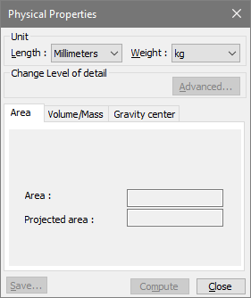
Click Advanced, and change the precision level, as needed.
Click Compute.
Review the results on the Area, Volume/Mass, and Gravity Center tabs.
(Optional) Click Save and choose a location and filename for the text file of the calculations.
You can calculate physical properties for one entity after another without closing Physical Properties. After you finish one calculation, select a different part in the Model Tree or document pane, and click Calculate again.
Physical Properties calculation results
When you calculate physical properties, the results appear on the three tabs that run across the lower area of the Physical Properties.
Area tab
Area Shows the surface area of physical parts (the area you could cover with paint).
Projected Area are calculated according to the active axis of the current coordinates system.
Volume/Mass tab
Volume Physical volume of the selected parts.
Density Value of the Density property for the selected parts, as specified in the Properties. If the parts have different densities, the Density physical property appears as Various.
Mass Calculation result based on the volume and density values.
Gravity Center tab
X, Y, and Z Coordinates of the center of gravity for the selected parts.
Advanced options for Physical Properties calculations
The Advanced button in Physical Properties opens a dialog box with precision options. Settings you select in the Advanced dialog box apply only to the next calculation. If you close the Physical Properties or select different parts, the detail level reverts to a default setting. Note: Level of Detail options are also available on the Graphics preferences. As preference settings, the options you choose apply globally.
User Defined
When selected, these options are available:
Precision list Includes Extra Low, Low, Medium, High, and Extra High. When you select one of these levels, the Chord Height Ratio and Wireframe Chord Angle change to preset values for the selected level.
Chord Height Ratio Specifies the percentage of bounding box used to compute chord height.
Wireframe Chord Angle Specifies the maximum angle between two contiguous segments of wire edges for every face. The value must be from 10 through 40.
Note: If you change your selection in the precision list after you adjust the Chord Height Ratio or Wireframe Chord Angle, those changes are lost.
Controlled Precision
When selected, these options are available:
Wireframe Chord Angle (As described under User Defined.)
Maximum Chord Height Specifies the maximum distance between surface and tessellation.
Minimal Triangle Angle Specifies the angle between two contiguous segments of wire edges for every face. Allowable values range from 10 through 30.
Managing custom coordinates systems
By default, all session files inherit a global coordinates system from the original CAD source file. This coordinates system is listed under Coordinates in the Model Tree as CAD CS. When you open a session file, the default coordinates system is always active. You can’t delete, move, edit, or rename these default global coordinates. You can define and save additional coordinates systems with the orientation and origin that you specify. Coordinates systems are especially important for sectioning, dimensioning, displacement of parts, and controlling standard views.
Creating a coordinates system
Click
 in DESIGN REVIEW tab.
Select Create Coordinates System
 .
.Select a method option and set any required geometry.
Note: To undo geometry selections, click Reset and select different geometry.
The custom coordinate system appears as Axis X under Coordinates Systems in the Model Tree.
Renaming a coordinates system
In the Model Tree, right-click the custom coordinates system and choose Rename.
Type a name.
Activating a coordinates system and a specific axis
Two roles apply to coordinates systems: Main CS and View CS. You can assign both roles to the same coordinates system or assign the roles to different coordinates systems.
Expand the Coordinate Systems structure in the Model Tree so that you can see the available coordinates systems.
Right-click the coordinates system and choose its role:
Main CS Serves as the reference environment for measurements and calculations. The Main CS is the active coordinates system.
View CS Serves as the reference for Default Views. Solid arrow shapes in the lower left corner of the document pane represent the current View CS.
- (Optional) Right-click the Main CS coordinate system and choose Direction > and X, Y, or Z to change the main axis.Assigning a role to a custom coordinate system temporarily changes its name in the Model Tree to Main CS (Z) or View CS.If you activate a custom coordinates system in both ways, its name becomes View & Main CS(Z).The custom coordinates system reverts to its original name when you assign the roles to a different coordinates system.When you assign the Main CS or View CS role to the CAD CS, the name doesn’t change.
Note: Simply selecting a coordinates system in the Model Tree highlights the three lines indicating the axes in the document pane. However, selecting or double-clicking doesn’t activate that coordinates system in any role.
Changing the visibility of a coordinates system
Coordinates system axes is represented in the 3D area by triedron located at its origin point.
In the Model Tree, expand the Coordinates Systems so that you can see the CAD CS and all custom coordinates systems.
Right-click the coordinates system that you want to view, and choose an item from the context menu:
Isolate Hides all entities except the coordinates system.
Hide/Show Toggles the visibility of the axes.
Focus Zooms in on the origin point.
Show Me Draws a circular highlight around the origin point.
Deleting a coordinates system
In the Model Tree, right-click the coordinates system and choose Delete.
Calculating sections
Types of sections
Two methods of cutting through parts are Sectioning and Clipping. Sections cut through either selected parts or all parts. Sectioning can cut with multiple evenly spaced, parallel planes, or with a single plane. You can save sections, which appear as entities in a Sections #x or Multiple Sections #x folder under Models in the Models Tree. Sections can be exported as vector images. Clipping affects the view but doesn’t create an entity. Clipping cuts through all visible parts with one or two planes that can be parallel or not parallel to each other. You can associate only one clipped view with a configuration, but each configuration can have a different clipped view. The Clipping command on the View menu toggles the clipped view off and on. If you simply want to view inside an assembly, sectioning is easier than clipping. If you want to save the view and work on the displayed parts, clipping is the better choice.
Calculating a section
3D objects are cut by a section plane. You can restrict sectioning to selected parts or section the entire assembly. Cross-sections are saved as entities under Models in the Model Tree. Like other entities, you can select, hide/show, and review properties for a cross-section. Tetra4D Reviewer gives you freedom to define how section are created. The options that control where, how, and through what parts the cross-sectioning happens are in the Sections dialog.
A Section plane entity appears in the Model Tree under each Section group. You can activate the section by right-clicking an existing section plane and choosing Activate Position. The display shows the original orientation and position of the section plane. It doesn’t change aspects of the view, such as zoom level or hidden and shown parts.
The Section by Direction method uses the active coordinates system (Main CS). This method sets the cutting plane perpendicular to the active axis of that coordinates system. Changes to most of the Section position and display options immediately alter the 3D display. This change is temporary until you click Compute.
You can make and save snapshots of a temporary section display without actually computing the section.
Click
 in DESIGN REVIEW tab, the following dialog box appears:
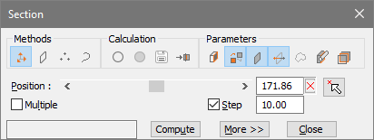
Under Methods, select Section by Direction.
Under Parameters, select Show Cutting Plane, and leave other display options deselected.
Leave the Position options, Multiple, and Step settings at the default values, and click Compute.
Click More, and drag the sliders or type values to change the X and Y orientations of the cutting plane.
Click Compute to create a section entity.
- After you create a section, the result appears in the Model Tree under Models.The default name is “Section [x],” where x indicates the order in which sections are created.You can select, hide, rename, and apply other entity options by right-clicking section entities in the Model Tree.
Note: If you close the Section dialog without clicking Compute, the section is not created and the display reverts to its previous condition. If you leave Section open after clicking Compute, you can select different options and create additional sections.
Options for sections
The options in the Section dialog provide flexibility for the creation of cross-sections. You can specify a different cutting plane and rotate that plane in three-dimensional space. You can customize the way a section appears in the document pane. You can cut with multiple parallel planes. You can limit the parts that are sectioned and export sectioning results as vector image files.
Methods
By default, the method to define the section orientation is set to “Section by direction”. Three of the Methods options in Section controls create planes based on geometric elements that you select.
Section by direction
cutting plane is normal to the active axis of the Main CS.
Note: You can reassign the Main CS, active axis, and define new coordinates systems while the Section controls window is open.
Section by plane
 aligns the cutting plane along one of the selected planes in the geometry.
Section by 3 points
 defines the cutting plane by three points that you click in the 3D display.
Section Along a curve
 Aligns the cutting plane along a curve that you select in the geometry.
Look for instructions in the text area to the left of the Compute button. Text appears here when the method you select requires further actions.
Calculation
Geometrical Section
 Calculates based on exact geometry, if read from the CAD file. When not selected, sections are calculated using display information (tessellation).
Create Face
 (Available only when Geometrical Section is selected) Calculates the face corresponding to the section. The results are used to calculate the section area in Physical Properties.
- DXF Export
 Exports the section to a vector image file that can be used for documentation.
 Note: When Multiple is selected, each calculated section is saved in a separate file. The filenames include the text typed in File Name and a number corresponding to the number of the section.
- DXF Export
Add in configuration
 Makes it possible to reinstate all conditions that existed when you created the section. For example, this option retrieves the orientation, part positions, default view, and so forth. You can add sections to locked or unlocked configurations.
Parameters
Show capping faces
 Displays surfaces covering the cut sides of parts. Capping faces appear in Shading mode with no edge, using the part color.
Use part color for curves color
 Toggles the coloring of the intersection between parts and the cutting plane. When deselected, these intersection lines appear in yellow.
Show Cutting Plane
 Displays an outline of the cutting plane with a solid arrow indicating the axis normal to the plane.
When the cutting plane is shown, it appears with an arrow and dots at the end of the axes lines. You can drag the arrow or dots to move and rotate the cutting plane.
Displays an outline of the cutting plane with a solid arrow indicating the axis normal to the plane.
When the cutting plane is shown, it appears with an arrow and dots at the end of the axes lines. You can drag the arrow or dots to move and rotate the cutting plane.Flip Cut Side
 Reverses the visibility of sectioned parts from one side of the cutting plane to the other.
Show Only Section Curves
 Hides the parts and outlines the intersections between the cutting plane and the sectioned parts.
Cut Only Selected Parts
 Restricts the sectioning to cut only the parts you select in the document pane or Model Tree.
Show Parts Completely
 When selected, the entire parts remain visible, and highlight lines show where the plane cuts through them.
When deselected, the section appears in a tear-away view (with everything on one side of the cutting plane hidden).
Position
Position slider and value box Moves the cutting plane.
Reset Value
 Restores the cutting plane position to the default value.
Select Point To Put Section Plane
 Moves the designated section plane parallel to itself to the position of the selected point.
Multiple Creates sections using multiple parallel cutting planes. Note: You can see the sections after you click Compute. The Multiple option doesn’t include a preview.
Nb Sections option and value (Appears only when Multiple is selected.) Activates the box that you can edit to set the number of cutting planes. When not selected, the number appears in the value box but can’t be edited. Step value Has two effects. First, it adjusts the effect of clicking the Position slider arrows. Larger Step values move the slider more. Second, when Multiple is selected, Step determines the distance between the cutting planes.
More options
Clicking the More button expands the Section controls window. The button is not available for the Section Along a Curve method.
Tilt Y slider and value box Rotates the cutting plane around the Y axis of the Main CS. Tilt Z slider and value box Rotates the cutting plane around the Z axis of the Main CS.
Align the camera to a section
The set camera feature arranges the 3D display according to your choice of elements. You can use this feature to adjust the view in relationship to section entities.
In the Model Tree, select the Section #x folder.
Click
 in HOME tab and then
  and select From Selection.
Clipping
Clipping (or double-clipping) is a view created by two planes cutting across parts. The clipped portions lying between the two planes are visible and other portions are hidden. Clipping doesn’t create entities, so nothing new appears in the Model Tree after a clipping operation. Clipped views are associated with the active configuration at the time they are created. You can toggle the clipped view off and on when its associated configuration is active. This mode helps and facilitates the understanding and the manipulation of complex assemblies.
Creating a clipped view
Click
 in VISUALIZATION tab
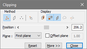
Select the method for orienting the first plane, and select geometries, as needed.
Drag the Position slider or type a value for the plane displacement.
In Plane, choose Second Plane, and select a method and position. Select from the same options and controls as for the First Plane.
Choose Display options, as needed.
(Optional) Select Offset Plane and enter a value for the offset.
7. (Optional) Click More and drag the orientation sliders to rotate the clipping plane around the Y and Z axes.
Clipping Methods and Display options
Clipping and Sections include similar options for defining and positioning cutting planes. The Display options for the two features are also similar.
Methods options
Clipping by direction
Aligns the cutting plane normal to the active axis of the Main CS.
Note: You can reassign the Main CS, active axis, and define new coordinates systems while the Section controls window is open.Clipping by plane
Aligns the cutting plane along one of the existing planes in the geometry.Clipping by 3 points
Defines the cutting plane by three points that you click in the 3D display.Select point to put plane
 Moves a defined section plane at the selected point, parallel to its original position.
Display options
Show capping faces
Displays surfaces covering the cut sides of parts. Capping faces appear in Shading mode with no edge, using the part color.Use default curves color or use part color
Toggles the coloring of the intersection between parts and the cutting plane. When deselected, these lines appear in yellow.Display clipping
plane Displays an outline of the cutting plane with a solid arrow indicating the axis normal to the plane.Display curves
Outlines the intersections between the cutting plane and the clipped parts.Flip clip side
Reverses the visibility of clipped parts from one side of the cutting plane to the other.
Show, hide, or edit a clipped view
Click in
in VISUALIZATION tab.
Note: When you reopen a clipped view, the Clipping controls window opens. You can close it to leave the clipping display the way it is. Or, you can change and apply different clipping options.
Comparing and splitting parts
Comparing parts
The Compare feature identifies geometric differences between two parts within a document. You can compare two different parts or two versions of the same part. The results appear in the document pane and in the Model Tree.
Note: This feature works when B-rep is selected as the Reading Mode preference.
Click
 in DESIGN REVIEW tab, the following dialog box appears:
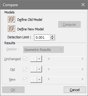
Select Define Old Model, and then select a part in the Model Tree or document pane.
Select Define New Model, and select a second part.
As needed, change the value for Detection Limit, and then click Compute.
Note: The Detection Limit sets the tolerance threshold for the comparison. Differences under the specified value aren’t identified as modifications of the part.
5. Select a Display menu option and colors, and drag transparency sliders for the display of results, as needed. When you click OK, a new entity, Compare #x, appears under the Models structure of the Models Tree.
Note: The actual results of a Compare Parts computation are based on precise geometry. The Representation Results also calculates based on exact geometry, but they are shown in tessellated form. Viewing Representation Results is useful because you can easily identify which areas changed and how they changed.
Results options for part comparisons
Display indicates how the calculated results are shown.
Geometric Results Calculated from exact geometry.
Representation Results Calculated from the currently active level of detail for the display.
Unchanged Area common to both parts.
Old Area unique to the first component part.
New T Area unique to the second component part.
Check boxes Set the visibility the Unchanged, Old, and New spaces. Selected items are shown. Deselected items are hidden.
Color swatches Open color pickers for designating the Unchanged, Old, and New spaces.
Sliders Change the transparency of the Unchanged, Old, and New spaces.
Splitting parts
Splitting parts is a function dedicated to mold preparation for manufacturing parts. In Tetra4D Reviewer, you can split parts in your choice of directions and analyze draft angles for a specific split. You can make sequential splits in various directions. After splitting, different colors apply to parts on either side of a split. Each split is an entity that appears as a Split #x folder under Models in the Model Tree. Splitting is available only for files read with B-rep mode, selected in the reading mode preferences.
Splitting a part
Click
 in DESIGN REVIEW tab
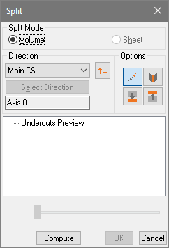
Select Volume or Sheet as the Split Mode.
Choose a direction for the splitting axis, and then select the reference items in the display.
Note: An Accept/Reject
pointer icon appears when the position you click could mean
various things, such as a point, edge, or surface. Use the right and left mouse buttons to
step through the possible selections.As needed, select Inverse Direction
 , and any buttons in the Options area that you want to apply.
Note: Before you finalize the split, you can check your settings by right-clicking undercut preview and choosing draft angle analysis.
Click Compute.
(Optional) Change Split options, and click Compute again to create more splits.
Click OK to create the splits, or click Cancel to close the controls without creating the split.
Split options
Parting Mode
Volume The default setting.
Sheet Processes parting in only one direction. Optimizes results for splitting parts without any thickness. (Available only for shell-based surfaces.)
Direction
Main CS Aligns the splitting axis to the active coordinates system. (No selection required.)
2 Points Aligns the splitting axis to points that you designate. Edge Aligns the splitting axis to an edge of a designated part. Plane Aligns the splitting axis to a designated flat surface.
Inverse Direction
Select Direction Restarts the process. Click Select Direction when you want to change your selection of two points, an edge, or a plane.
Note: The text under Select Direction describes the currently set splitting axis.
Options
Part in active and opposite directions
 Determines two groups of faces instead of just one group.
Split faces with their silhouette curves
 When available, splits any non-planar face into two faces according to the splitting direction. Also, useful for some non-planar faces that are partially visible from both sides of the splitting direction. The determined subfaces are automatically linked to the appropriate group.
Add vertical faces to bottom group
 Attaches non-assigned faces to the bottom group. Available only when Inverse Direction is deselected.
Add vertical faces to upper group
 Attaches non-assigned faces to the upper group. Available only when inverse Direction is selected.
Slider
Move groups along directions (Visual aid, available after a split computation.) Moves the split entities from their original positions, following the direction of the splitting axis.
Reading Split results
The results of a split appear immediately in the Split controls window and in the Model. If you close the Split window and reopen it later, the results of the original split don’t appear there. The results remain in the Model Tree. The organization of information is similar in both places.
Note: Be careful to leave the Split controls window open if you want to see a separation display. The slider in the Draft Angle Analysis dialog box creates this view.
Unassigned Faces remaining stores all faces that were undetermined during the split operation.
Split #[x] (In the Model Tree only.) Entity representing the splitting session. Groups, Unassigned Faces, and Parted Faces listings are nested under the Split.
Group #[x] The splitting session listings. If you compute multiple splits simultaneously, then multiple Group # items appear, each with a unique value for x.
Parted Faces #[x] The faces that are assigned during a splitting operation. A single split produce either one or two Parted Faces groups, corresponding to the number of directions selected. Parted Faces are nested under the Group #.
Position slider Moves the display of separated parts along the splitting axis.
Note: Right-clicking an item in the results area opens a context menu. The options available depend on the item clicked.
Note: You can hide or show individual groups from a split like any other entity. The Hide and Show commands appear on the context menu that opens when you right-click the group in either the Split window or Model Tree.
Analyzing draft angles
You can analyze draft angles during the splitting process, either before or after you compute the split. Draft angle analysis is useful for testing directions before you finalize a split.
Note: After you close the Split controls window, draft angle analysis is not available.
In the Split controls window, choose Draft Angle Analysis on a context menu:
Before making a split, right-click Undercuts Preview in the results area.
After making a split, right-click Group #x in the results area.
Adjust settings and selections, as needed:
Click the color swatches to open color palettes, and select preset or custom colors.
Change the values for the angles taken according to the split directions. The angle values become threshold values for the colors display.
View the effects of your changes:
Click Show Undercuts.
Drag the slider to move the separated parts along the splitting axis. (Available only for computed splits, not for Undercuts Preview.)
Note: If you make further adjustments to the colors and values, click Show undercuts to toggle back to the original view. Then click Show undercuts again to update the view.
Close the Draft Angle Analysis dialog box:
Click back to split to return to the split controls window to finalize the split or change the settings for the split.
Click OK or Cancel to close the dialog box and return to the document window without finalizing the split.
Reassign split faces
You can change the assignment of faces only immediately after the split, while the Split controls window is still open.
Before you begin, drag the slider in the Split controls window to visually separate the various unassigned and assigned group displays.
With Split controls still open, select faces:
To change an entire group of faces, select the group in the results area.
To change individual faces, click or Ctrl-click in the document pane to select faces in the groups.
Choose from the context menu:
Right-click a group in the Split controls window and choose Part With.
Right-click the selection in the document pane and choose Part With.
In the document pane, click any part in the group to which you want to assign the selection.
Unassign individual split faces
In document pane, click or Ctrl-click to select individual assigned faces.
Right-click the selected faces and choose Unassign.