
Managing entities and views
For Tetra4D Reviewer, the word “entity” refers to various kinds of information. Some entities are read from the CAD data, like physical parts, annotations, and PMI information. The entities read from the original CAD file flow into a hierarchical list in the Model Tree. Views combines the visibility of the 3D objects with camera definition, zoom level, and other factors. Views can be saved as configurations.
Entities in 3D documents
The Model Tree positions entities under categories, according to their type. For example, markups and measurements that you create in sessions appear under Annotations. Items read from the CAD file, such as the component parts of an assembly and CAD PMI, appear under Models. The appearances of the icons in the Model Tree give clues about entity status. Colored icons represent entities that are visible in the document pane. Dimmed icons represent hidden entities. A small funnel on a dimmed icon indicates that the entity is hidden because it is on an inactive layer. You can’t create physical parts in Tetra4D Reviewer, but you can create various other types of entities. For example, annotations and bounding boxes are considered entities, but they aren’t physical parts of an assembly. Typically, you create these types of entities during an analysis or publishing workflow. You can also add selected parts from one document to another by importing or ordinary copying and pasting.
Renaming an entity
Right-click the entity in the Model Tree and choose Rename.
Type a name, and press Enter.
Note: You can change entity names by two other methods. You can double-click the name in the Model Tree and type to overwrite the name. Or, you can change it on the General tab of the entity Properties.
Removing entities
You can delete unwanted entities from a document, either temporarily or permanently. All types of entities can be removed. When you delete an entity temporarily, the entity appears in the Model Tree under the Recycle Bin for that document. Markups and dimensions associated with that entity move automatically to the Recycle Bin. You can restore the entity from the Recycle Bin and then restore its associated markups and dimensions. Deleting an entity that is already in the Recycle Bin deletes it permanently. If the deleted entity was a physical component of the product assembly, you can import it again from the original source file, if available.
Note: Instead of removing components from a file, you can hide them. The components remain in the session file and can be easily shown again.
Delete entities from a document
Select the entities that you want to delete.
2. Click Delete button in HOME tab, to remove the entity and store it in the Model Tree Recycle Bin.
Restore deleted entities
Expand the Recycle Bin for the file in the Model Tree panel.
Right-click the entity, and choose Restore.
Selecting entities
About selecting entities
An entity is anything in a 3D model that you can select. Selected entities are activated so that you can change their properties, move them, change their visibility, and more. Tetra4D Reviewer offers advanced selection features, beyond the common clicking techniques. For example, you can select entities that are hidden in the document display.
Select entities manually
To select visible entities in the document pane, click, Ctrl-click, or hold down Shift and drag a selection box around entities.
To select entities in the Model Tree, click, Shift-click, and Ctrl-click to select visible and hidden entities. Ctrl-clicks select non-adjacent entities. Shift-clicks select all adjacent entities within a range. Note: The entities that can be selected in the display area depend on the active Selection Filters.
Selecting entities by attributes
It takes only one step to select all entities that share a trait. For example, you could select all solid entities or all markups. You can also select all the entities in a document in one action.
Selecting all displayed entities
Click
 in DESIGN REVIEW tab.
Selecting entities by type
Click
 in VISUALIZATION tab, and choose the wished type.
Hold down Ctrl and choose another type again to add a second type to the selection.
Note: The types include Point, Wire, Coordinates System, Planes, Surfaces, and Solids. Dimmed items on the By Type submenu indicate that no entities in the current document correspond to that type.
Selecting entities by layer
The list of layers depends on the layers that were read in the files present in the current document.
Click
 in VISUALIZATION tab.
2. In the Select a Layer dialog box, select a layer or Ctrl-click to select more than one layer. When you close the dialog box, entities on the selected layers are selected.
Note: The layers that have been created in the CAD application appear in Tetra4D Reviewer session files only if the import options are set to address them.
Selecting entities by color
Use this method to select components that have the same color property.
Click
 in VISUALIZATION tab.
Note: The Select a Color dialog box shows all the colors in use in the document.
Click User Selection to activate the selection process.
Select colors:
Select a part in the document pane to select all parts of that color.
Select the name of a color in the dialog box to select all parts of that color.
Select one color in the dialog box and Shift-click another color name to select all parts of all colors in the range.
Ctrl-click to select multiple color names or multiple parts.
Note: To restart the selection process, click User Selection twice.
Selecting entities by Attribute value
Click
 in VISUALIZATION tab.
Select an attribute in the Attribute list or type the attribute name in the box below the list to jump to that attribute.
Select an item in the Attributes list.
Type the name of an attribute in the box below the list.
In the Values pane, select a value for that attribute or type the value name to jump to that value.
Click Select.
Selecting an entity by a search
You can use the Find feature to search for some kinds of entities, such as physical parts and assemblies, balloons, and annotations.
Click
 in VISUALIZATION tab.
In Find What, type part or the full name for the entity.
Select any options you want to apply to the search:
Match Whole Word Only: Ignores occurrences within longer words.
Ignore Hidden: Ignores entities that are hidden.
Match Case: Ignores occurrences with different capitalization of text.
Ignore Unloaded: Ignores instances that appear in the Model Tree but that are not currently loaded.
Click Find Next or Find All. Found entities are automatically selected.
Note: You can search for CAD-read Product Views and 3D PMIs. The Find feature ignores configuration names, animation actions, and bills of material.
Changing a current entity selection
After you select multiple entities by any process, you can change that selection. You can manually change the selection status of individual entities. You can deselect all entities. You can also switch the status of all visible entities in one step. This action automatically selects all previously unselected entities and deselects all entities that had been selected.
Editing an entity selection
1. In the document pane or the Model Tree, Ctrl-click each entity that you want to select or deselect.
Deselecting entities
Click
 in DESIGN REVIEW tab.
 You can also cancel all selections by clicking an empty area of the document pane.
Toggling the selected entities
Click
 in DESIGN REVIEW tab.
Note: This inversion of selection is independent of the selection filters. Toggling reverses the selection status of all visible entities. Hidden entities are not affected.
Entity properties
About entity properties
The Properties dialog box contains information about a selected entity or entities. The information comes from one of two sources: the original CAD design file or default information applied by Tetra4D Reviewer. CAD information always takes priority over default information. Some of the information in the Properties dialog box is read only. Non-interactive information appears with a gray background. You can change some Properties information for entities. The changes you apply to the selected entities is saved with the session file. A related dialog box, Physical Properties, has a different function from the Properties dialog box. For example, Physical Properties includes features for making calculations of area, volume, and mass. These calculations are based on information in the Properties dialog box.
Viewing and editing entity properties
Properties dialog boxes are available for all types of entities. You can change some entity properties. Most of the editable properties are accessible in the Color/Material tab. Properties that are dimmed in the dialog box can’t be edited.
In the Model Tree or document pane, select the entity.
Click
 in DESIGN REVIEW tab.
Change the properties on each of the four tabs, as needed.
Click Apply to apply the change to the entities without closing the Properties and examine the entity appearance in the document pane.
Continue adjusting settings, as needed.
When you finish, either close the Properties or click Apply and select the next entity that you want to edit.
Note: Configurations, Coordinate Systems, and the file itself do not have Properties dialog boxes. You can open an information display for the file itself by right-clicking the file in the Model Tree and choosing Document Information.
Adding and deleting user-defined materials
Tetra4D Reviewer includes several default material definitions, such as Aluminum, Copper, and Steel. Each material definition incorporates specific density, color qualities, and transparency settings. When you apply a Material option to an entity, the entity assumes all of the material characteristics. You can define, save, and apply custom materials. These user-defined materials appear on the Properties dialog box Material menu and are saved with the session file. After you apply a material, you can adjust the settings for that entity. Those changes apply only to the selected entity and do not alter the saved definition for the material. If you want to change the material definition, define a new material with the settings you want and delete the old material.
The attributes you choose apply only to the selected entities. If you want to make this set of attributes
available for future use, create a user-defined material before you close the dialog box. User-defined
materials are saved with the session file.
Adding a user-defined material
Select an entity, and click
in DESIGN REVIEW tab, and select the Color/Material tab.Specify the Colors, Transparency, and Density settings for the material.
Choose User Defined for Material and click the plus sign.
Type a name for the custom material in the Material Name dialog box, and click OK.
Deleting a user-defined material
In the Material pop-up menu on the Color/Material tab, choose the user-defined material that you want to delete.
Click the minus sign.
Note: The minus sign button is not available for the default materials because they can’t be deleted.
Edit a user-defined material
Once you create a user-defined material, its properties are permanent and can’t be edited. However, you can easily define a new material based on the existing material properties.
Select a part and click
in DESIGN REVIEW tab.On the Color/Material tab, select the Material definition that you want to replace, and change the settings, as needed.
Click the plus sign, type a name to define the new material, and click OK.
Note: Reusing the name of an existing user-defined material does not overwrite it or alter its settings. Both instances of the name appear on the Material menu until you individually delete them.
In Material, select the user-defined material that is now obsolete, and click the minus sign to delete it.
Properties options
Four tabs organize the Properties information. Some contain read-only information and some include interactive options.
General tab
Name: Name of the item, as shown in the Models structure.
Text area: Descriptions of attributes, if any exist. Look here for information about geometric characteristics and the number of faces, for example.
Color/Material tab
Material: Options for predefined and user-defined substances, such as copper, steel, and aluminum.
Simple Color: Limits the available color options to Diffuse.
Material Colors: Makes options available for individual Diffuse, Ambient, Emissive, and Specular colors and for Shininess.
Transparency: Sets the opacity of the selected entity. Lower percentages produce more transparent views of the entity. At 0% Transparency, the entity is invisible.
Density Sets: the physical property for the selected material, using the specified units of weight and volume.
Position tab
Matrix: Indicates the translation and rotation information for each axis (Tx, Ty, Tz, and Rx, Ry, and Rz in relation to the Tx, Ty, and Tz values).
Sx, Sy, and Sz: Indicated the values of scaling.
Restore: Resets position options.
Is Mirror: Indicates if a symmetry is applied to the entity.
Is Unit: Indicates if transformations are applied on the entity.
Source tab
The Source tab provides information related to the original CAD file. The tab lists the original filename, the design application used to create the file, and the units of measurements.
Changing appearances of entities
Hiding and showing entities
You can change hide or show any individual entities in the document pane. Visibility does not affect the structure of the Model Tree. The Model Tree icons for hidden (invisible) entities become light- gray. Icons for visible entities are gray. You can change the appearance of entities in several ways:
Altering visibility by hiding and showing selected entities.
Adjusting the transparency of selected objects.
Setting an object to phantom mode.
Isolating an entity
Isolating will hide all unselected objects so that only the selected ones remain visible.
Select the entities that you want to isolate.
Click
 in HOME tab.
Hiding or showing individual entities
Select the entities that you want to hide or show.
Click
 in HOME tab.
 in HOME tab.
Displaying all entities
Click
 in HOME tab.
Hiding or showing all annotations by type
Session annotations are 3D markups and dimensions you create in Tetra4D Reviewer. The context menu Hide/Show command changes the visibility of annotations.
Click
 in VISUALIZATION tab to hide all PMI markups.
2. Click  in VISUALIZATION tab, to hide all dimensions and markups created in Tetra4D
Reviewer.
in VISUALIZATION tab, to hide all dimensions and markups created in Tetra4D
Reviewer.
Note: Individually hidden 3D PMIs are dimmed in the data tree. When you choose Hide 3D PMI, the PMI markup icons aren’t dimmed even though the markups aren’t visible.
Changing the transparency of entities
Changing transparency adjusts the opacity of an entity so that you can see it and see through it. You can change transparency temporarily, to get a quick glance at the underlying parts or to do other work. Temporarily transparent objects aren’t selectable. You can also change the Transparency property. This type of transparency leaves the entity selectable. The entity remains semi-visible until you actively reverse the transparency setting. Phantom mode applies a preset level of transparency to the selected entity. You can’t select an entity that is in Phantom mode.
Note: Phantom mode is a different type of transparency: It is persistent until you actively reverse it and the objects are unselectable.
Select the entities.
Click
in DESIGN REVIEW tab.On the Color/Material tab, drag the Transparency slider or enter a value for the percentage of transparency.
As needed, click Apply and repeat the preceding steps to set other entities at a different percentage of transparency.
Click OK to apply the changes and close the Properties dialog box.
Apply transparency temporarily
This technique applies transparency without requiring you to select entities first. While a part is temporarily transparent, it is unselectable. However, you can select other parts, take dimensions, and do other work without reversing the temporary transparency.
Move the pointer over the part that you want to make transparent.
Press H key.
As needed, press H again to make more parts transparent temporarily.
te:** You reverse temporary transparency actions one step at a time by pressing S.
4. Click anywhere in the background to remove the temporary transparency and restore selectability.
Phantom mode
In Phantom mode, selected parts appear semi-transparent and can’t be selected. You can apply this mode to any geometric entity.
Displaying entities in Phantom mode
Select the parts in the Model Tree or document pane.
Click
 in HOME tab.
Note: The phantom mode remains in effect until you choose View > Phantom again to exit Phantom mode.
Adding and removing entities from Phantom mode
Click
in HOME tab.Change the selection, as needed:
Ctrl-click to add or remove parts from the current selection.
Click outside the current selection to deselect, and then make a new selection.
Click
in HOME tab.
When adding entities to a set of entities that are already displayed in phantom mode,
select those entities first. Then choose View > Phantom twice or click the Phantom toolbar
button twice. These actions reapply the phantom mode to both the already displayed
in phantom mode entities and to the ones you selected later.
Changing the display mode
1. Click  in VISUALIZATION tab and select the rendering mode among the 4 following
renderings:
in VISUALIZATION tab and select the rendering mode among the 4 following
renderings:
Solid: Click
 in VISUALIZATION tab, shades in the entire surface area of the parts.
Solid outline: Click
 in VISUALIZATION tab, shades in the entire surface area of the parts and outlines the edges of the parts.
Wireframe: Click
 in VISUALIZATION tab, outlines the edges of the parts.
Illustration: Click
 in VISUALIZATION tab, shows the entire surface area of the parts in flat white and outlines the edges of the parts.
Perspective
1. Click  in VISUALIZATION tab, adjusts Solid, Wireframe, or Illustration mode so that the
geometry resembles a physical view.
in VISUALIZATION tab, adjusts Solid, Wireframe, or Illustration mode so that the
geometry resembles a physical view.
Accessing the PMIs
The Product Manufacturing Instructions (PMIs) read from CAD files can be numerous and of various types. PMIs are often associated with Product Views read from the CAD files. Product Views appear in a folder under Models in the Model Tree. Product Views are like Configurations that you define and save in Tetra4D Reviewer. A Product View sets the orientation, zoom level, and visibility of the 3D objects and 3D PMI markups. Views created in CAD can also be associated with the 2D environment, as views defined in a drawing.
Activating a PMI Product View
Click
 in VISUALIZATION tab opens the following dialog:
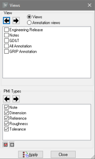
Select Views or Annotation Views (if available).
Under PMI Types, select the types of PMI markups you want to show: Notes and References (if available).
Under View, select the view you want to see:
Click the arrows to step through the list, which automatically applies each Product View as you progress.
Click a check box to select a view, and click Apply.
Close the Views window.
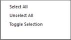
Note: You can select or deselect all PMI Types with the Select All
 and Unselect All
  buttons.
Moving parts and assemblies
About moving components
You can change the positions of individual parts and assemblies in the document. This feature is especially useful if parts from different source files appear superimposed at the same location. The new positions are associated with the currently active configuration. When you switch to a different configuration, moved parts appear in their original positions. When you reactivate the configuration with the moved parts, they jump back into their moved locations. Note: You can move all parts simultaneously in different directions by creating an exploded view. Exploded views can also be saved as part of a configuration.
Activating the “Drag and Drop” displacement control
If a locked configuration is active, switch to an unlocked one or create a new configuration.
Select the parts to be moved.
Click
 in DOCUMENTATION tab.
Note: The displacement manipulator appears around the selected parts.
Use the manipulator to move the parts as described below.
Moving parts freely with direct displacement controls
Click the yellow dot that appears in the center of the manipulator.
2. Without pressing the mouse button, slide the manipulator to move the selected parts in any direction. 3. Click once to release the parts in this new position.
Moving parts along axes
Click one axis of the manipulator.
Without pressing the mouse button, slide the manipulator along the direction of the arrow.
Note: As you slide the pointer, a small box displays the value of the displacement along the axis.
Click once to release the parts in this new position.
As needed, continue to move and rotate the parts using the other activated controls.
Rotating parts along axes
Click one rotation arrow of the manipulator.
Without pressing the mouse button, slide the pointer around within the visible circle to rotate the part.
Note: As you slide the pointer, a small box displays the angle (in degrees) between the original position and the rotated position.
Click once to release the parts at the rotated position.
As needed, continue to move and rotate the parts using the other activated controls.
Moving parts with the Move feature
You can define displacements through several methods available in the Move controls window. The Move feature is available only when an unlocked configuration is active.
As you work with the Move feature, notice the text area near the bottom of the window. This area displays context-sensitive information about actions that are required as you complete steps in the process.
If necessary, activate a new or an existing unlocked configuration.
Click
 in DOCUMENTATION tab to activate the feature
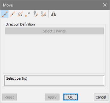
Select a method at the top of the Move controls dialog.
In the Direction Definition area, select a Method if available: Main CS, 2 Points, Edge, or Plane.
Drag the Displacement slider or type a value to set the displacement value
Note: If you aren’t satisfied with your selections, click Reset to start over from the original position.
When you are satisfied with the position change, continue working:
Click Apply to save the results, and continue to move other parts.
Click OK to save the results and close the Move controls window.
Methods to move parts
Move from point to point 
Moves the parts along a direction that you define by clicking two reference points in the document pane.
Move along axis 
Moves the parts along an axis defined for the selected Method option.
Rotate around axis 
Moves the parts along an axis defined for the selected Method option.
Move from axis to axis 
Moves the parts in relation to your selection of an initial coordinates axis system and a target coordinates system axis.
Move with coordinates 
Moves the parts according to the x, y, and z coordinates that you specify.
Rotate with angles 
Moves the parts according to angles you specify to the x, y, and z axes.
Mirror 
Creates a mirror-image copy of the selected part, naming the new version “SYM [part name].” The part appears on the opposite side of a symmetry plane that you define.
Methods to define a displacement direction
The Method menu is available for Move Along Axis and Rotate Around Axis. The menu also appears for Mirror, but only Main CS and Plane are listed.
Main CS
Moves along the active axis of the designated Main CS.
2 Points
Sets the direction by two points that you select in the document pane. The Accept/Reject
 pointer appears as you select points so that you can confirm the position or toggle to another possible location.
Edge
Sets the direction parallel to an edge that you select in the document pane.
Plane
Sets the direction along a plane that you select in the document pane.
Note: Clicking Select Direction cancels any previous reference items and restarts the process of setting a direction.
Stack up displacements for multiple parts
Stack Up option will simultaneously move multiple parts by different amounts of displacement. The order in which you select the parts determines how far they move. For example, if the first part moves by x amount, the second part moves 2x, the third part moves 3x, and so on.
Click
in DOCUMENTATION tab.Select a type of action, action options, and displacement, as usual.
Note
Stack Up is available only for move along axis, rotate around axis, rotate with angles, and Move with coordinates.
Select
 Stack Up.
Ctrl-click to select parts, selecting the part you want to move least first. Continue selecting in order of increasing multiples of the displacement.
Set the displacement value, and click Apply or OK.
Note: The Stack Up feature is also available for custom animations.
Restore the initial positions of moved parts
After you move one or more parts, you can restore them individually to their previous positions.
Note: If you locked the configuration after moving the part, unlock it. When it is unlocked, you can restore parts to earlier positions.
Select the moved parts.
Click
 in DOCUMENTATION tab.
When a message appears asking you to confirm the repositioning, click OK.
Note: If you have moved a part several times, you can only restore the most recent previous position.
Locate entities visually
Complex assembly displays can make it challenging to locate specific parts and other entities, such as markups and balloons. One method of identifying an entity is to select it. Selecting highlights entities in both the document pane and the Model Tree. Another method is to use the Focus and Show Me features. These features are especially useful when you want to locate an object without selecting it. You can also locate an entity by searching it.
Show me (Highlight an entity)
Highlighting draws a red, translucent sphere around the image of the selected entities in the document pane.
1. In the Model Tree, right-click the entity and choose Show Me. Clicking anywhere in the document pane removes the highlight.
Focus on an entity
Focusing does two things: It adjusts the zoom level to the maximum level at which you see all selected entities. It places the center of rotation to correspond with the center of a bounding box for the selected entities.
In the Model Tree or document pane, select one or more entities.
Right-click a selected entity and choose Focus.
Note: The zoom level and center of rotation set by focusing remain in effect until you change them.
Creating geometric entities
You can generate some simple entities based on existing geometry. For example, you can create a reference point, an intersection, or an axis, or define a new coordinate system. These entities are permanent and appear in the Model Tree. The location of the entity in the Model Tree and the type of icon appearing with it depend on the entity type. You can use these entities for other operations, such as measuring. Note: Created entities are not solids or components in the 3D assembly. Physical parts and assembly entities must be created in a CAD application and can be imported into a session file.
Creating an entity
Click
 in DESIGN REVIEW tab.
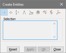
Select the type of entity that you want to create.
Follow the cues that appear displayed in the status bar at the bottom of the application window to make selections in the document pane.
Create the entity:
Click Apply to create the entity and leave Create Entities open.
Click OK to create the entity and close Create Entities.
Click Close to close Create Entities without creating an entity.
Reset to deselect and start creating a different entity.
Types of created entities
The Create Entities control window provides tools for creating nine types of entities. These entities
are geometrics.
In the same way as with measurement tools, several Create Entities tools ask you to confirm the
locations you select. The pointer changes to the Accept/Reject pointer, indicating that you can
right-click to reject the proposed location and see another proposed location.
 Creating a point from selection
Creates a Point entity at a position you select after selecting this tool.
 Creating a point as a center of a circle defined by 3 points
Creates a Point entity from three points you select in the document display after selecting this tool.
 Creating a point by coordinates
Creates a point from the values you type in X, Y, and Z, using the CAD coordinates system.
 Creating a point as an intersection of segments
Creates a point where two selected line segments cross.
 Creating a point as an intersection of a face and a segment
Creates a point where a selected line segment crosses a selected face.
 Creating an axis from a cylinder
Creates a wireframe entity from the axis of a cylindrical part or entity.
 Creating a curve as an intersection of faces
Creates intersecting curves from faces that you select.
 Creating an entity by extraction
Retrieves information from the selected items as entities under an entity named “[PARTNAME] Extraction.” Extracted entities can be based on any combination of the three Selection options:
Basis Surface: Generates the original surface for the selected face of the solid or the surface as it was before any trimming operations.
Face: Generates a copy of the selected face from the solid or the surface.
Wire: Generates subcurves and characteristic points from a selection of composite curves. Generates original and characteristic curves for a selected face. Original curves refer to trimming curves. Characteristic curves refer to elements such as the axis of a cylinder.
 Creating a Coordinate System
Defines a system of coordinates based the selected reference option and elements you select in the document pane. The new coordinates system appears as Axis [#] under the Coordinates System section of the Model Tree.
Options for creating coordinates systems
Normal to surface
Sets the origin at the point you click. Sets the Z axis normal to the surface at the origin. The orientation of X and Y axes are set automatically in relation to iso-curves of the surface, and can’t be edited.
Points
- Sets the origin at the first point you click. Your second click sets the X axis. Your third click defines the Y axis and XOY plane.
Note: The vector defined by the points 2 and 3 isn’t necessarily perpendicular to the first vector defined by points 1 and 2.
2 Edges
- Sets the origin at the intersection of the two edges. The first edge you select sets the X axis. The second edge defines the XOY plane.
Note: The two selected edges aren’t required to be perpendicular, but they must be linear, nonparallel, and secant.
Curve + Point
- The first point clicked sets the origin and the Z axis. The second click sets the X axis.
Note: Cylinder parts present a special case for the Curve + Point method. Selecting the cylinder sets the cylinder axis as the Z axis. The second click sets the position of the origin and the direction of the X axis.
From CS
Creates a copy of the selected coordinates system.
Naming rule for created entities
Tetra4D Reviewer assigns default names to created entities. The default name varies with the type of entity created. Some names include a number that indicates the order in which it was created. Numbers in parentheses following the entity name indicate how many individual entities are included in the created item. Different created entities can have identical names. You can rename entities to make it easier to tell them apart, as needed.
Operating with the model in the 3D window
About 3D controls in the 3D window for the document
You adjust the visualization of the 3D entities using 3D Control tools, which are accessible in the HOME tab. The selected 3D tool determines what happens when you drag the mouse within the 3D window.
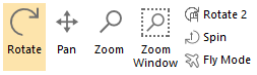
Rotate the 3D model
This control rotates the model around a specific point in the 3D window. The Rotate tool is active by default.
Click
 in HOME tab.
In the document pane, set the center of rotation:
Drag from any position in the background to rotate around the center of a bounding box that encloses all visible parts.
Drag from a position on a component to rotate around that starting point, as indicated by a crosshair
 that appears.
Lock a rotation axis
By default, the rotation can be performed freely around any axes.
Click
in HOME tab.Using the right mouse button, start dragging to rotate the 3D objects.
As you drag, press the spacebar repeatedly to lock a specific axis:
One time Locks the X axis.
Two times Locks the Y axis.
Three times Locks the Z axis.
Four times Unlocks all axes so that you can rotate freely around any axis.
A double arrowhead in the View CS display in the lower left corner of the document pane appears as a reminder of the locked axis. The axis remains locked after you stop dragging, even if you activate a 3D Controls tool.
You unlock all axes by repeating this process, pressing the spacebar until no axis has a double arrowhead.
Set a fixed center point for rotating and spinning
By default, the center of rotation is automatically set as the center point of the bounding box calculated including all the visible entities. You can set a different center of rotation that does not change as you manipulate the view in different ways. You can set a fixed center of rotation at any position on any part but not on the background or in empty space between parts.
Click
 in HOME tab.
Note: The Rotation Center tool is available only when one of the Rotate tool or Spin tool is active.
Click a point on one visible part that you want to serve as the center of rotation.
Note: A white crosshair marks the position in the display, even if you switch to a different type of tool.
Drag to spin or rotate the 3D object.
Note: Notice that the Rotation Center tool remains active as you work, even if you switch back and forth to the r 3D Controls tools.
Push
again to cancel the fixed center.
Spin a 3D model
Spinning rotates in relation to the Z axis of the View CS. It is especially appropriate for turning images set on a fixed horizontal plane, such as buildings.
Click
 in HOME tab.
Drag in the document pane.
Pan horizontally and vertically
Panning changes the position of the 3D objects in the 3D window while keeping the orientation.
Click
 in HOME tab.
Drag the 3D object left, right, up, or down.
Zoom in and zoom out
Zooming in enlarges or shrinks the view in the document pane.
Zoom in or out
Click
 in HOME tab.
In the document display, drag up to zoom in and drag down to zoom out.
Note: Clicking the Zoom tool and dragging horizontally do not change the zoom level.
If your mouse has a wheel button, you can zoom without selecting the Zoom tool. Instead, turn the wheel forward and backward to change the zoom level. Wheel-button zooming centers around the current pointer position in the document pane.
Zoom window
Click
 in HOME tab.
In the document display, draw a rectangle to define the zoom area.
You can switch temporarily to the Zoom Window tool by holding down Shift and dragging. When you stop dragging and release the Shift key, the previously active tool is reinstated.
Fit the 3D model into the display
The Fit Visible feature shows the model at the maximum magnification that keeps all visible components in the document pane window.
Click
 in HOME tab.
Double-clicking the document display with any tool also changes the view to Fit Visible. In some contexts, you can right-click and choose Fit Visible to show all visible parts.
Activating document views
Tetra4D Reviewer offers several features to change views.
Default views Align 3D objects in various orientations to the axes of the active view coordinates system (View CS).
Camera Aligns the view in relation to a selected element in the geometry. Configurations bear a similarity to default views in that they quickly shift the view. You can create custom configurations, lock or unlock them, and use them in later work sessions.
Set a default view
Applying a default view leaves the zoom level and other viewing characteristics unchanged. The default views appear both on the Views menu and in the Default Views toolbar.
Click
 in HOME tab, and one of the following:
Top, Front, Back, Bottom, Left, or Right: Sets the view normal based on the active View CS.
Iso Sets the 3D objects in a standard isometric view, based on the active View CS.
The Smooth Transitions preferences can help you visualize how the view changes. Selecting these preferences animatesthe3Dobjectsasyouapplybuilt-in views. If these preferences are deselected, the view changes in one step.
Set the camera
A camera setting refers to a combination of zoom level and orientation. Some camera settings are independent entities. Other camera settings change the view according to the entity that is currently selected.
If appropriate, select one or more entities.
Set the appropriate Selection Filters for the type of selection you want to make, such as a curve, face, or axes.
Click
in HOME tab, then click 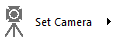 and choose one of the following settings:
From Selection Aligns the view to the currently selected entity or to the next entity that you select.
Restore Config. View Resets the orientation to either the initial settings for the current configuration or the initial view when the file opened.
From Curve/Edge Sets the view perpendicular to the next curve or edge that you select.
From Face Sets the view parallel to the next planar face that you select. Or, if the face is not planar, sets the view normal to the face at the point that you select.
From Coordinate Axis Sets the view perpendicular to an axis (X, Y, or Z) that you select next.
Flip Rotates the view to the opposite side of the assembly or part.
Saving views as configurations
About configurations
A configuration is a view of a 3D model. A configuration includes basic characteristics, such as zoom level, orientation and positions of the 3D objects, visibility of entities, lighting, and background color. Configurations also apply specific types of features created in that configuration. These features include bills of material, balloons, and sections. When you start a Tetra4D Reviewer session or open a new document, the default, Initial Configuration, is active. Unless Initial Configuration is locked, objects open as they appeared at the end of your most recent work session.
Creating a configuration
Adjust the orientation, zoom level, visibility settings, and other characteristics for the view, as needed.
In the Model Tree, right-click Configuration and choose Add Configuration, or click
 in DOCUMENTATION tab.
Type a name for the new configuration.
The saved view becomes the active configuration.
Activating a configuration
In the Model Tree, right-click the configuration and choose Activate Configuration.
You can also use the buttons  and
and  to step through configurations, or just
double-click a configuration in the Model Tree to activate that view.
to step through configurations, or just
double-click a configuration in the Model Tree to activate that view.
Renaming a configuration
In the Model Tree, right-click the configuration and choose Rename.
Type a new name.
Deleting a configuration
In the Model Tree, select the configuration.
Click Delete from the context menu, or press Delete key.
Locking or unlocking an existing configuration
In the Model Tree, right-click the configuration and choose Lock or Unlock.
About locked configurations
When a defined configuration is active and unlocked, any changes to the zoom level, orientation, and so forth, are incorporated into the configuration definition. Locking a configuration prevents changes from altering the configuration definition. Each configuration is individually locked and unlocked. You can lock the default Initial Configuration and custom configurations. You can change the zoom, rotate, hide parts, and make other view adjustments when a locked configuration is active. When you switch to a different configuration and then back to the locked one, the locked configuration appears in its original state. Some features are disabled or can’t be applied to a locked configuration:
Positioning tools
3D Markups
Animation controls
Locking a configuration doesn’t affect your ability to create balloons and bills of material in that configuration.
Hiding and showing entities by layers and filters
Layers and filters are CAD structural features created within certain file formats. When the CAD file is imported into Tetra4D Reviewer, the filters and layers are imported too. You can’t modify the filters and layers in Tetra4D Reviewer. However, you can use them to select parts or to change the view of the 3D objects. The Model Tree for a part on a hidden layer isn’t colored and includes a funnel shape . The icon serves as a reminder that you can’t use the ordinary Hide/Show command to display the part.
Hiding and showing parts by layers
Click
 in VISUALIZATION tab
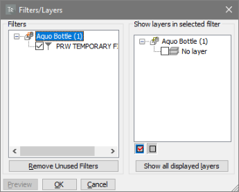
Note: Immediately after the Filters/Layers window opens, you can click Remove Unused Filters to remove the filters that don’t refer to any layer.
Select and deselect layers until only the layers you want to appear are selected, using any combination of methods:
Click the layers check boxes to select and deselect individual layers.
Select Filters in the left pane to select layers associated with that component part or assembly.
Click Select All
to select all layers.Click Unselect All
to deselect all layers.Click Show Layers in Selected Filter to select layers currently displayed in the document pane.
Click Preview, and review the results of your selection in the document pane and Model Tree. If necessary, adjust your layer selections and click Preview again until you are satisfied with the results. Note: The Preview is temporary. If you close the Filters/Layers dialog box without clicking OK, the view resumes its previous condition.
Fly through mode
Activating the Fly through mode
Click
 in HOME tab.
Press and hold the following keys to control Fly Mode direction and speed:
Q and D Move left and right
Z and S Move up and down, left and right (parallel movement without rotation)
A and E Rotate left and right
R and F Forward and backward.
Spacebar Stop movement.
Note: You can also use your mouse to move up, down, right, and left. Use the center mouse wheel to increase and decrease Fly Mode speed.
Release the key to stop the fly through motion. You can also use the mouse wheel to increase and decrease fly through speed.
To see a complete list of keys to use in Fly Mode, open the Preferences dialog box, and click the Fly Through tab. To exit Fly Mode, press ESC or right-click in the model and choose End Fly Mode.
Managing Fly through mode views
With Fly Mode, you can view a model at different angles and magnifications. You can save these views, or positions, to use later. You can also constrain Fly Mode movement to a horizontal plane so that altitude doesn’t change as you move. This feature is useful for moving through architectural models.
Saving a Fly through position
In Fly Mode, position the model as you want to save it.
Right-click the model, and then choose Position > Store Current Position.
Type a name of the position in the dialog box, and click OK.
Modifying a saved position
After you create a position, you can rename it, activate it, or delete it.
Right-click inside the model and choose Position > User Positions.
Select a user position, and then select what you want to do with the position.
Click Close.
Returning to the default position
The default the position in Fly Mode is <Automatic> and always corresponds to the Isometric view.
In Fly Mode, click in the document pane, and then right-click in the model.
Choose Position > Activate Default Position.
Setting a reference plane for Fly through mode
You can set a horizontal reference in Fly Mode to retain the same height as you move through a model. This feature is called walk through mode. Altitude doesn’t change in walk through mode. Note: You can change the default height and reference plane settings on the Fly Through tab of the Preferences dialog box.
In Fly Mode, right-click inside the model.
Choose Reference, and then select the reference type to use:
Plane Uses a horizontal plane as the reference point. The camera position is constrained to the reference plane and the height is specified in the Fly Through preferences.
Main UCS Uses the main coordinate system to define a new reference. When selecting this option, the reference plane is the one that is perpendicular to the active axis (X, Y, or Z). The camera is located at the specified height, which is constant.
Curve or Axis Constrains movement to the length of the curve. The axis is selected automatically by selecting a cylinder face. For an axis or line, you can move anywhere using the keyboard controls (except A and E).
Free Deactivates the previously set reference and restores default Fly Mode behavior.
Invert Direction When Plane of Main UCS is used, Invert Direction changes the orientation of the reference to be opposite the current orientation.
Changing the reference plane
In the Preferences dialog box, click the Fly Through tab.
In the walk-through section, do the following:
To change the height of the horizontal plane, set the height value and corresponding measurement unit.
To hide the reference plane, clear the Display Plane option in the walk-through section.
Restoring the original reference plane
Apply a horizontal reference plane to restore an initial state.
In Fly Mode, click in the document pane and then right-click inside the model.
Note: The model position remains the same, but the direction moves horizontally.
Choose Horizontal from the context menu.
Graphic rotation controls
The graphic rotation controls are displayed in the lower-left corner of the model. Use the graphic controls for quick access to user-defined positions and rotation functions.
In Fly Mode, right-click a part of the model to be the reference point for the rotation. The graphic rotation controls are displayed in the lower-left corner of the model.
Select a control to change the view of the model:
Click the triangle to view a list of user positions, and then select a position from the list.
Click a square to make a 90-degree rotation around the reference point selected in step 1. For example, click the right square to make a 90-degree rotation around the vertical axis to the right. Click the same square again to turn around the model, keeping the same reference point. The back square displays the back view of the model.
Note: The squares are visible only when the mouse is over a model part when you right- click. The point at which you right- click is used as the center of the rotation.
Defining a target point for Fly through
In a complex assembly, defining a target point keeps the focus on that point as you move through the model. When defining the target point, the current position is used as the starting point. The final position is the target point.
In Fly Mode, right-click inside the model, and choose Target Point.
Select a point on the model.
Note: The red beam represents the distance between the two points.
Right-click in the model, and then click Play.
Press and hold the rotation keys A and E to move the model.
Note: Use the controls to define the speed and camera orientation. The camera follows the red beam, but the view direction can vary. When the target point is reached, the movement stops.
To stop the movement, do one of the following:
Right-click in the document pane, and then choose Reference > Free.
Define a new reference.
Define a new target point, and make an empty point selection (by clicking in an area of the window where no part is displayed).
Note: Because the starting point is fixed, you cannot change the height and the lateral position of the rotation. The Fly Mode direction keys Z, S, Q, D are not active.