
Overview
Tetra4D Reviewer is a companion product of Tetra4D Converter.
Tetra4D Converter allows you to create 3D PDF documents from a wide range of 3D CAD files or from existing PDFs while Tetra4D Reviewer provides some additional features dedicated to the extraction of accurate information (physical properties calculation, exact dimensioning, and sectioning…) and to the authoring of the 3D scene (merging and positioning different CAD models, changing part colors…).
Tetra4D Reviewer™ application
The Tetra4D Reviewer™ application is split in several areas. Each area has a specific purpose. The first time Tetra4D Reviewer™ opens, the areas are organized in their default states. The next time you open Tetra4D Reviewer™, the work areas appear as they did at the end of the previous work session.
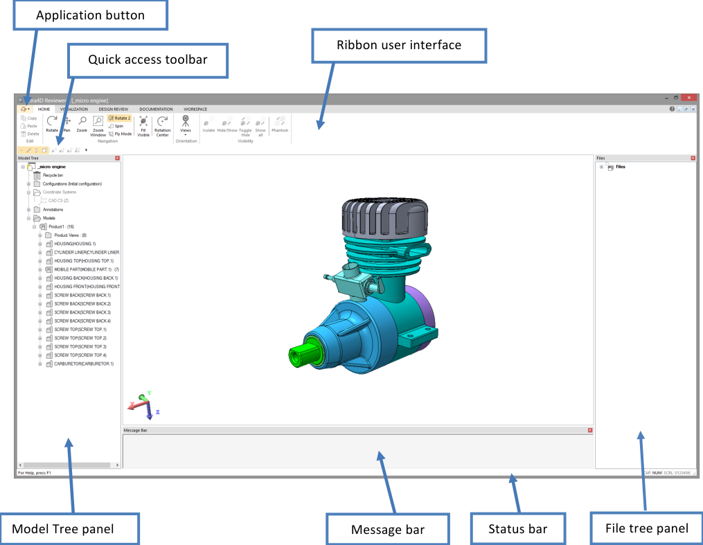
Tetra4D Reviewer™ user interface
The features of the software are accessible through a ribbon user interface. The ribbon is divided into several tabs, where all the product features are gathered to their usage. Inside the ribbon, the features are grouped in panels.
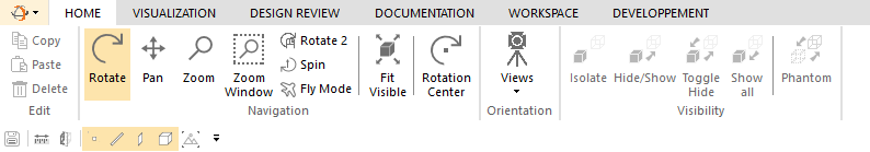
“HOME” tab
The Home tab provides the access to 3D control features.
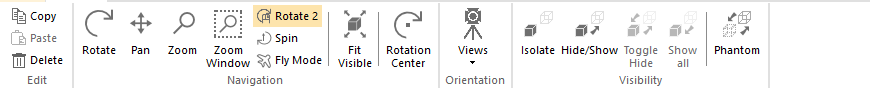
Edit panel

|
Copies the selected entities in the clipboard |

|
Pastes the clipboard into another document |

|
Deletes the selected entities |
Navigation panel

|
Main 3D navigation method |

|
Pan horizontally and vertically. |

|
Dynamic zoom. |

|
Zoom window |

|
Second navigation method |

|
Spin (rotation with vertical rotation axis) |

|
“Fly through” navigation mode |

|
Fit the visible parts to the screen |
|
Set a center of rotation |
Orientation panel

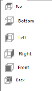
|
Activates a default view |

|
Sets the 3D in isometric view |
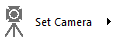
|
Activates the selected view according to the activate “view” coordinates system |
|
Sets the view orientation based on a selected 3D entity
Restore Config.View
From Selection
From Curve/Edge
From Face
From Coordinate Axis
Flip
|
Visibility panel

|
Makes the selected objects visible (hide all the unselected objects) |

|
Hide the selected objects |

|
Toggles the visibility of all the objects |

|
Makes all the objects visible |

|
Activates the “phantom display” mode |
“VISUALIZATION” tab
The Visualization tab provides the access to the features to control the selection options, the 3D rendering settings and to access to the CAD defined views and 3D notes and Product Manufacturing Information (PMI).

Advanced Selection

|
Opens a dialog box to find entities |

|
Selects entities based on their type 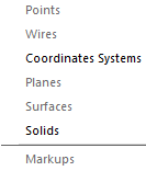
|
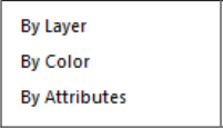
|
Select entities based on their layer, color, or attribute value |
Rendering panel

|
Changes the rendering mode of the 3D model 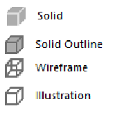
|

|
Toggles the 3D display in perspective or orthographic projection |
Display panel

|
Enables to change the level of details of the 3D model |

|
Enables to position the light(s) in the 3D scene |

|
Enables to select a background color for the 3D scene |
Advanced panel
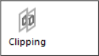
|
Activates cutting planes for visualization |

|
Displays a 2D grid to enable quick measurements |
Views/Filters panel

|
Provides the access to the CAD defined views. |

|
Provides the access to the CAD defined layers and filters. |
Markups panel

|
Toggles the visibility of the PMIs |
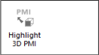
|
Highlights the PMIs that are linked to a selected entity |
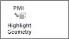
|
Highlights the entities that are linked to a selected PMI |

|
Toggles the visibility of the session markups |
Full Screen panel

|
Toggles the 3D window to Full Screen mode |
DESIGN REVIEW tab
The “Design Review” tab provides the access to the features that are dedicated to analyze and check the design of 3D models (measures, section, physical properties calculation…).
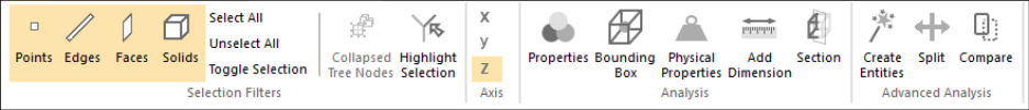
Selection filter
The selection filters define what type of information will be selected when the user clicks on a 3D object in the 3D window. When a specific selection filter is inactive, the corresponding entities can not be selected. Conversely, if the same selection filter is active, the these types of entities will be selected. When all selection filters are active, clicking selects any type of geometry close to the location you click.
Depending in the context of the feature, the selection filters may be automatically set. For example, when the Radius measurement tool is active, the Points, Faces, and Solids filters are deselected and only the Edges filter remains active so that only appropriate entities for a radius measurement can be selected by the user.
|
Selection of points |
|
Selection of edges |
|
Selection of faces |
|
Selection of solids |
|
Selects all the visible entities (ignoring the selection filters) Unselects all the selected entities Toggles selection |
|
Select the “collapsed tree node” when one of its component is selected in the 3D window |
|
Highlights the selectable entities when the mouse cursor hovers the 3D model |
Axis
|
Sets the main active axis according to the current active coordinates system |
Analysis panel

|
Provides general information for a selected object (type, color, attribute…) |
|
Enables to calculate the bounding box for the current selection |

|
Enables to calculate the physical properties (volume, weight) for the current selection |
|
Enables to measure and create dimensions |

|
Activates the section feature and make it possible to calculate sections |
Advanced analysis panel

|
Enables to create simple geometric entities based on the 3D models |
|
Enables to analyze if a plastic part is suitable for mold design |
|
Enables to compare different version of the same 3D model |
DOCUMENTATION tab
The “Documentation” tab provides the access to the features that are dedicated to analyze and check the design of 3D models (measures, section, physical properties calculation…).
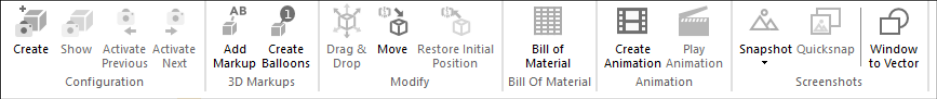
Configuration panel

|
Saves the current settings of the 3D window (visible parts, camera position…) in a new configuration |

|
Enable to create a new configuration with the current selection of objects |

|
Activates the previous configuration |

|
Activates the next configuration |
3D Markups panel

|
Creates a 3D markup |

|
Enables to create balloons attached to parts |
Modify panel

|
Allows to move components based on a 3D manipulator |

|
Allows to move components based on various methods |

|
Restore the initial position of a part that has been moved |
Bill of Material panel
|
Enables to create a part list |
Animation panel

|
Enables to create exploded views and animations |

|
Enables to play an existing animation |
Screenshots panel

|
Allows to create a screen shot (raster image) using one of the below methods |

|
Saves an image of the full 3D window . |

|
Saves an image of a user defined sub-area of the 3D window |

|
Adds the image of the full 3D window to the clipboard |

|
Saves an image of the full 3D window without asking for name |

|
Allows to create a vector graphics file of the full 3D window |
WORKSPACE tab
The “Workspace” tab provides the access to the features that are dedicated to control the visible areas of the software and to manage the documents’ windows.
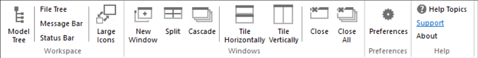
Workspace tab
|
Allows to display or hide the model tree panel |
|
Allows to display or hide the file tree panel
Allows to display or hide the message bar
Allows to display or hide the status bar
|
|
Allows to display large icons in the model tree and the file tree panels |
Windows tab

|
Creates a new window for the active document |

|
Split the document’s window into 4 views |

|
Arranges all the windows in cascade |

|
Arranges all the windows horizontally |

|
Arranges all the windows vertically |
|
Closes the active window |
|
Closes all windows |
Preferences tab

|
Provides the access to the preferences settings |
Help tab
|
Opens the user guide
Opens the web page of Tetra4D Reviewer™ support.
Opens a dialog box showing product information
|
“APPLICATION” button
This button provides the access to the “Files” related commands:

|

|

|

|

|

|

|

|

|

|

|
New |
Open |
Import |
Save |
Save back in PDF |
Save As |
Export |
Close |
Document LOG |
Exit |
Document panel
Grids
Grids are available as part of the background for 2D and 3D views. You control the color, style settings, and positions of the lines and units in the Grid preferences. The active coordinates system determines the grid center point. The grid lines adjust automatically when you change the zoom level. You can include the grid when you print.
Show or hide the grid
Click
in the VISUALIZATION tab.
Set grid options
Click
in the WORKSPACE tab.On the Grid tab, select options for the axes and scale.
Full Screen mode
Full Screen mode expands the document display to cover the entire screen. Full Screen mode hides the title bar, menus, toolbars, Model Tree, File Tree, Message bar, and Status bar. The only control visible is a floating toolbar with a single button. Clicking that button restores the standard work area view.
Activate Full Screen mode
Click
in the VISUALIZATION tab.
Escape Full Screen mode
Press the ESCAPE key.
The Ctrl-L keyboard short cut toggles between Full Screen and standard views.
Change the detail level
The on-screen display of 3D objects approximates the curves and angles in those objects. The Level of Detail setting determines how closely the display matches the actual geometry. The Level of detail directly affects the display. Indirectly, it affects a few other functions. For example, Level of Detail settings affect the selection modes when you take measurements or dimensions. Level of Detail also affects the results of calculations you make based on display information. It has no effect on calculations based on exact geometry.
Click
in the VISUALIZATION tab.Choose the level you want in Level of Detail.
Click Apply, or click Close to leave the Level of Detail unchanged.
Note
Level of Detail is available only for documents that contain actual geometry. The geometry depends on the content of the read CAD data.
Note
If you choose Advanced, the Advanced button opens a dialog box with the same options described for Physical Properties.
Change the background color
The background color is associated with the active configuration. You can set different background colors for individual configurations in a session file.
Click
in the VISUALIZATION tab.Select the color.
Note
Background changes are temporary if the active configuration is locked. To make the color change permanent, unlock the configuration after you change the background, and then immediately lock it again.
Advanced background options are available on the 3D Preferences tab.
Move the light source
The orientation of the light source associated with a configuration. You can set a different light source for individual configurations in a session file.
Click
in the VISUALIZATION tab.
Note
A light icon appears in the document pane.
Drag the light
 to change its position.
Note
As you drag the light, rotational axes appear that help you visualize the light position.
Arranging windows in the document pane
Tetra4D Reviewer is a multi-document application. It is possible to:
Work with several documents opened in different windows.
Copy and paste objects and entities between documents.
Create different views from the same document. The Split window command displays different views in the original window. The New Window command displays views in separate windows.
The document windows for files follow behaviors that are common for virtually all Microsoft® Windows® applications and system windows. For example, you can use the buttons in the upper right corner to minimize, maximize, and restore the window size. You can drag the title bars or edges of a file to resize it. For more information on these basic functions, see Microsoft Windows Help system.
Showing multiple views of sessions
You can open an individual session file in multiple windows. Each window can show a view of the assembly that is independent of the views shown in the other windows. For example, when you can adjust the point of view, display mode, and zoom in one window, other windows for the same session file remain unchanged.
You can resize the window like any other window by dragging an edge or corner of the window. Splitting, cascading, or tiling automatically arranges the windows in the document pane so that you can see all open files simultaneously.
Note
Dimensions and the markups that you create in a window appear in that window but not in other windows of the same session file.
Split views within one session window
Splitting divides the window into four sections. Each section shows a different default view of the 3D objects.
Click
in the WORKSPACE tab.Adjust the sashing that separates the four views as needed:
Drag the sashing horizontally or vertically to resize all four sections.
Drag the sashing to the edge of the document pane to close two of the sections.
Double-click the intersection of the two sashings to close three of the sections, leaving only one view open.
Open a duplicate window for the active session file
Click
in the WORKSPACE tab.
The appearance in the document pane doesn’t change because new window fills the area and shows the same view as the original window. You can resize and arrange the window by the techniques common to most Microsoft Windows applications.
Arrange multiple windows
Choose one button of the followings:
- : Arranges all currently open session files in identically sized windows that overlap.
- : Arranges all currently open session files in equal horizontal rows.
- : Arranges all currently open session files in equal vertical columns.
Model Tree panel
About the Model Tree
The Model Tree is a hierarchical structure that organizes the elements of the document by type. When multiple CAD files are open, each document appears in the Model Tree.
The structure for each open document includes five major categories:
Recycle Bin: Stores any entities you delete from that individual document.
Configurations: Saved views of the parts and some session information, such as Bill of Material and Animations created in that configuration.
Coordinate Systems: Coordinates systems defined by the CAD file and any custom coordinate system created by you.
Annotations: Markups and dimensions you create.
Models: The assembly and its component.
The Model Tree information is imported from the CAD source file. Some Reading mode preferences may impact the Model Tree structure. Model Tree icons indicate entity types. For example:
an assembly (or sub-assembly) icon
a component icon
a solid
a surface


Expanding and collapsing Model Tree structures
You can change your view of the Model Tree in two ways. You can expand individual levels, or you can simplify the tree structure by collapsing sub-levels of the hierarchy. Plus [+] and minus [-] icons expand and collapse individual tiers of the Model Tree. By default, the plus and minus signs are available at all levels of loaded assemblies. The Collapse command simplifies the tree structure by limiting the number of levels that appear. The Expand command reverses the Collapse command so that you can open all levels of the structure. Note: Plus and minus signs don’t appear under Models for part levels you’ve collapsed with a context menu command.
Expand and collapse individual elements
Click the plus sign [+] to expand a branch by one level.
Click the minus sign [-] to collapse all levels within that branch.
Note
In the Models section of the Model Tree, plus and minus signs appear only for loaded parts. If you load only an assembly structure, only the top assembly level will appear in the hierarchy.
Expand or collapse one or more levels
Expand commands on the context menu reveal the plus sign icons [+] for selected branches. Collapse commands collapse branches and hide the plus and minus signs for the selected elements.
Right-click a branch of the Models hierarchy and choose an Expand or Collapse command:
One Level: To restore the plus sign [+] to the next tier of the branch structure of the selected entity. (Available only on the Expand menu.)
Component: To change the availability of the plus [+] and minus [-] signs for entities nested under the selected element.
All: To change the availability of the plus [+] and minus [-] signs for the selected branch and the entities nested under that branch.
Note
Context menus for Models entities, such as assembly parts, bounding boxes, and sections, have Expand and Collapse commands. These commands don’t appear on context menus for other Model Tree entities, such as configurations and annotations.
Models hierarchies
The Models structure in the Model Tree expands to show several types of entities and information. The plus [+] and minus [-] icons beside the structure names expand and collapse the individual levels.
Primarily, the Models shows the assembly structure for the 3D objects. The arrangement of subassemblies, component parts, and items reflects the structure read from the CAD file. The assembly structure also contains structures for any Product Views and 3D PMI markups read from the CAD file.
Any Sections, Bounding Boxes, created entities, and imported or pasted-in parts appear under Models at the same level as the assembly.
About attributes
An attribute is non-geometric information linked to a part. The CAD data defines attributes information. That information is included when you import the CAD file into Tetra4D Reviewer.
Tetra4D Reviewer can include some attribute values in text that identifies individual parts of an assembly. This information appears at the fully expanded level for each individual component. Showing or hiding attributes is set at the document level. You can select which attributes to show or hide.
Show attributes in the Model Tree
In the Model Tree, right-click the document name and choose Show Attributes.
Under Attributes, select the attributes that you want to show:
Select and deselect check boxes for individual attributes.
Select the Select All
 or Unselect All
  for all attributes.
Note
Clicking an attribute name in the Attributes pane makes any known values for that attribute appear in the Values pane.
Recycle Bins
Recycle bins in the Model Tree stores entities that you delete from session files. Each open file has its own recycle bin. You can restore deleted items to the document. You can also delete items permanently by emptying the recycle bin.
Note
The recycle bins within Tetra4D Reviewer are independent of the Recycle Bin on the Windows desktop.
Restore deleted entities
Click the plus sign [+] to expand the Recycle Bin for the current document.
Right-click the entities that you want to restore and choose Restore.
Empty a recycle bin
Right-click the Recycle Bin that you want to empty, and choose Empty Recycle Bin.
File Tree panel
The File Tree panel provides you with the access to the incremental loading features. By default, the File Tree is closed when Tetra4D Reviewer starts.
You can open or close the File Tree with  in the WORKSPACE tab.
Show or hide information bars
The Message bar appears at the bottom of the work area, just above the Status bar. The Message bar can show information about any reading problems or direct your attention to part of the work area.
The Status bar appears across the bottom of the work area. In some contexts, the Status bar contains information about the current process. For example, the Status bar can provide cues about actions needed during the process of a specific task.
Show or hide an information bar:
Click
 in the WORKSPACE tab.
Click
 in the WORKSPACE tab.