Conversion Settings
In the Conversion dialog box, you can specify settings for converting 3D models for PDFs on various tabs. Or, choose a preset from the menu.
Note: The Acrobat Conversion dialog box does not appear if the “Don’t display dialog during conversion” option at the bottom of this dialog box is selected.
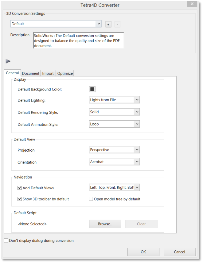
Tetra4D Converter Conversion Settings dialog box
Conversion Presets
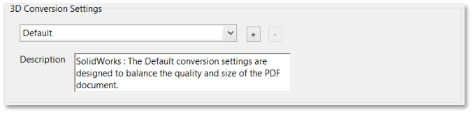
3D Conversion Settings Presets
Default: Provides optimum settings for the selected file format by balancing quality with PDF file size.
Custom: Indicates that you’ve selected one or more individual settings. Click the plus sign (+) to save your selections at a custom preset.
Visualization/Small File: Produces the smallest file size possible by applying compression, which may reduce image quality.
Visualization/High Quality: Produces detailed, high-quality PDFs, but may increase file size.
Collaboration: Produces high-quality, uncompressed PDFs.
Publishing: Produces high-quality, compressed PDFs.
Data Exchange: Preserves the exact geometry (or geometry compressed at 0.001 millimeter) for reuse with CAE and CAM applications.
U3D ECMA Standard Ed 3: Specifies U3D 3rd Edition format and 99% compression.
U3D ECMA Standard Ed 1: Specifies U3D 0.0 format and no compression.
Large File: Specifies settings to use for converting large assemblies
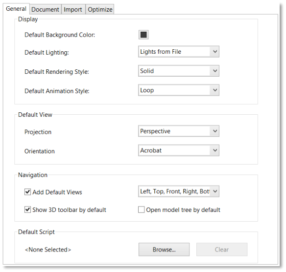
General Tab
These settings determine how the imported 3D model is presented in Acrobat Pro. Unlike the settings on the other tabs, General settings don’t affect the imported file itself.
Tetra4D Converter Conversion Settings General Tab
Note: Some of these settings can be changed after you import a file by using the options on the 3D toolbar.
Display
Default Background Color: Identifies the color behind the 3D model. Click the color swatch to
make changes.
- Default Lighting: Shows the lighting style to be used on the imported file.Note: For best performance when manipulating 3D models, select the Headlamp option.
Default Rendering Style: Shows the rendering style used for the imported model. Select a different style from the menu, if needed.
- Default Animation Style: For models created with animation, this setting determines how the animation runs in Acrobat.
Default view
- Projection: Defines the projection mode used in the default view of the PDF document.Note: The default view is the one used to create the 3D annotation poster image.
The choices are:
Perspective
Orthographic
- Orientation: Defines the orientation used for the default view.Note: The default view is the one used to create the 3D annotation poster image.
Several preset options are proposed:
Acrobat: This option is the default one. It corresponds to the acrobat orientation that has been used for the previous versions of Tetra4D Converter.
This preset orientation can’t be modified.
CAD software: These options define orientations that correspond to the default orientations of the CAD software.
These preset orientations can’t be modified.
Manage orientation: This option makes it possible to define other orientations and to save them.
When selecting “Manage orientation”, the following dialog is shown:
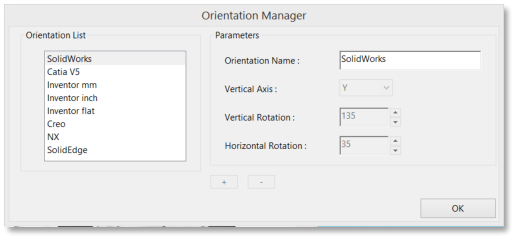
Manage Orientation Dialog
Define a new orientation name.
Select the vertical axis in the drop down list
The vertical axis is the axis from the CAD file that will be vertical in the PDF document
Define the Vertical Rotation value
The first rotation is done around the vertical axis of the 3D annotation
Define the Horizontal Rotation value
The second rotation is done around the horizontal axis of the 3D annotation
Click on the “+” icon to save the settings
Default Script
Specifies the JavaScript file that runs if a 3D model is enabled. If the 3D model you’re importing doesn’t include embedded JavaScript, click Browse to specify the JavaScript file you want to run.
Document Tab
Use the Document settings to determine the layout of the page containing the 3D model, set up read/write permissions for the file, and encrypt the converted file.
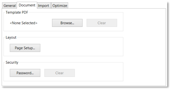
Tetra4D Converter Conversion Settings Document Tab
- Template PDF: Specifies an existing PDF file in which to place the 3D model. Click Browse toselect a PDF to use. Click clear to remove the template and set up the page using the Layoutoptions.
- Layout: Select Page Setup to change the margins, page size, and page orientation (portrait or landscape) of the converted model.
- Security: Set an encryption level for the PDF, require a password to open it, and set editing and printing permissions.
Import Tab
These settings determine what entities and information from the file that is under process will be imported into the 3D PDF document.
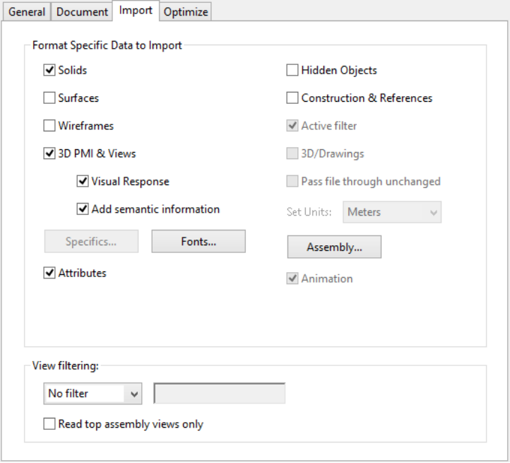
Tetra4D Converter Conversion Settings Import Tab
Format Specific Data to Import
Specify the types of information that you want to import into the 3D PDF document when reading the native 3D CAD model or standard 3D file. The available options reflect the file format of your 3D model.
Entities and information
Solids: Specifies if solid objects are read.
Surfaces: Specifies if surface objects are read.
Wireframe: Specifies if wireframe entities are read.
3D PMI & Views: Specifies if PMIs and views are read.
Attributes: Specifies if meta-data linked to the objects (parts) are read.
Hidden objects: Specifies if the hidden entities are read.
Construction & References: Specifies if construction & reference entities like planes and axes are read.
Active filter: Specifies what layers and filters are read.
3D/Drawing: Specifies if read information are 3D or 2D.
Assembly view filtering: Specifies when an assembly is read if the native CAD views that are defined in the components are taken into account. This option applies for CATIA V5 and Autodesk Inventor formats.
View filtering: Specifies what types of views are read or ignored.
The filters are:
- View name: Specifies what views are ignored or kept, based on the name of views.The criteria is a string of characters that is searched in the view names.
- Read top assembly views only: Specifies if the views defined in the components ofthe assembly are read or not. This setting applies to CATIA V5 and Inventor formats only.
Specifics
Click Specific to have the access to some reading options or features that are available only with the file format currently under reading. The Specific option is proposed for the following CAD formats:
Creo (Pro/ENGINEER),
NX,
STEP.
Note: Refer to STEP: Specific reading options to have detailed explanations about STEP validation properties.
Fonts
Specifies how the PMIs are managed when the 3D PDF document is created:
Set up substitute fonts for the fonts in the original 3D file,
Set up substitute color for the colors of the PMIs in the original 3D file,
Set up a directory where to look for CAD proprietary fonts.
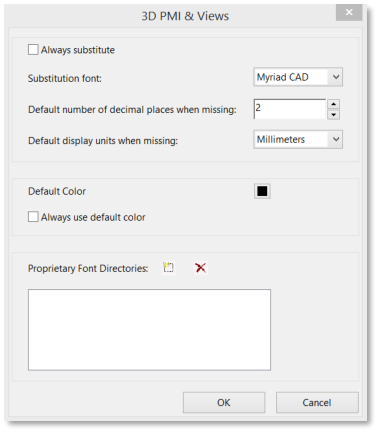
Tetra4D Converter Conversion Settings Import Tab: Fonts option
Assembly
Click Assembly to define the directories to search parts that are not in the current folder. For large assemblies in which the master file refers to many parts and subassemblies, some parts can be in multiple directories.
Optimize Tab
Adjust the Optimize settings to select the file format to convert 3D data to and the corresponding compression.
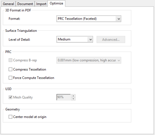
Tetra4D Converter Conversion Settings Optimize Tab
3D Format in PDF
Choose between U3D and PRC conversion formats in the Format menu. The file format of your 3D model determines which settings are available.
Surface Triangulation
Level of Detail
Specify the level of detail used to display the 3D model. Higher settings produce more accurate results. Lower levels of detail are useful for quick visualization with reduced visual quality. Two additional settings allow you to set specific height and angle values:
User Defined: Use to produce good quality model rendering for visualization and 3D printers
Controlled Precision: Use to create more accurate meshes for export to 3D printers.
Level of detail can only be set when you import a model. If you import a model with User Defined tessellation, you must reimport the file to create the tessellation required for 3D printers.
When you select either User Defined or Controlled Precision, click Advanced to define the triangulation parameters.
Advanced
- Chord Height Ratio: Specifies the percentage of bounding box used to compute chord height.Set a value from 50 through 10,000.
Wireframe Chord Angle: Specifies the maximum angle between two contiguous segments of wire edges for every face. The value must be from 10 through 40.
Maximum Chord Height: Specifies the maximum distance, in millimeters, between surface and tessellation.
Minimal Triangle Angle: Specifies the angle between two contiguous segments of wire edges for every face. The value must be between10 and 30.
Binary File: Creates a binary version of the STL output file, which is smaller than the standard ASCII STIL file.
PRC
- Compress B-rep To: The amount (in millimeters) of lossy compression applied to geometry.For best results when exporting geometry, set the amount to 0.001 or leave this option unselected.
Note: You can compress the geometry after you convert the 3D file to PDF by right-clicking the 3D model and choosing Optimize PDF.
- Compress Tessellation: Applies lossy compression to polygons.
- Force Compute Tessellation: Reads the B-rep and computes the tessellation according to the selected level of details criteria. Retains only tessellation data in the PDF document.Note: This option applies for some CAD formats where a tessellation is stored in the native files (CATIA V5 and SolidWorks). If not checked, the native tessellation is directly read, leading to a shorter reading time, but ignoring the level of details.
U3D
Mesh Quality: Controls the quality relative to the percentage of lossy compression applied to the image files. Higher percentages indicate less compression and better image quality. A setting of 100% applies no compression.
Geometry Center Model at Origin: Translates the entire model so that the center of its bounding box is at the origin [0,0,0] of the XYZ coordinate system.
Customize a conversion preset for a 3D file type
You can create your own conversion presets for different types of 3D files, making it easy to reapply all the individual options you use most often for a specific type of 3D file.
Presets are tied to the 3D format. For example, if you create a preset for CATIA V5 files, that preset appears only when converting CATIA V5 files. You can create multiple presets for each 3D format. When you convert or capture a 3D file, the most recently used preset for that file type is selected.
Choose Edit > Preferences, and then choose “Convert to PDF” under Categories.
- In the central panel of the Preferences, select the 3D file format to which the custom preset will apply, and then click Edit Settings.Note: If you select a non-3D file type, the Edit Settings button may not be available or it may open a different dialog box.
Using the four tabs in the Conversion dialog box, specify the settings you want to include in the preset.
Above the tabs, in Description, type something that will help you to recognize the preset, such as its intended purpose or parameters.
Click the Add Preset icon.
Type a name for the preset, and click OK.
Click OK to close the Tetra4D Converter Conversion dialog box, and, if necessary, click OK to close the Preferences dialog box.
Note: You can delete a custom preset by reopening the Tetra4D Converter Conversion dialog box, selecting the preset from the menu, and then clicking the Minus Preset button.
Convert large assemblies
Converting large assemblies with numerous unique components to PDF can be both time-consuming and memory- intensive. For best results, create a tessellated representation of the assembly using PRC conversion settings. If the CAD file includes saved tessellation entities, Tetra4D Converter uses these entities instead of creating new ones.
Choose File -> Create PDF -> From File -> Select the 3D file or part.
In the 3D PD Converter Conversion dialog box, click the Import tab.
Click Assembly to select the appropriate file path for part files, and click OK.
Click the Optimize tab and choose PRC Tessellation (Faceted) from the Format menu.
From the Level of Detail menu, select Medium. Select any other options, and then click OK.
Note: For you to complete this task, PRC settings must be available on the Optimize tab of the Tetra4D Converter Conversion dialog box.
Format specific reading options
STEP: Specific reading options
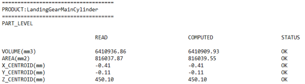
The STEP AP 242 standard supports “validation properties”. The “validation properties “ are additional meta-data added in the STEP file, meant to give the ability to validate a CAD data translation process (Conversion of CAD files from one CAD system into a different one, using STEP as intermediate format). The validation properties apply to parts and assemblies, geometry, PMIs and views.
This chapter describes how the validation properties already existing in a STEP file can be exploited during the conversion of this STEP file into a 3D PDF document.
Choose File -> Create PDF -> From File -> Select the STEP file.
In the 3D PD Converter Conversion dialog box, click the Import tab.
Click Specific to access the Validation properties related options.
- Click Read Validation properties in order to read the validation properties that are present in the STEP file.Note: The read validation properties can be accessed in the Log file.
- Click Compute validation properties in order to compute the validation properties using the information from the 3D annotation.Note: after the conversion of the STEP file into a 3D PDF document, validation properties will becalculated based on the 3D PDF information and then compared with the read validationproperties. The validation properties are compared with the Geometry and PMI tolerances thatare defined in this panel.
Use the Geometry and PMI sub-panel to define the tolerances that will be used when comparing the read validation properties and the computed one.
Click (optional) Add Result To Name in order to add the results of the comparison to the names of the entities in the 3D annotation data tree.
Click on OK to validate the options and continue the conversion process.
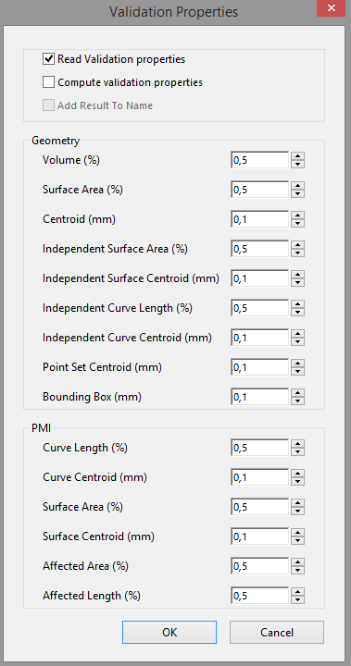
STEP Reader specific options (Validation properties feature)
Access to validation properties
The validation properties can be accessed after the conversion of the STEP file into a PDF document as follows:
- In the Model TreeNote: If validation properties are only read (Compute validation properties not checked), the validation properties are presented in the Model Tree like other meta-data.
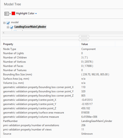
or
- Choose Tetra4D Converter (top menu) -> Last log fileNote: If validation properties have been computed (Compute validation properties checked), the validation properties are presented in the Model Tree and also in the LOG file.