
Interacting with 3D Models
Displaying 3D models
In Tetra4D Converter, you can view and interact with high-quality 3D content created in professional 3D CAD or 3D modeling programs and embedded in PDFs. For example, you can hide and show parts of a 3D model, remove a cover to look inside, and turn parts around as if holding them in your hands.
A 3D model initially appears as a two-dimensional preview image. Clicking the 3D model with the Hand or Select tool enables (or activates) the model, opens the 3D toolbar, and plays any animation.
3D Toolbar Overview
The 3D toolbar appears after you click the 3D model with the Hand tool. This action activates the 3D model and plays animations that are set to play when the file is enabled. The 3D toolbar always appears in the area above the upper-left corner of the 3D model and cannot be moved. A small arrow appears to the right of the Rotate tool, which you can click to either hide or expand the toolbar.
You can use the 3D toolbar to zoom in and out, rotate, and pan across the object. Use the Model Tree to hide/isolate parts, or make parts transparent.
You manipulate a 3D model by selecting and dragging various 3D navigation tools. When you navigate in 3D, it helps to think of it as viewing the stationary 3D model from a camera’s perspective. You can rotate, pan (move up, down, or side-to-side), and zoom in or out.
Note: You can hide the toolbar by right-clicking the 3D model and choosing Tools > Hide Toolbar. To show the toolbar, choose Show Toolbar from the same context menu.
3D toolbar view controls
- Default View: Returns to a preset zoom, pan, rotation, and projection mode of the 3D model.Use the Options menu in the View pane of the Model Tree to set a different view as the default. Or use the Manage Views command on the 3D toolbar Views menu to set a different view as the default.
Note: If an object ever moves out of your view, you have, in essence, turned your camera away from the object. Click the Default View icon on the 3D toolbar to move the object back into view. You can also right click in the 3D scene and select Part Options > Fit Visible to bring the model to view and reset the center rotation point.
Views menu: Lists any views defined for the current 3D model.
Toggle Model Tree: Opens and hides the Model Tree.
Play/Pause Animation: Plays or pauses any JavaScript-enabled animation. The Play/Pause Animation pop-up menu opens a slider that you can drag back and forth to move to different times in the animation sequence.
Use Orthographic/Perspective Projection: Toggles between displaying perspective and orthographic projection of the 3D object.
Model Render Mode menu: Determines how the 3D shape appears.
Enable Extra Lighting menu: Lists the different lighting effects that are available to enhance the illumination of the 3D object. Experiment to get the visual effects you want.
Background Color: Opens the color picker, which you can use to select a different color for the space surrounding the 3D object.
Toggle Cross Section: Shows and hides cross sections of the object. Click the pop-up menu to open the Cross Section Properties dialog box.
Add 3D Comment: Enables you to add a sticky note to any part of the 3D model. The note stays with the view.
Examples of model rendering modes
The model rendering modes include combinations of factors that affect the appearance of the 3D object. The illustration below shows a simple object rendered in each of the available modes.
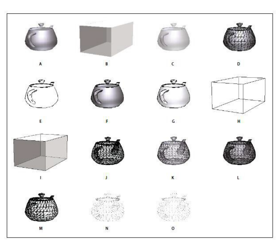
Model rendering modes: A. Solid B. Transparent Bounding Box C. Transparent D. Solid Wireframe E. Illustration F. Solid Outline G. Shaded Illustration H. Bounding Box I. Transparent Bounding Box Outline J. Wireframe K. Shaded Wireframe L. Transparent Wireframe M. Hidden Wireframe N. Vertices O. Shaded Vertices
Change rendering mode, lighting, projection, and background
The model rendering mode determines the surface appearance of the 3D model. The default rendering mode is usually solid, but you can also choose another rendering mode. You can also change the lighting of the 3D model as well as the background.
Changing the appearance of the 3D model
Use items on the 3D toolbar to make any of these changes:
To change the rendering mode, choose an option from the Model Render Mode pop-up menu.
To view an orthographic projection, click the Use Orthographic Projection button. An orthographic projection effectively removes a dimension, preserving the size ratio between objects but giving the 3D model a less realistic appearance. Click the button again to use perspective projection.
To turn lighting on or off, or to change lighting, choose an option from the Enable Extra Lighting pop-up menu.
To change the background color, click the arrow next to the Background Color swatch and choose a color.
Note: Model rendering modes, lighting schemes, and background color options are also available by right-clicking the 3D model, and then clicking Viewing Options. Model rendering modes also appear under the Options menu on the Model Tree.
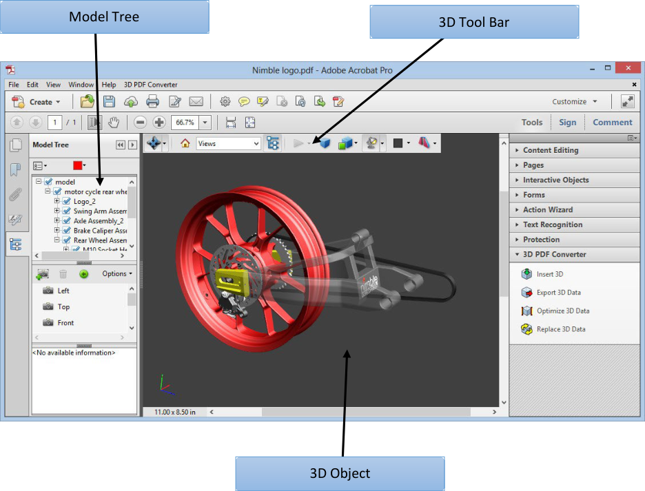
Model Tree Overview
The Model Tree appears in the navigation pane on the left side of the work area. You can also open the Model Tree by clicking the Toggle Model Tree button on the 3D toolbar. Or, right-click the 3D model and choose Show Model Tree.
The Model Tree has three panes, each of which displays a specific type of information or controls.
- Structure pane: The topmost pane shows the tree structure of the 3D object. For example, a 3D object depicting a car has separate groups of objects (called nodes) for the chassis, engine, and wheels. In this pane, you can move through the hierarchy and select, isolate, or hide various parts.Product Manufacturing Information (PMI) appears as a group of items on the same hierarchical level as its related object or assembly.
- View pane: The middle pane lists the views that have been defined for the 3D object. Whenyou change a view, click one of the listed views to return the 3D model to a saved state.You can also add to and edit views in the View pane. For example, after you isolate and rotatea part, you can save that particular view, including the camera angle, background, lighting,and other attributes. This feature is not available for Acrobat Reader.
- Object Data pane: The lower pane displays other information, including properties andmetadata, if any, about the object or part. You cannot edit this information for 3D objects inAcrobat.
Model Tree
Note: To change the default behavior for the Model Tree, open the Preferences dialog box and under Categories, select 3D and Multimedia. Then choose an option from the Open Model Tree On 3D Activation menu.
The author of the PDF can set up a 3D model in the conversion settings so that clicking it automatically displays the Model Tree.
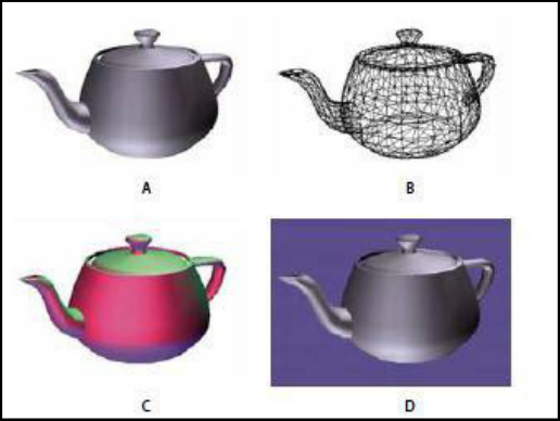
Hide, isolate, and change the appearance of parts
Some 3D models are composed of individual parts. You can use the Model Tree to hide or isolate parts, zoom in to parts, or make parts transparent. Parts that show in the 3D model appear in the tree with a check mark next to them.
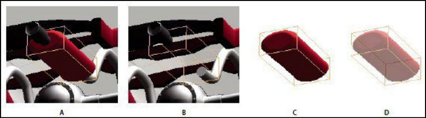
Manipulating parts A. Selected part B. Hidden part C. Isolated part D. Transparent part
In the 3D model, use the Hand tool to click the part you want to manipulate. If a preference setting prevents you from using the Hand tool, select the part in the Model Tree list.
Note: The items that appear on the Options menu depend on whether the 3D model is composed of just one part or multiple parts. Many of these options are also available by right-clicking a part in the 3D model.
From the Options menu in the top pane of the Model Tree, choose any of the following:
Model Render Mode: Changes the surface appearance of the entire 3D model according to the item you choose from the submenu: Transparent Bounding Box, Solid, Transparent, Solid Wireframe, and so on.
Show All Parts: Displays the entire 3D model.
Fit Visible: Displays all visible parts and centers them in the view.
Show Physical Properties: Displays the surface area and volume (if available) in the Object Data pane of the Model Tree.
Display Bounding Box: Displays the box that encloses the 3D object or selected parts of the model.
Set Bounding Box Color: Changes the color of the bounding box. Choose this option, select a color, and then click OK.
Hide: Displays the model without showing the selected parts. You can also select and deselect check boxes in the top pane of the Model Tree to hide and show different parts.
Isolate: Displays only the selected part, hiding all others.
Isolate Part: Displays the geometry, the Product Manufacturing Information (PMI), and all views (including PMI views) for the isolated part only. Views and information for all other parts are hidden or deselected. Changes occur in the Model Tree as well. In the Structure pane (top), only the isolated part is selected. The structure of the other parts is available but deselected. The View pane (middle) lists only the views that have been defined for the isolated part, including PMI views. If you click a view, you see only the PMI for that view in the document pane. (To view the PMI for the isolated part, make sure 3D PMI is selected in the Structure pane.) The View pane hides views related to the assembly or other parts, including custom views created in Acrobat. You can add parts to the view by selecting them in the Model Tree. You can also use the Hide/Show commands in the options menu of the Model Tree.
To cancel the isolated part, do any of the following:
Zoom to Part: Changes the center focus from the entire 3D model to the selected parts. This setting is especially useful for rotating a part, allowing the rotation to occur around the center focus of the part rather than around the entire model.
Part Render Mode: Displays all of the rendering modes that are available for the part. The rendering mode changes the appearance of the 3D model according to the rendering mode you choose.
Transparent: Displays a see-through version of the selected part.
Export as XML: Creates a separate XML file of either Whole Tree or Current Node of the 3D model.
Export as CSV: Creates a separate file in CSV format that contains all of the model data. You can export the data from the whole Model Tree or a selected node. The file can be opened in any program that supports CSV formatting, such as Microsoft Excel.
Note: If the 3D model includes Product Manufacturing Information (PMI), options for showing and hiding the PMI are available on this menu.
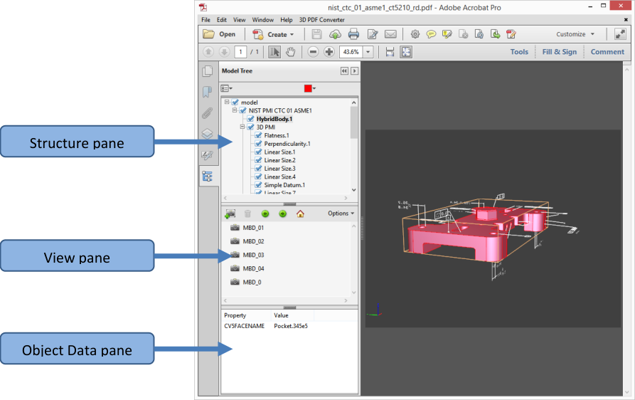
View Product Manufacturing Information (PMI)
If Product Manufacturing Information (PMI) from the original CAD file was imported during PDF conversion, you can view this information in the 3D model. PMI is added to a CAD drawing to communicate manufacturing or inspection requirements and other data for a part or feature. CAD applications also call this information Geometric Dimensioning and Tolerancing (GD&T) or Functional Tolerancing and Annotation (FT&A).
Designers typically add PMI to one of the six standard views (top, bottom, right, left, back, or front) in the CAD application. Or they create unique views for this information. You can view PMI in the 3D model by selecting these views.
Import Product Manufacturing Information (PMI).
Click the 3D model to activate it, and then click the Model Tree icon in the 3D toolbar.
In the Structure panel (top) of the Model Tree, click 3D PMI to view the names of each notation.
To view PMI in the 3D object, do one of the following:
Select a view associated with PMI (if one is available) in the View panel (middle) of the Model Tree. Only the PMI in the selected view is visible in the 3D model.
Right-click a part and choose Part Options > Isolate to see the PMI for the selected part.
Select an individual notation in the Model Tree to highlight it in the current view.
Note: The font used for PMI text must be installed on your computer for the text to display correctly.
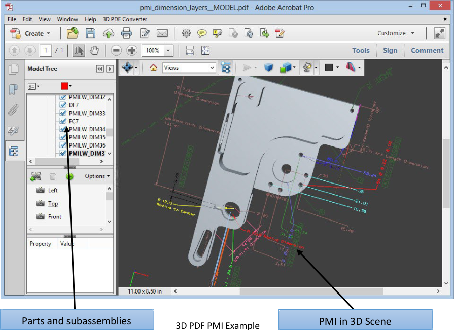
3D PDF PMI Example
Create Cross Sections
Displaying a cross section of a 3D model is like cutting it in half and looking inside. Use the Cross Section Controls dialog box to adjust the alignment, offset, and tilt of the cutting plane.
Before and after cross section
Click the Toggle Cross Section icon on the 3D toolbar to turn on or off the cross section.
(Optional) Click the arrow next to the Toggle Cross Section icon, and choose Cross Section Properties, which opens the Cross Section Properties dialog box. Then do any of the following:
Change settings under Alignment, Display Settings, and Position and Orientation.
Click the Save Section View button to save the current cross-sectional view. (The saved view will appear on the Views menu in the 3D toolbar and in the View pane of the Model Tree with a default name, SectionView[n].)
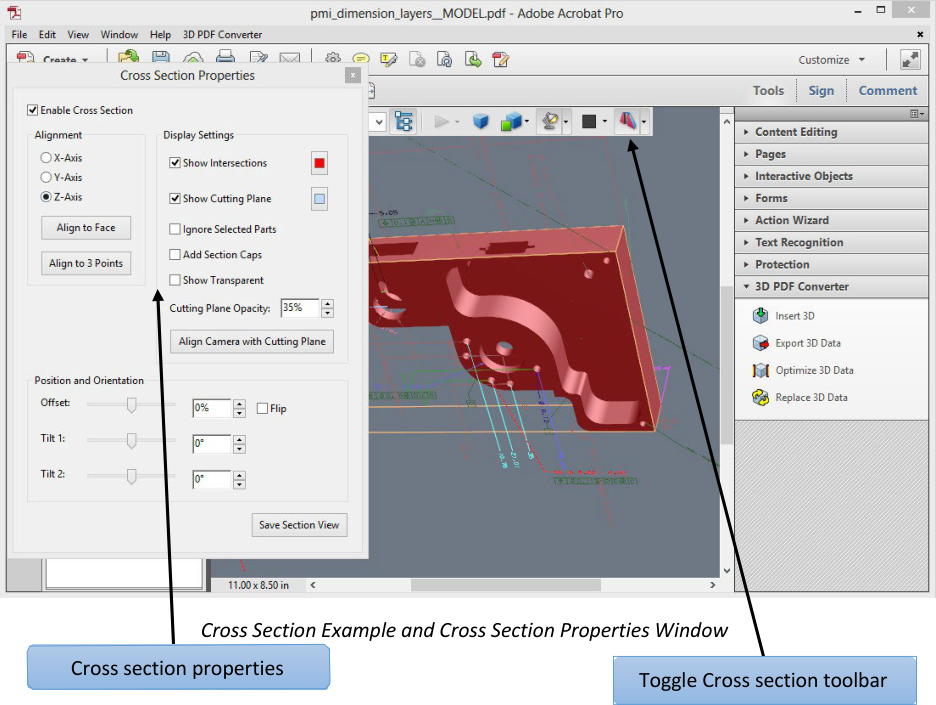
Cross-Section Properties
Changes you make here are applied immediately. To see these changes, make sure that the Cross Section Properties dialog box does not block your view of the active 3D model. The Cross Section Properties dialog box remains on top if you focus or interact with the underlying PDF. To close it, click the Close button in the upper-right corner.
Enable Cross Section: When selected, makes the other options available.
Alignment: Determines the axis (x, y, or z) to which the cross-section aligns.
Align to Face: Cuts the cross-section on a plane defined by the surface of any face that you then click in the 3D model. (The dialog box is dimmed until you click the face of a model part.)
Align to 3 Points: Cuts the cross-section on a plane defined by any three points that you click the 3D model. (The dialog box is dimmed until you click three points of a model.)
Show Intersections: Indicates where the cutting plane slices the 3D model by adding a colored outline. Click the color swatch if you want to select a different color.
Show Cutting Plane: Displays the two: dimensional field that cuts the 3D model. Click the color swatch to select a different color, and enter a different percentage to change the opacity of the plane.
Ignore Selected Parts: Removes the selected parts from the cross-section view.
Show Transparent: Displays parts that are not part of the cross-section.
Cutting Plane Opacity: Defines the transparency level of the cutting plane.
Align Camera with Cutting Plane: Rotates the 3D model so that it is level with the cutting plane.
Offset: Determines how much of the 3D model is sliced. Drag the slider left or right, or change the percentage.
Note: To understand how each axis divides the 3D model, select an axis and then drag the Offset slider back and forth. Observe the changes in the embedded 3D model.
Flip: Reverses the cross-section. For example, if the top half of the model is cut off, click Flip to display the top half and cut off the bottom half.
Tilt sliders: Determine the angles between the cutting plane and the axes. Drag the sliders left or right, or change the percentages.
Save Section View: Opens the View Properties dialog box in which you can select the display properties to save with the view. After you select the properties to save, the cross-sectional view is added to the list of views in the 3D toolbar and the Model Tree. The saved view is
given a default name, SectionView[n].
Display properties that you choose not to save revert to the setting of the previous view. For example, if you do not save the background color, the cross-section view retains the background color of the previously displayed view.
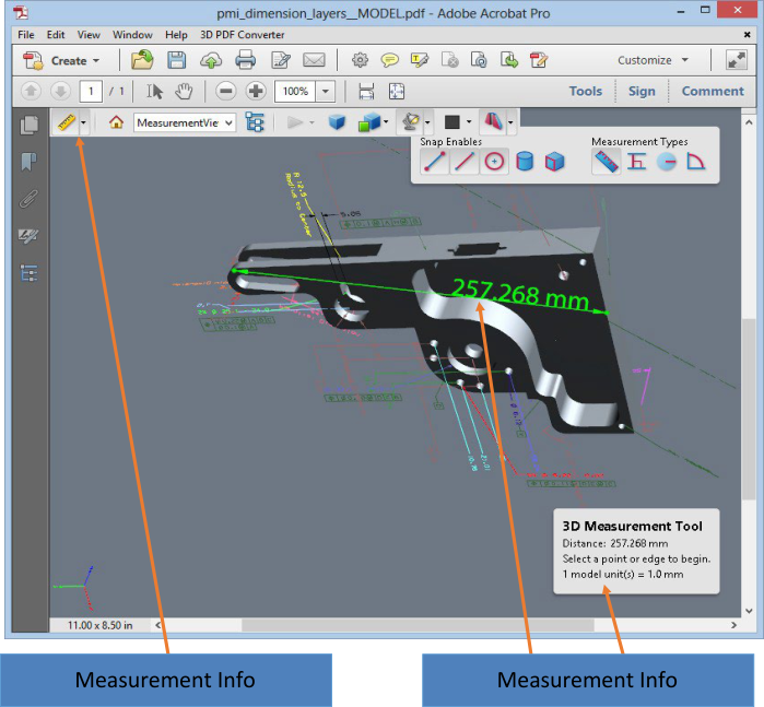
Measure 3D objects
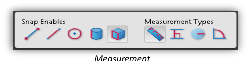
Use the 3D Measurement Tool to measure 3D models. You can create measurements between combinations of points or edges of the 3D model. As you move the pointer over the 3D model, specific points and edges are highlighted. The 3D Measurement Tool supports four types of measurements: perpendicular distance between two straight edges, linear distance between two points, the radius of circular edges, and the angle between two edges (or three points).
You can associate 3D measurements with specific views. If the default view is active when a measurement is added, a new measurement view is created. This view is added to the view hierarchy in the Model Tree. The measurement is associated with that view only. The measurement shows up as a child of the view.
You can also display comments while taking measurements. These comments (also called measurement markups) are preserved after the document is closed.
Cross Section Example and Cross Section Properties Window
Click a 3D model in a PDF to enable it.
Click the 3D Measurement Tool icon on the 3D toolbar. (If the 3D toolbar view is set for consolidated tools, select the 3D Measurement tool from the pop-up menu next to the Navigation tool.)
Select the options you want in the Snap Enables and Measurement Types areas of the 3D Measurement Tool palette.
Right-click the model background, and change the options as needed. Leave the 3D Measurement Tool palette open.
Measure the 3D model:
To measure the distance between two positions on the 3D model, click to set a start point. Then move the pointer to another location or an edge.
To measure the circumference of a round shape, move the pointer to the edge of the shape so that a circle appears, and click once.
To create and set an annotation on the measurement, right-click the object background and select Change Markup Label. Type a markup label. Measure the 3D model as described previously. Click to set the end point for the measurement, and then click a third time to set the location of the measurement and label.
To save a measurement as a comment, select the Hand tool, right-click the measurement, and click Convert to Comment.
To discontinue a measurement, right-click and choose Cancel Measurement.
To delete a measurement markup, click it with the 3D Measurement Tool and press Delete.
Note: To learn how to rotate, pan, zoom, and snap while you measure, right-click the model and choose 3D Measurement Navigation Tips.
Snap Enables options in the 3D Measurement Tool palette
Snap Enable |
Icon |
Description |
|---|---|---|
3D Snap to Edge Endpoints |

|
Snaps to the entire edge. |
3D Snap to Linear Edges |

|
Snaps to a straight-line segment of an edge. |
3D Snap to Radial Edges |

|
Snaps to a circumference. |
3D Snap to Silhouettes |

|
Snaps to the apparent edge of a part, such as the side of a cylinder. |
3D Snap to Planar Faces |

|
Snaps to the geometric plane making up a face of the part. |
Measurement Types options in the 3D Measurement Tool palette
Measurement Type |
Icon |
Description |
|---|---|---|
3D Point To Point Measurement |

|
Measures the distance between two positions on the 3D model.
Click to set a start point, and then click another location to set an end point or edge.
|
3D Perpendicular Dimension |

|
Measures the distance between two edges taken at a right angle to the starting edge. |
3D Radial Dimension |

|
Measures the radius at the location clicked. |
3D Angle Measurement |

|
Measures the angle between two edges. |
Units and markup options
To use the Units and Markup measurement tools, select the 3D Measurement Tool, and then right- click inside the model.
Define Model Units: Select to change the measurement units.
Enable Coordinate Display: Displays or hides the coordinates of the mouse pointer location in the Measurement Info Window.
Change Markup Label: Type the text that you want to appear with the measurement, both in the 3D model area and in the Comments panel. (Not available if Measurement Markup is not selected.
Disable Measurement Markup: Select when you want to take measurements in a model, but not add them to the document. The measurements are only visible while the current measurement is active. If you start another measurement or change tools, the markup disappears.
Don’t Snap To 3D Content: Disables the ability to snap the insertion point to a likely target. Select this option to improve performance when you are working with a large model. Return to Snap To 3D Content to ensure precise measurement in 3D objects.
3D Measurement Navigation Tips: Opens a dialog box that lists the keyboard shortcuts for several navigation shorts. You can use these shortcuts while you are measuring.
Preferences: Opens the Measuring (3D) Preferences dialog box.
Hide/Show Measurement Info Window: The Measurement Info Window displays the Units and Markup settings for the model. Select to remove the window from the model window.
Hide/Show Measurement Toolbar: Removes/displays the 3D Measurement Tool palette.
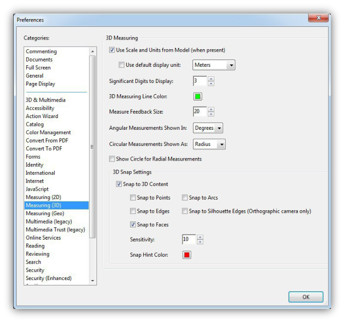
Measuring preferences
Change the 3D Measuring preferences to determine how 3D data is measured. These options appear in the Measuring (3D) panel of the Preferences dialog box.
Note: In Adobe Reader, these preferences apply to PDFs that have commenting enabled (Reader Enabled).
Measurement Preferences Window
3D Measuring
Use Scales and Units from Model (When Present): Displays measurements based on the model units, if present, generated from the original 3D model. Deselect this option to specify the units of measurements manually. This setting can be changed in the 3D Measurement Tool palette.
Use Default Display Unit: Uses units of measurement that you specify here rather than the measurement units in the 3D model.
Significant Digits to Display: Specifies the maximum number of digits in the measurement number.
3D Measuring Line Color: Specifies the color of the line that appears when you click or drag to measure an object.
Measure Feedback Size: Sets the text size for the measurement display.
Angular Measurements Shown In: Specifies units as either degrees or radians.
Circular Measurements Shown As: Designates whether the diameter or radius is measured for circular parts.
Show Circle For Radial Measurements: Displays the circumference associated with the radial measurement.
3D Snap Settings
Turns on snap and specifies whether points, arcs, edges, silhouette edges, or faces are snapped to. Sensitivity indicates how close the pointer must be to the item being snapped to.
Snap Hint Color: specify the color of the snap line that appears when you hold the pointer over the 3D object.
Change camera properties
Camera properties define the precise angle and positioning for a view of an object. Camera properties make up a camera view, which can be used both between views and between files.
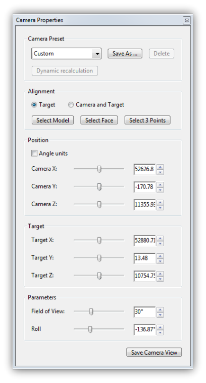
Camera Properties Window
On the 3D toolbar, click the Camera Properties icon. If you don’t see the icon, click the arrow next to the navigation tool on the left side of the 3D toolbar.
In the Camera Properties dialog box, click Save As to name a new camera view, or select an existing view from the menu.
Move the Camera Properties dialog box so that you can see the 3D model. Select a camera alignment:
Select Target to align the camera properties only to the target position.
Select Camera and Target to align the camera properties to both the camera direction and the target position.
Select the type of alignment:
Select Model: After you select this option, click a 3D model in the document. The Camera Properties dialog box shows the current camera position.
If Target is selected, the new position of the camera target is the center of the selected model.
If Camera and Target is selected, the position of the camera target is the center of the selected model. The camera is aligned to the selected model.
Select Face: After you select this option, click a face of the 3D model in the document. The Camera Properties dialog box shows the current camera position.
If Target is selected, the new position of the camera target is the center of the selected face.
If Camera and Target is selected, the position of the camera target is the center of the selected face. The camera is aligned to this face.
Select 3 Points: After you select this option, select three points on the same or different models in the document. The Camera Properties dialog box shows the current camera position.
If Target is selected, the new position of the camera target is the center of the three selected points.
If Camera and Target is selected, the camera target is the center of the three selected points. The camera position is aligned to the plan composed by the three selected points.
In the Position section, select Angle Units to change the X, Y, and Z values to Azimuth, Altitude, and Distance. These values enable you to manipulate the camera by azimuth (distance) and altitude (X axis), and to zoom using the distance value.
Move the sliders in the Camera and Target positions to the desired location.
To change the focal angle of the camera, drag the Field Of View slider to the desired degree.
To change the roll angle of the camera, drag the Roll slider to the desired degree.
Click Save Camera View to save the settings and add the view to the Model Tree.
The view is added to the Model Tree with the default name of CameraView[n], with [n] being an incremental number. You can rename the camera view in the Views list.
Set 3D views
The default view of a 3D model lets you quickly revert to a starting point at any time as you interact with the model. A default view is different from a preview, which determines what the 3D model looks like when it’s not activated. The list of all available views for the 3D model appears in the Views menu on the 3D toolbar and in the View pane of the Model Tree.
You can also create additional views of the 3D model in Acrobat that let you quickly navigate the 3D content as you want (such as top, bottom, left, right, inside, outside, exploded, or assembled). A view can include lighting, camera position, rendering mode, the Model Tree state, and transparency and cross section settings. Custom views can include precise camera properties.
You can link views to bookmarks in the Bookmarks panel, or you can use the Go To 3D View action to link views to buttons and links that you create on the page.
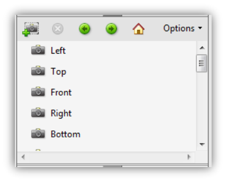
3D Views in Model Tree
Create a custom view
With the Hand tool, click the 3D model to enable it.
Use the Rotate, Pan, and Zoom tools in the 3D toolbar to change the view.
In the Model Tree, hide or show parts, and then click the Create View icon.
In the View Properties dialog box, select the display settings to include in the view.
Note: Properties that are not selected use the settings that were last displayed. For example, if Background Color is not selected, the background color of the view remains the same as the background that was previously displayed.
Note: The view is listed as NewView in the View pane of the Model Tree. Select it to rename it.
Display a view
Use these methods to change the view, as appropriate:
From the 3D toolbar, select the view from the Views pop-up menu.
In the Model Tree, click the view name.
Click the Default View icon.
Change the default view
In the View pane of the Model Tree, do one of the following:
Select a view, and then choose Set as Default View from the Options menu.
Right-click a view, and then choose Set as Default View.
Add a 3D view to a bookmark or link
This process requires a 3D model with one or more defined views, which you can create. You can associate the view with an existing bookmark or link, or you can create a new one for this purpose.
Do one of the following:
To create a new bookmark, click the New Bookmark button at the top of the Bookmarks panel, and type a new name for the bookmark. Then, right-click it and choose Properties.
To create a new link, choose Tools > Edit PDF > Link > Add/Edit Web or Document Link tool, and drag to create a link rectangle anywhere on the page. Then, under Link Action, in the Create Link dialog box, select Custom Link, and click next.
To link a view to an existing bookmark or link, right-click the bookmark or link, and choose Properties.
In the Properties dialog box, click the Actions tab.
From the Select Action menu, choose Go to A 3D/Multimedia View, and then click Add.
In the Select A 3D View dialog box, select the 3D annotation for the 3D model from the list on the left, and then select a view option on the right:
Current View: Matches the 3D rotation, pan, and zoom characteristics that are active in your document at the time you create the link or bookmark, whether or not this view is listed on the Model Tree as a defined view.
First View: Changes to the view that appears at the top of the list in the Model Tree.
Last View: Changes to the view definition that appears at the bottom of the list in the Model Tree.
Previous View: Moves up the Model Tree list of defined views, one view at a time.
Next View: Moves down the Model Tree list of defined views, one view at a time.
Named View: Changes to the defined view that you select from the list appearing below this option.
(Optional) To make a bookmark or link also jump to a specific page and page view, choose Go to a Page View on the Selection Action menu, and click Add. Then use the scroll bars and zoom tools to adjust the page view before you click the Set Link button. When finished, click Close in the Properties dialog box.
Delete a 3D view
Do one of the following:
On the 3D toolbar, open the Views pop-up menu and choose Manage Views. Select the views you want to remove, and click Delete View.
In the View pane of the Model Tree panel, select the views you want to remove. From within the View pane, either click the Delete button or click the Options button and choose Delete View.
3D Preferences
In the 3D & Multimedia panel of the Preferences dialog box, you can determine whether the 3D toolbar and Model Tree are displayed by default. You can also specify a default renderer and determine whether animations are allowed.
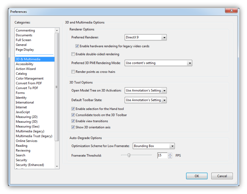
3D Preferences Window
Renderer Options
Preferred Renderer: Specifies the rendering engine used to affect both performance and quality, so it’s important to select the appropriate renderer. Depending on your system, you can change your render engine. If you select a DirectX® or OpenGL option, all rendering takes place using the graphics chip on the video adapter. If Software is selected, rendering takes more time, but the performance is often more consistent with the model rendering of the originating application.
Enable Hardware Rendering For Legacy Video Cards: Forces the use of a hardware accelerator for even video adapters that do not support a pixel shader.
Enable Double-Sided Rendering: Some model parts have two sides. To save time and space, you can deselect this option to render only the side facing the user. If the user looks inside a part rendered with only one side, the back side would be invisible.
Preferred 3D PMI Rendering Mode: Specifies the PMI mode to use for rendering. You can select one of the following options:
Use Content Setting: The rendering of the PMI uses the setting of each PMI to decide whether it uses the Z-buffer.
Always Render 3D PMI In Front Of Model: The rendering of the PMI ignores the Z- buffer regardless of the setting in the file.
Always Render 3D PMI Using Z-buffer: The rendering of the PMI always turns on Z-buffer regardless of the setting in the file.
3D Tool Options
Open Model Tree On 3D Activation: Determines whether the Model Tree is displayed when the 3D model is activated. Choose Use Annotation’s Setting to use whichever setting the author used when adding the 3D model to the PDF.
Default Toolbar State: Determines whether the 3D toolbar is shown or hidden when a 3D model is activated. Choose Use Annotation’s Setting to use whichever setting the author used when adding the 3D model to the PDF.
Enable Selection for the Hand Tool: This allows the user select and highlight parts of the 3D model using the Hand tool. If this option is not selected, use the Object Data tool: Tools > Measure > Object Data Tool.) to select the object.
Consolidate Tools On The 3D Toolbar: Selecting this option places the manipulation and navigation tools under the Rotate tool, thereby shortening the 3D toolbar.
Enable View Transitions: Some 3D models include animated transitions between views. Deselect this option if you want to prevent this 3D animation.
Show 3D Orientation Axis: Turns on or off an in-scene display of an axis that indicates the current orientation of the 3D scene.
Auto Degrade Options
Optimization Scheme for Low Framerate: Specifies what happens to animations of complex models when the framerate becomes low. None does not compromise the visuals and leaves the framerate low. Bounding Box shows the three- dimensional planes enclosing the parts instead of the parts themselves, which keeps the framerate high. Drop Objects does not show some parts of the model, which keeps the framerate high.
Framerate Threshold: Sets the minimum framerate, either by dragging the slider or entering a number in the value box. If the framerate drops below that number of frames per second, the Optimization Scheme for Low Framerate option goes into effect.


Comment on 3D designs
Comments added to a 3D object are associated with specific views that are defined when the comments are added. If the view is changed—for example, if the 3D object is rotated or moved—the comments are no longer visible.
You have three ways to add comments to a 3D object:
Using the 3D Comment Tool on the 3D toolbar to add comments to specific parts of a 3D model.
Using the Comments Tool, Annotations and Drawings to add a variety of comment types to a 3D view.
Converting a 3D measurement into a comment.
Note: When the view of a 3D object is changed, any comment associated with that object disappears (right). If you don’t want a comment to be associated with a 3D view, add the comment outside the 3D object area.
Comments, Markups, Annotations and Drawing in Tetra4D Converter
Add a 3D Comment to an object
Comments created by using the 3D Comment Tool are like measurements in that they are associated with a specific part of the 3D geometry. When you add 3D comments to the default view of a model, a new view, called 3DCommentView is created. 3D comments added to other views are listed as components of that view in the Model Tree. You can edit and remove 3D comments the same way to edit and remove measurements.
When you add comments, a new view is created, allowing you to zoom directly to your comments.
Add comments from the Comment & Markup toolbar
Another way to add comments is to use one of Acrobat’s Annotation tools such as the “Add Text Comment” tool. Similar to adding a 3D comment, this comment will also show up as detail under a view.
Comments, Markups, Annotations and Drawing in Tetra4D Converter
Note: Acrobat Reader users can add comments to a PDF if the document author enables commenting for that PDF.
To add a generic comment in this fashion:
Note: If you delete one of these automatically generated commenting views, the associated comments are still available. You can view and select them in the Comments panel or in the Model Tree, where they are listed under the views. Selecting a comment switches the 3D model to the same viewing configuration it had when the comment was added.
Convert 3D measurements to comments
Individual measurements can be converted to comments, so that they can be reviewed and annotated like other types of comments.
In the View pane of the Model Tree, right-click the plus sign next to the measurement view to display the list of individual measurements.
Right-click a measurement name and click Convert To Comment.
Display comments for a 3D object
Do one of the following:
In the Model Tree, select a view that contains comments.
Choose Tools > Comment.
In the View pane of the Model Tree, click Options and choose List Comments.
Double-click a comment to open its comment window.
Repeat steps 1 and 2 to see other comments associated with other views.
Note: When you select a comment, the 3D model appears in the same view it was in when the comment was added.