3. Traverse CAD Structure
This tutorial guides you through the basics of creating a console application with HOOPS Exchange. By the end of this tutorial, you will have a solid understanding of the technology, allowing you to seamlessly integrate HOOPS Exchange into your own applications.
The completed project will load a specified input file and print the assembly structure to standard output.
Prerequisites
Before you begin, ensure that your environment is correctly configured, please refer to the Environment Setup Guide for detailed instructions.
Source Code: Download the complete source code for this project :
PrintAssemblyStructure.cpp.Replace the code from
samples\exchange\exchangesource\ImportExport\ImportExport.cppwith the one fromPrintAssemblyStructure.cppReplace the input model with
samples\data\catiaV5\CV5_Micro_engine\_micro engine.CATProduct
Your project is now configured and ready for compilation and execution.
Don’t worry, if you have lost the content of the
ImportExport.cppsample you can always download it back fromhere.Build & Run: build the project and run the generated application.
In Visual Studio from the Solution Tree explorer, in Linux & macOS from a command line, build the project and run the generated application.
Tree Structure of a CAD File
Designing a CAD assembly consists of creating detailed 3D models of each individual part using CAD software, precisely defining dimensions, shapes, features, and more. Once the individual components are modeled, they are imported into an assembly workspace. In this workspace, they are positioned and connected accurately using constraints and mates. Individual components can be instantiated and used multiple times.
The CAD file embeds the 3D models and their data, as well as the so-called Model Tree, which contains the structure of the assembly file.
The Model Tree, referred to as A3DTree, is composed of sub-assemblies and sub-parts, called A3DTreeNode.
In this tutorial, we will learn how to traverse and parse this Model Tree to retrieve information stored at each node of the assembly.
Load, Traverse and Get node info
The sample is divided into two parts:
The first focus of this tutorial lies in the latter section, where we traverse the tree structure of a model file to retrieve the entity’s type, name, and color. Following this, we demonstrate the process of loading a CAD file and integrating it with our traversal function.
Get node name
The simplest way to navigate through a CAD file is to use the traversal API that abstracts away the complexity of a model file by using standard tree-structure terminology.
The PrintAssemblyStructure sample comes by default with the code to Import a CAD model and traverse its structure. It recursively visits the child nodes by going deeper into the model tree. This is done by calling A3DTreeNodeGetChildren().
The function gets the child nodes of the currently visited one.
From there, we loop through the list of child nodes and call traverse_tree on each of them.
The traversal is done in a recursive function that is first called on the root node of our model tree:
void traverse_cad_structure(A3DTree* const hnd_tree, A3DTreeNode* const hnd_node, size_t depth) {

     ///User Code to process node///
     //..

     //..
     ///End of process node///

     //Recursively call traverse_cad_structure on child nodes
     A3DUns32 n_child_nodes = 0;
     A3DTreeNode** child_nodes = nullptr;

     if (A3DTreeNodeGetChildren(hnd_tree, hnd_node, &n_child_nodes, &child_nodes) == A3D_SUCCESS) {
             for (A3DUns32 n = 0; n < n_child_nodes; ++n) {
                     traverse_cad_structure(hnd_tree, child_nodes[n], depth + 1);
             }
             A3DTreeNodeGetChildren(0, 0, &n_child_nodes, &child_nodes);
     }
}
The depth parameter is only used to keep in memory the current level of tree traversal. It will be used to provide the indentation while displaying each node name.
The following function is dumping the name of each entity that has been traversed:
// Display node's entity name
std::cout << "Name: ";

A3DUTF8Char* node_name = nullptr;
if (A3DTreeNodeGetName(hnd_node, &node_name) == A3D_SUCCESS && node_name != nullptr) {
        std::cout << node_name << "; ";
        A3DTreeNodeGetName(0, &node_name);
}
else {
        std::cout << "N/A; ";
}
Get node type
If you add this code right after the display node’s entity name function, you will get the type of each entity being traversed as well:
// Display node's entity type
std::cout << "Type: ";

     A3DEntity* pEntity = nullptr;
     A3DTreeNodeGetEntity(hnd_node, &pEntity);
     A3DEEntityType eType = kA3DTypeUnknown;
     if (A3DEntityGetType(pEntity, &eType) == A3D_SUCCESS) {
             const A3DUTF8Char* pTypeMsg = A3DMiscGetEntityTypeMsg(eType);
             std::cout << pTypeMsg << "; ";
     }
     else {
             std::cout << "N/A; ";
     }
Run the application with its default settings. The standard output should display something similar to the following:
Name: Product1; Type: kA3DTypeAsmProductOccurrence
  Name: HOUSING(HOUSING.1); Type: kA3DTypeAsmProductOccurrence
    Name: MechanicalTool.1; Type: kA3DTypeRiBrepModel
    Name: Open_body.1; Type: kA3DTypeRiSet
  Name: CYLINDER LINER(CYLINDER LINER.1); Type: kA3DTypeAsmProductOccurrence
    Name: MechanicalTool.1; Type: kA3DTypeRiSet
      Name: MechanicalTool.1; Type: kA3DTypeRiBrepModel
  Name: HOUSING TOP(HOUSING TOP.1); Type: kA3DTypeAsmProductOccurrence
    Name: MechanicalTool.1; Type: kA3DTypeRiSet
      Name: MechanicalTool.1; Type: kA3DTypeRiBrepModel
  Name: MOBILE PART(MOBILE PART.1); Type: kA3DTypeAsmProductOccurrence
    Name: PUSH ROD(PUSH ROD.1); Type: kA3DTypeAsmProductOccurrence
      Name: MechanicalTool.1; Type: kA3DTypeRiSet
        Name: MechanicalTool.1; Type: kA3DTypeRiBrepModel
...
The output gives you the structure of the assembly file, name, and entity type for each node of the assembly traversed by the function.
Get node color
Now that you have learned how to traverse a model file using A3DTree and A3DTreeNode let’s see how we can retrieve the color of a single part and a part in the context of an assembly.
But first let’s download a set of tests files.
The ZIP files contains two sets of cubes created using CATIA V5:
- Set #1
1_Cube--Asm_1_Cube--Asm_2_Cubescontains: 1 (Part) Cube
1 (Assembly) containing 1 (Part) Cube
1 (Assembly) containing 2 (Parts) Cubes
- Set #2
1_Cube--Asm_1_Cube--Asm_Asm_2_Cubes--Asm_1_Cube_Asm_1_Cube_Asm_2_Cubescontains: 1 (Part) Cube
1 (Assembly) containing 1 (Part) Cube
1 (Assembly) containing 1 (Assembly) containing 2 (Parts) Cubes
1 (Assembly) containing (1 (Part) Cube, 1 (Assembly) containing 1 (Part) Cube, 1 (Assembly) containing 2 (Parts) Cubes
The code below allows you to get the color of each cube. If you have not already done so, simply copy and paste this code after the ‘get name’ and ‘get entity type’ functions:
// Display node's color index
     std::cout << "Color: ";

     A3DGraphStyleData node_style;
     A3D_INITIALIZE_DATA(A3DGraphStyleData, node_style);
     if (A3DTreeNodeGetNetStyle(hnd_node, &node_style) == A3D_SUCCESS)
     {
             A3DGraphRgbColorData color;
             A3D_INITIALIZE_DATA(A3DGraphRgbColorData, color);
             if (A3DGlobalGetGraphRgbColorData(node_style.m_uiRgbColorIndex, &color) == A3D_SUCCESS){
                     std::cout << "RGB(" << color.m_dRed << ";" << color.m_dGreen << ";" << color.m_dBlue << ")";
                     A3DTreeNodeGetNetStyle(0, &node_style);
             }
             else {
                     std::cout << "N/A; ";
             }
     }
Change the test file to use the file CubePart.CATPart from the Set #1 1_Cube--Asm_1_Cube--Asm_2_Cubes instead.
Change in the code the macro #define INPUT_FILE "..." to #define INPUT_FILE "/Cubes/1_Cube--Asm_1_Cube--Asm_2_Cubes/CubePart.CATPart" or use the command line : ImportExport .../CubePart.CATPart .../CubePart.CATPart.prc .../CubePart.CATPart.prc.log.txt
Rebuild and run the application, the application will traverse the structure and will allow you to access to the color (gray : d2d2ff =RGB(0.823529;0.823529;1)) of the cube.
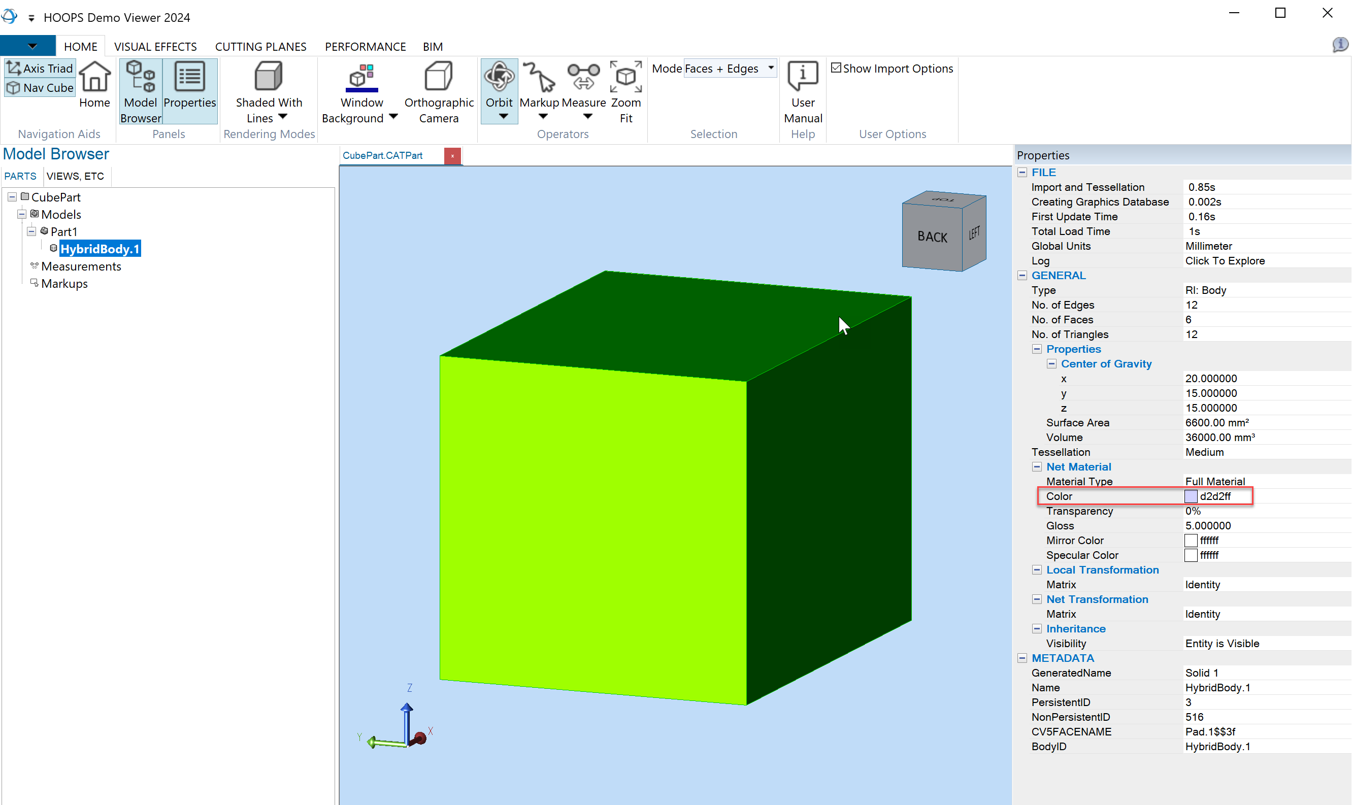
The dump from the sample print assembly structure looks like this:
Name: Part1; Type: kA3DTypeAsmProductOccurrence; Color: N/A;
     Name: HybridBody.1; Type: kA3DTypeRiBrepModel; Color: RGB(0.823529;0.823529;1)

...
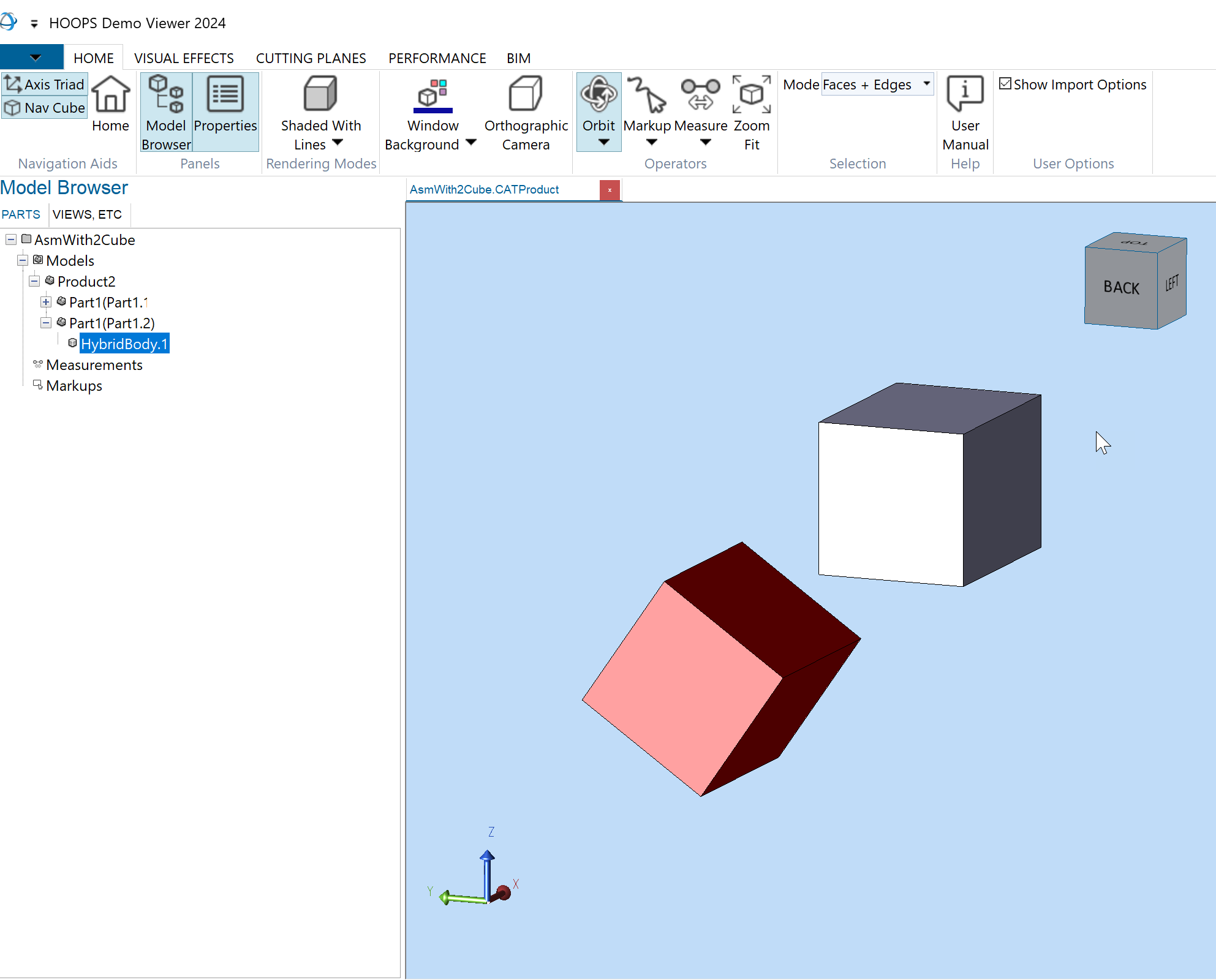
Repeat the same operation with the file AsmWith1Cube.CATProduct and/or AsmWith2Cube.CATProduct and compare the output.
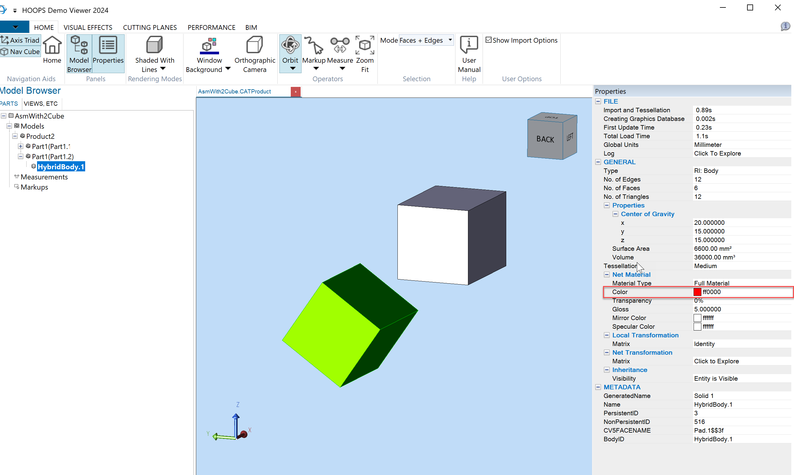
You will now get the colors of the two cubes, the same gray color as before and the one in red.
Name: Product2; Type: kA3DTypeAsmProductOccurrence; Color: N/A;
     Name: Part1(Part1.1); Type: kA3DTypeAsmProductOccurrence; Color: N/A;
  Name: HybridBody.1; Type: kA3DTypeRiBrepModel; Color: RGB(0.823529;0.823529;1)
Name: Part1(Part1.2); Type: kA3DTypeAsmProductOccurrence; Color: RGB(1;0;0)
 Name: HybridBody.1; Type: kA3DTypeRiBrepModel; Color: RGB(1;0;0)

...
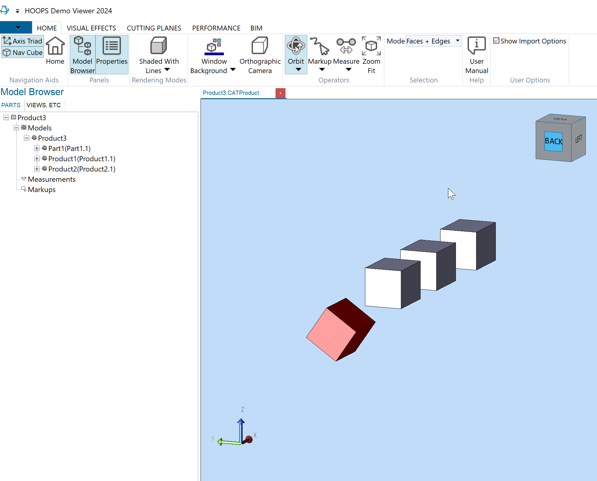
Don’t hesitate to test the other set of test files. The structure is a bit more complex but the process is the same.
If you want to understand more about how colors are stored in a CAD file and available in the HOOPS Exchange PRC structure, please have a look at the Colors and Materials documentation.
Load the CAD file
We have a better idea on how to recursively traverse a model tree, get information at a node level and access the child nodes of the currently visited one.
Let’s now have a look at the Import function and how you instantiate the root A3DTreeNode on which we make our first call of traverse_tree() to traverse the whole CAD structure and interrogate the nodes.
In the main() function, the model file is loaded through the A3DSDKHOOPSExchangeLoader helper class.
After this call, model_file contains a valid handle to your loaded CAD file:
     // ### INITIALIZE HOOPS EXCHANGE
 A3DSDKHOOPSExchangeLoader sHoopsExchangeLoader(_T(HOOPS_BINARY_DIRECTORY));
     CHECK_RET(sHoopsExchangeLoader.m_eSDKStatus);

     CHECK_RET(A3DDllSetCallbacksMemory(CheckMalloc, CheckFree));
     CHECK_RET(A3DDllSetCallbacksReport(PrintLogMessage, PrintLogWarning, PrintLogError));

 // perform Import
     CHECK_RET(sHoopsExchangeLoader.Import(sImport));
...
See sample for more details on the parameters.
Then, we use A3DTreeCompute() to generate the tree structure out of model_file, and A3DTreeGetRootNode() to obtain the root node.
Finally, we call traverse_tree(), that will start the traversal:
//Prepare model tree
A3DTree* hnd_tree = nullptr;
A3DStatus status = A3DTreeCompute(sHoopsExchangeLoader.m_psModelFile, &hnd_tree, nullptr);
assert(status == A3D_SUCCESS);

//Get root node
A3DTreeNode* hnd_root_node = nullptr;
status = A3DTreeGetRootNode(hnd_tree, &hnd_root_node);
assert(status == A3D_SUCCESS);

//Process
traverse_tree(hnd_tree, hnd_root_node, 0);

//free
A3DTreeCompute(nullptr, &hnd_tree, nullptr);

// perform Export
CHECK_RET(sHoopsExchangeLoader.Export(sExport));

//
// ### TERMINATE HOOPS EXCHANGE
//
...
You should have by now a better understanding of how to load a CAD file, traverse its model file, visit and get information on each entity of the structure.
Conclusion
You have now learned how to traverse a model file using A3DTree and A3DTreeNode.
In the next tutorial will understand how to retrieve more advanced information at each levels of the model file structure such as:
The set of transforms that place the object in the 3D space.
Traverse the Tessellation (graphics representation of a part) and the BREP (Boundary-Representation), the geometry defined by the limits of the volume of a CAD part.
Discover how these data can be rendered by many different types of technology like OpenGL, DirectX, Vulkan, Unity, HOOPS visualize…
If you are ready, let’s dive into a more complete example: Write a CAD Viewer.