SolidWorks
This page explains how modifications to parts may affect their persistent ID’s in the Solidworks file format.
In most sections below, you will find two tables.
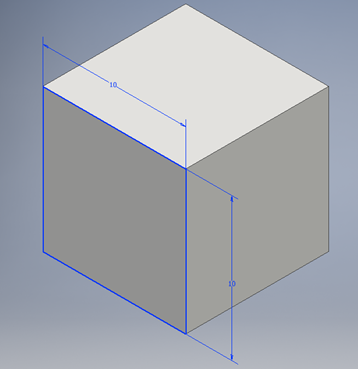
The first set of tables contains two cube images. The left image represents the original, unaltered cube model, while the right image shows the modified instance of the cube model, as described in each section title. The second set of tables provides details on any new or modified persistent ID’s for the model, based on the modified instance described in the section. This includes changes or additions related to faces and edges on the model.
Please note that some sections may not have a second table. However, in these particular cases, context is provided after the initial table.
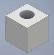
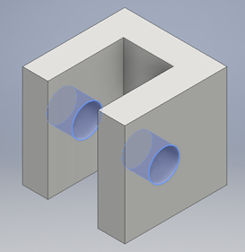
Adding a loop to a face - Extruding a hole into a cube
In this instance, the part was modified by adding a loop to a face. This is the same as extruding a hole into the cube.
| Original Cube Part | Modified Cube Part |
|---|---|
|
|
| Faces | Edges | |
|---|---|---|
| New | 1 face (cylindrical) | 2 edges (see modified image above) |
| Changes | None | None |
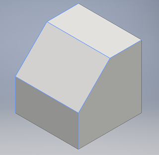
Adding a face to the model - A chamfer
In this instance, the part was modified by adding a face to the model, specifically with a chamfer. A chamfer is a beveled edge that replaces a sharp corner or edge of a part with a sloped surface, typically at a 45-degree angle.
| Original Cube Part | Modified Cube Part |
|---|---|
|
|
|
| Faces | Edges | |
|---|---|---|
| New | 1 face | 4 edges for the chamfer face |
| Changes | None | 1 edge is removed |
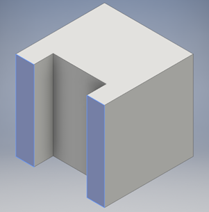
Splitting a face - Adding a groove
In this instance, the part was modified by splitting the a face throughout the model, specifically by adding a uniform groove through the cube, starting from a single face and carrying it through the model’s entirety.
| Original Cube Part | Modified Cube Part |
|---|---|
|
|
|
| Faces | Edges | |
|---|---|---|
| New | 3 faces | 10 edges, for the new faces |
| Changes | 1 face is cut (split) in two. Both have the same persistent ID (see original picture above) | More info coming soon |
Splitting a Cylindrical Surface - Adding a hole through a groove
In this instance, the part was modified by splitting a cylindrical surface through the part that has an existing extrusion. Plainly speaking, this is the same as adding a hole through a groove already existing in the part.
| Original Cube Part | Modified Cube Part |
|---|---|
|
|
|
| Faces | Edges | |
|---|---|---|
| New | 2 faces, with the same persistent ID (see modified image above) | 4 edges |
| Changes | None | None |
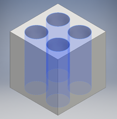
ID Uniqueness - Hole repetition
In this instance, the modified part is considered to have a uniqueness of ID’s. The modification example of multiple unique ID’s is achieved by adding multiple hole extrustions in uniform parallel throughout the cube by a single face.
| Original Cube Part | Modified Cube Part |
|---|---|
|
|
|
A hole repetition (with pattern feature) will create 3 faces, each with different persistent ID’s (1 face per hole).
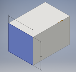
Editing a feature
In this instance, the part was modified by editing a feature. In this particular example, the cube has been transformed into a rectangule.
| Original Cube Part | Modified Cube Part |
|---|---|
|
|
|
Editing a feature does not change any persistent ID.
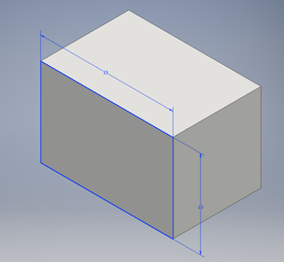
Editing a sketch
In this instance, the part was modified by editing a sketch. In this particular example, the edit was made to the sketch of the cube part model.
| Original Cube Part | Modified Cube Part |
|---|---|
|
|
|
In the SolidWorks file format, editing a sketch will have no effect on the persistent ID’s, if the semantic does not change:
- Editing a segment length does not change any persistent ID’s
- When replacing a segment, any new faces and all associated edges will have new persistent ID’s