cee::ug::ModelSettings
-
class
ModelSettings Various settings for the unstructured grid model.
Public Types
-
enum
UndeformedDrawStyle The draw style to use for the undeformed model.
Values:
-
enumerator
LINES Show undeformed model as lines.
-
enumerator
OUTLINE Show undeformed model as outline.
-
enumerator
-
enum
SimpleTransparencyCullMode Specify if transparent triangles seen from the back side should be rendered or not.
Note: This applies only to simple TransparencyMode::SIMPLE or when using transparent fringes colors.
Values:
-
enumerator
AUTO Try to detect if the part is a closed volume or not. If it is, back face culling is enabled.
-
enumerator
NO_CULLING Draw all transparent triangles.
-
enumerator
BACK_FACE_CULLING Draw only the transparent triangles that has a normal pointing towards the eye.
-
enumerator
-
enum
ModelColorSource Model color source. This will determine how to color each face of the model if no fringes results are used.
Values:
-
enumerator
PART Use part colors (default)
-
enumerator
SET Color element faces by set.
-
enumerator
ELEMENT_TYPE Color element faces by element types.
-
enumerator
USER_PROPERTY_0 Color element faces by the first user property (index 0)
-
enumerator
USER_PROPERTY_1 Color element faces by the second user property (index 1)
-
enumerator
USER_PROPERTY_2 Color element faces by the third user property (index 2)
-
enumerator
Public Functions
-
float
ambientIntensity() const Returns the current ambient intensity (global illumination or normal-independent lighting).
Default is 0.2
-
void
setAmbientIntensity(float intensity) Sets the current ambient intensity (global illumination or normal-independent lighting).
Default is 0.2. A higher value (e.g. 0.8) will make the shaded objects look brighter overall with less shadow effect.
-
bool
showUndeformedModel() const Returns true if the undeformed model will be shown (if displacements are used)
-
void
setShowUndeformedModel(bool show) Specifies to show or hide the undeformed model.
If displacements are used, you can enable this setting to show the original (undisplaced) model as either lines or outline together with the displaced model.
-
UndeformedDrawStyle
undeformedModelDrawStyle() const Returns the current draw style used for the undeformed model.
-
void
setUndeformedModelDrawStyle(UndeformedDrawStyle drawStyle) Sets the draw style to use for the undeformed model.
-
Color3f
undeformedModelColor() const Returns the color that is used for undeformed models, given that the undeformedModelUsePartColor() is false.
-
void
setUndeformedModelColor(Color3f color) Sets the color to use for the undeformed model.
Note that this setting is only used if undeformedModelUsePartColor() is false.
-
bool
undeformedModelUsePartColor() const Returns true if the part color will be used as the color for the undeformed model.
-
void
setUndeformedModelUsePartColor(bool usePartColor) If set to true, the undeformed model will be drawn using the source part color, and not the single color specified by undeformedModelColor().
-
bool
useShaderPrograms() const Returns true if shader programs are used.
-
bool
setUseShaderPrograms(bool useShaderPrograms) Toggles use of shader programs.
The OpenGL context must support shaders to enable this. Also the OpenGL context must support fixed function if you want to disable the use of shaders.
Note: If you disable use of shader programs, only SIMPLE transparency is supported. All the other modes require shader support. See View::setTransparencyMode().
Note: The Qt OpenGL backings (cee::qt::OpenGLFunctionsBackend_qt5) do NOT support fixed function and requires shader usage to be on.
-
bool
useVertexBufferObjects() const Returns true if Vertex Buffer Objects (VBOs) are used (default on).
See also
-
void
setUseVertexBufferObjects(bool useVBOs) Specifies if Vertex Buffer Objects (VBOs) should be used or not.
VBOs are on by default and will then be used if the graphics hardware supports it. This will upload all vertex data to the GPU and thus make the rendering a lot faster.
However, on large models with many time steps and changing vertex data for each step (e.g. displacements), VBOs might cause a performance decrease when the needed VBO memory exceeds the available memory on the graphics card.
So we recommend setting VBOs to false if you are doing large animations with displacements and many time steps.
-
bool
useShaderComputedFlatNormals() const Returns true if shader computed flat normals is used.
See also
setUseShaderComputedFlatNormal
-
void
setUseShaderComputedFlatNormals(bool useShaderComputedNormals) Specifies if shader computed flat normals should be used or not.
If set to true, flat normals will be computed in the fragment shader. This greatly reduces the GPU memory needed to render the model.
Note: This technique has some artifacts when combined with ZOOM navigation. When you zoom into with a large factor the model will start to show a pattern and not smooth colors anymore. This artifact can be avoided by using WALK navigation.
-
bool
useShaderBasedModeShapeAnimation() const Returns true if shader based mode shape animation is enabled.
See also
-
void
setUseShaderBasedModeShapeAnimation(bool useShaderBasedAnimation) Specifies if shader based mode shape animations should be used or not.
If set to true, the node and normal will be computed in the vertex shader based on the displaced and undisplaced geometry. This greatly reduces the GPU memory needed to show the mode shape animation.
-
void
setColorLegendDetailsFont(vis::Font *font) Sets the font to use on the color legend tick marks.
-
Str
colorLegendNoResultOverrideTickMarksText() const Returns the text to show as tick mark values if all parts of the model is out of range.
Returns an empty string if this feature is disabled (default)
-
void
setColorLegendNoResultOverrideTickMarksText(const Str &overrideText) Sets an override text to use for the tick marks on the color legends if there are no results on the model that is within range of the legend.
By setting a non-empty string, the model will be analyzed and the given text will be shown on all tick marks of the color legend if there are no values on the model that is within the range of the legend.
A typical value to set would be “N/A” to indicate that the legend does not apply to the current visualization.
This feature is off by default as the default string is “”.
-
bool
optimizePartRendering() const Returns true if optimization of the rendered parts is enabled.
See also
-
void
setOptimizePartRendering(bool optimize, bool spatiallyPartitionParts = false) Sets if the optimization of rendered parts should be enabled or not.
If set to true, the UnstructGridModel will combine all parts with equal visual appearance (color, draw style, line width, results, etc) into a single part on the graphics card in order to speed up the rendering. This VBO batching will give better and better results as the number of parts increase, and for 20 000+ parts this is essential in order to get good performance.
If spatiallyPartitionParts is set to true, the combined parts will be split into equal chunks of around 21k triangles using a spatial partitioning scheme. If set to false (default) no splitting will be done, only combining.
Note! An UnstructGridModel::updateVisualization(UnstructGridModel::NORMAL) is required after changing this value
-
bool
removeInternalSurfaces() const Returns true if the internal surfaces of a volume element model are removed (default true).
See also
-
void
setRemoveInternalSurfaces(bool removeInternalSurfaces) Sets if the internal surfaces of a volume element model should be removed or not.
The default is true and will give the best performance, as only the surfaces on the hull of the model are rendered.
Set this to false to include inner surfaces if you would like to show something like internal wire frame mode.
-
double
outlineMeshCreaseAngleDegrees() const Returns the current crease angle used to compute outline mesh.
See also
-
void
setOutlineMeshCreaseAngleDegrees(double creaseAngleDegrees) Sets the crease angle to use when computing outline mesh.
Note! An UnstructGridModel::updateVisualization(UnstructGridModel::NORMAL) is required after changing this value
-
double
maximumOutlineMeshCreaseAngleDegrees() const Returns the current maximum crease angle used to compute outline mesh.
-
void
setMaximumOutlineMeshCreaseAngleDegrees(double creaseAngleDegrees) Sets the maximum crease angle to use when computing outline mesh.
This is useful for handling models where surfaces might have opposing normals due to surface winding, but you would not like an outline edge to be shown.
Note! An UnstructGridModel::updateVisualization(UnstructGridModel::NORMAL) is required after changing this value
-
double
smoothSurfaceNormalsCreaseAngleDegrees() const Returns the crease angle used to determine if an edge is a sharp edge or not when computing normals for smooth shading.
-
void
setSmoothSurfaceNormalsCreaseAngleDegrees(double creaseAngleDegrees) Sets the crease angle to use to determine if an edge is a sharp edge or not when computing normals for smooth shading.
Node normals on the edge shared by the two triangles will be averaged unless the angle between the face normal of the two triangles is greater that the specified angle.
Note! An UnstructGridModel::updateVisualization(UnstructGridModel::NORMAL) is required after changing this value.
-
bool
mustBeBehindAllCuttingPlanesToClip() const Returns how clipping against cutting planes will be performed if more than one plane has been specified.
-
void
setMustBeBehindAllCuttingPlanesToClip(bool mustBeBehindAllToClip) Controls how clipping against cutting planes will be done if more than one plane is specified.
Useful for creating “bounded clipping planes” for cutting planes where you define multiple planes in a way that only fragments rejected by all (e.g. inside a box) will be rejected. This allows for “cutting into” a model without removing everything one one side of a plane.
By default an object/fragment will be clipped if it is behind (on the opposite side of the plane normal) at least one of the specified planes. Setting mustBeBehindAllCuttingPlanesToClip to true will require that an object/fragment be behind all the specified planes in order to be clipped.
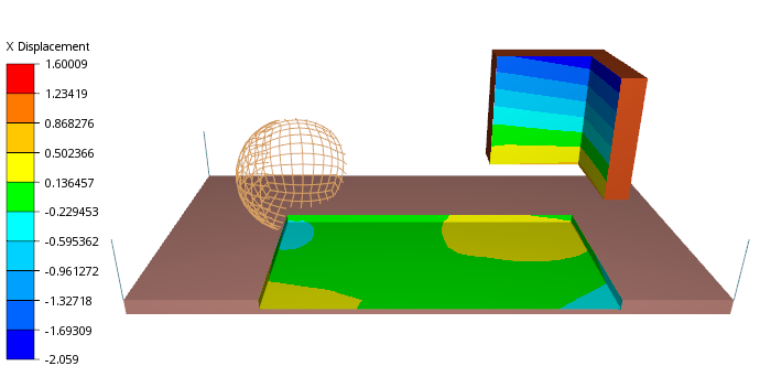
Example
Model with 4 clipping planes defining the bottom, right, back, and left cutting plane with clipping enabled. setMustBeBehindAllCuttingPlanesToClip(true) is used to create bounded clipping planes.
-
bool
isViewClippingIgnored() const Queries if model is configured to ignore view clipping.
-
void
setIgnoreViewClipping(bool ignore) Enables or disable option to ignore view clipping in this model.
-
bool
useFirstOrderElementNodesOnly() const Returns true if first order elements only is used.
-
void
setUseFirstOrderElementNodesOnly(bool useFirstOrderOnly) Sets if first order elements only should be used.
For instance, a quad8 is visualized as quad4, dropping the mid-nodes.
-
ModelColorSource
modelColorSource() const Returns the current model color source. Default: PART (part colors)
-
void
setModelColorSource(ModelColorSource colorSource) Sets the model color source.
This will determine how to color each face of the model if no fringesResults are used. Default is PART (use part colors).
For User Properties, the name of the property and the name of each value that is shown on the legend can be specified in the ElementUserPropertyInfo in the DataSourceDirectory.
-
SimpleTransparencyCullMode
simpleTransparencyCullMode() const Returns the mode used for culling (hiding) triangles in TransparencyMode::SIMPLE or when using transparent fringes colors.
-
void
setSimpleTransparencyCullMode(SimpleTransparencyCullMode mode) Specifies if (auto) back face culling should be used or not when using Simple transparency or when having transparent legend colors.
If set to auto, EnvisionDesktop will try to determine if the object is a closed volume or a shell model. If determined to be a closed volume, back face culling will be enabled.
-
enum