cee::ug::PartSettings
-
class
PartSettings: public RefCountedObject Settings for a specific part.
A part has various settings that can be configured to enhance the visual appearance of your data such as color, draw style and result visibilities.
Each part has its own settings. Get part settings for a specific part by calling UnstructGridModel::partSettings() with the requested geometry index and part id.
int geoIndex = 0;
int partId = 0;
cee::ug::PartSettings* setting = cee::ug::UnstructGridModel::partSettings(geoIndex, partId);
If a setting should be applied to all parts, a part settings iterator is provided for convenience. See PartSettingsIterator.
cee::ug::PartSettingsIterator it(ugModel.get());
while (it.hasNext())
{
    cee::ug::PartSettings* partSettings = it.next();
    partSettings->setFringesVisible(true);
}
Part modes
Part visibility is controlled by the setVisible(). If a part is set invisible, mapped vectors will be set invisible too. If only the vectors should be visible, use setDrawStyle(NONE) instead.
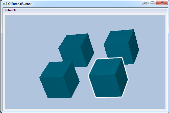
Part highlighting visualizes a white “aura” around each highlighted part. Highlighting is a powerful visual aid in for example part selection. Other objects such as isosurfaces and cutting planes also provides highlighting. Toggle part highlighting with setHighlight()
Appearance
Available draw styles for each part are:
- Surface
- Surface mesh
- Surface outline mesh
- Lines
- Points
- Outline
- Hidden lines removed (Draw hidden lines but remove lines that are obscured by the part itself or other parts)
- None (Don’t draw the part itself but draw vectors mapped on the part)
Set draw style with setDrawStyle() with the preferred enumerated value DrawStyle. Default is Surface draw style. When using draw styles that visualize lines or points, the size and width of these can be adjusted with setLineWidth(), setPointSize() and setMeshLineWidth().
In addition to the above draw styles, you can adjust several attributes such as: part shading (setSmoothShading()), part opacity (setOpacity()), part lighting (setLighting()), part color (setColor()) and even two sided part coloring (setFrontAndBackColor()). The color of a part will not be visible if fringes visibility is toggled on for the part. Part texturing is also supported. Access part settings through textureSettings(). See PartSettingsTexture for available settings.
If areas of parts overlap, the visual priority between these can be set using setEyeLiftFactor() by a factor. This helps prevent rendering artifacts when polygons are drawn directly on top of each other.
Result visibility
Result visibility can be toggled for each result type for each part. Available result visualizations are:
- Scalars Visualize scalars as colored fringes with setFringesVisible(). Fringes colors, legend colors, range and other settings can be adjusted in each results scalar settings.
- Vectors Vector results are visualized as vector arrows when setVectorsVisible() is toggled on. Scaling, vector coloring and other settings can be set in each results vector settings.
- Displacement If displacement visibility is toggled with setDisplacementVisible(), the part nodes will be visualized in their displaced positions. Displacement scaling can be adjusted in the results displacement settings.
A transformation result will always be applied to a part if it is toggled on in the model specification, ModelSpec::setTransformationResult(). Same applies to visibility result (ModelSpec::setVisibilityResult().
Example
This example shows how to apply some different part settings to a model.
The demo file (contact.vtf) contains a geometry with four parts. This tutorial shows how to set the following settings on these parts:
- Part 1: Set invisible
- Part 2: Set color to blue
- Part 3: Set draw style surface mesh
- Part 4: Set transparent
Get the part ids for the four parts in this model. Part info is available in the data sources metadata directory. We know this model only has one geometry and four parts.
std::vector<cee::ug::PartInfo> partInfos = source->directory()->partInfos(0);
int firstPartId = partInfos[0].id();
int secondPartId = partInfos[1].id();
int thirdPartId = partInfos[2].id();
int fourthPartId = partInfos[3].id();
Set the first part invisible
ugModel->partSettings(0, firstPartId)->setVisible(false);
Give the second part the color blue
ugModel->partSettings(0, secondPartId)->setColor(cee::Color3f(0.0, 0.0, 1.0));
Use surface mesh draw style at the third part
ugModel->partSettings(0, thirdPartId)->setDrawStyle(cee::ug::PartSettings::SURFACE_MESH);
Set the fourth part transparent
ugModel->partSettings(0, fourthPartId)->setOpacity(0.5f);
See the complete source code at: UnstructGrid: Apply Part Settings to a Model
See also
UnstructGridModel, ScalarSettings, VectorSettings, and DisplacementSettings
Public Types
-
enum
DrawStyle Part draw styles.
Values:
-
enumerator
SURFACE Draw as surface.
-
enumerator
SURFACE_MESH Draw as surface mesh.
-
enumerator
SURFACE_OUTLINE_MESH Draw as outline mesh
-
enumerator
LINES Draw as lines (wireframe)
-
enumerator
POINTS Draw as points.
-
enumerator
OUTLINE Draw as outline.
-
enumerator
HIDDEN_LINES_REMOVED Draw hidden lines but remove lines that are obscured by the part itself or other parts.
-
enumerator
NONE Don’t draw the part itself (ie still draw vectors mapped on the part)
-
enumerator
Public Functions
-
int
geometryIndex() const Returns true if the part is highlighted.
-
int
partId() const Returns true if the part is highlighted.
-
bool
visible() const Returns true if this part is visible.
-
void
setVisible(bool visible) Toggles part visibility.
-
bool
highlight() const Returns true if the part is highlighted.
-
void
setHighlight(bool showHighlighted) Toggles part highlighting.
-
float
eyeLiftFactor() const Returns the eye lift factor applied to achieve visual priority.
-
void
setEyeLiftFactor(float factor) Sets the eye lift factor applied to achieve visual priority.
-
bool
lighting() const Returns true if the part is rendered with lighting (semi shadowing effect)
-
void
setLighting(bool enable) Enables or disables lighting of the parts.
If disabled, the part will have a constant color independent of the angle of the surface.
-
void
setDrawStyle(DrawStyle drawStyle) Sets the draw style for this object.
Note! Changing the draw style requires an UnstructGridModel::updateVisualization() with updateAction = UnstructGridModel::NORMAL
-
bool
smoothShading() const Returns true if smooth shading is toggled on.
-
void
setSmoothShading(bool enable) Toggles smooth shading.
-
Color3f
color() const Returns the color of the part.
If back and front colors differs, the front color will be returned.
-
void
setColor(const Color3f &color) Sets part color.
This sets both back and front color using the same color. If you want separate back and front colors, use setFrontAndBackColor() instead. Part color will not be visible if fringes visibility is toggled on.
-
void
setFrontAndBackColor(const Color3f &frontColor, const Color3f &backColor) Sets separate front and back colors for the part.
-
float
opacity() const Returns the opacity of the part surface.
1.0 is opaque and 0.0 is fully transparent (invisible)
-
void
setOpacity(float opacity) Sets the opacity of the part surface.
1.0 is opaque and 0.0 is fully transparent (invisible)
-
float
specularIntensity() const Returns the specular intensity set for this part.
-
void
setSpecularIntensity(float intensity) Sets the specular intensity to use for this part.
The specular intensity control the highlight and reflection of the light onto the part. The light is white, so this will cause the color of the part to get more white in the parts that reflect the light source.
Default is 0.5. Legal range is 0.0 -> 1.0, where 0.0 turns off the specular highlight.
-
unsigned int
lineWidth() const Returns line width used for line based draw styles.
-
void
setLineWidth(unsigned int lineWidth) Sets the width of the lines used for line based draw styles.
-
unsigned int
pointSize() const Returns the point size used for point based draw styles.
-
void
setPointSize(unsigned int pointSize) Sets the size of the points used for point based draw styles.
Also applies to parts that contains POINTS elements.
-
unsigned int
meshLineWidth() const Returns line width used for drawing the mesh and outline mesh.
-
void
setMeshLineWidth(unsigned int lineWidth) Sets the width of the lines used for drawing the mesh and outline mesh.
-
bool
fringesVisible() const Returns true if fringes results are visible.
-
void
setFringesVisible(bool visible) Toggles fringes visibility.
Uses the fringes result set in the models model specification (ModelSpec).
-
bool
contourLinesVisible() const Returns true if contour lines are visible.
-
void
setContourLinesVisible(bool visible) Toggles contour lines visibility.
-
bool
vectorsVisible() const Returns true if vector results are visible.
-
void
setVectorsVisible(bool visible) Toggles vector visibility.
Uses the vector results set in the models model specification (ModelSpec).
-
bool
displacementVisible() const Returns true if displacements are visible.
-
void
setDisplacementVisible(bool visible) Toggles displacement visibility.
Uses the displacement result set in the models model specification (ModelSpec).
-
bool
isElementSetFilteringDisabled() const Returns true if element set filtering is disabled for this part.
-
void
disableElementSetFiltering(bool disable) If set to true, this part will not be included in element set filtering.
-
void
setIntersectable(bool intersectable) Sets if the part should be “selectable” or not when doing rayIntersect/regionIntersect.
The default is true. If this is set to false, this part will not be hit by the UnstructGridModels rayIntersect(), regionIntersect() or polygonIntersect() methods.
This is useful if you only want the user to be able to pick/select parts of the model.
-
bool
intersectable() const Returns true if the part is “selectable” (default), i.e.
considered in rayIntersect() or regionIntersect().
If this method returns false, the part will not be hit in UnstructGridModels rayIntersect(), regionIntersect() or polyIntersect().
-
bool
alwaysUsePolygonOffset() const Returns true if Polygon offset will always be used on this part.
-
void
setAlwaysUsePolygonOffset(bool alwaysUse) If set to true, Polygon Offset will always be used when rendering this part.
Polygon offset is used by EnvisionDesktop to render parts with mesh or outline mesh. It is needed to push the geometry slightly backward in order to not conflict visually with the mesh lines.
Use this setting to force polygon offset to be on even if the part does not require it. This might be useful if you have parts with primitives in the same plane and are using eyelift (setEyeLiftFactor) in order to control the visibility of the part. By using polygon offset for surface parts as well as surface mesh/outline mesh parts, the eyelift settings will prevail.
See also
-
void
setPriority(int drawOrderPriority) Sets the drawing order priority of the part.
Parts will be rendered in the given order, with lowest priority first.
To control rendering of parts with elements in the same plane, use the priority to control which part should win (set a high priority to the one that shall win), and then set the depthTestFunction to less or equal (LEQUAL).
Note! drawOrderPriority can maximum be 99999.
See also
-
int
priority() const Returns the drawing order priority of the part.
-
void
setDepthTestFunction(DepthTestFunc depthTestFunction) Sets the depth test function to use when rendering the part.
Default is LESS, which means that the part will be rendered if it is closer to the camera than than the current rendered parts. If two parts are in the same plane, the one will the lowest priority will be rendered first.
If set to less or equal (LEQUAL), the last rendered part will be visible.
To deterministic control the rendering order of different parts with overlapping elements, it is recommended to set the depth test function to LEQUAL and use the part priority to give the part that should be visible a high priority.
See also
-
DepthTestFunc
depthTestFunction() const Returns the depth test function used when rendering the part.
-
void
disableMirroring(bool disable) Sets if this part should be disabled in mirroring of the model.
-
bool
isMirroringDisabled() const Returns true if this part is disabled in model mirroring.
-
void
disableFeatureExtraction(bool disable) Sets if this part should be excluded from any feature extractions, e.g. isovolume.
-
bool
isFeatureExtractionDisabled() const Returns true if this part is excluded from any feature extractions, e.g. isovolume.
-
void
disableExpandElements(bool disable) Disable element expansions.
Element expansion is on by default, but if disable is set to true, all elements (beams) with cross section info will still be shown as lines.
-
bool
isExpandElementsDisabled() const Returns true element expansion (show beam cross section) is disabled for this part.
-
const PartSettingsTexture &
textureSettings() const Returns the texture settings for this part.
-
PartSettingsTexture &
textureSettings() Returns the texture settings for this part.