UnstructGrid: Simple Model with Two Triangles
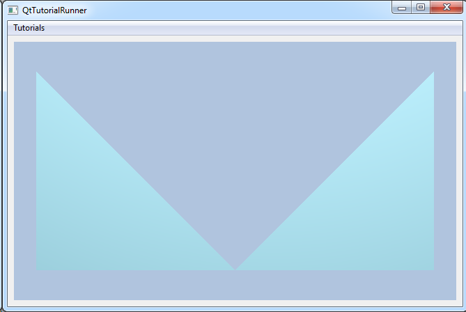
This tutorial shows how to create your own parts and use in a model. The geometry is a very simple structure containing two triangles only.
Note
This example expect the application to have a correctly configured cee::vis::View
in place. See demo applications on how to set up a cee::vis::View in your application.
Create model and data source
Create a model and set a data source.
Since you will be building our own geometry and not read from a file, we use a
cee::ug::DataSourceMemory object.
Upon creation of the cee::ug::DataSourceMemory, you must specify a unique id for this data
source and how many geometries it will contain. Number of geometries cannot be
changed once the data source has been created. In this example you only have one geometry.
    cee::PtrRef<cee::ug::UnstructGridModel> ugModel = new cee::ug::UnstructGridModel();
    cee::PtrRef<cee::ug::DataSourceMemory> dataSource = new cee::ug::DataSourceMemory(1, 1);
    ugModel->setDataSource(dataSource.get());
Create state
Each data source can have many data states. This simple model will only have one state. In the construction of a state, you need to give the state an unique id and set how many geometries it contains.
The number of geometries for a state must always be identical to number of geometries in the data source the state is added to!
Create the state with an id and number of geometries and add it to the data source.
The cee::ug::ModelSpec object is the model specification. Among many other settings, the model
specification tells which state(s) are current. Tell the model specification to use the first (and only)
state.
    int stateId = 1;
    cee::PtrRef<cee::ug::DataState> state = new cee::ug::DataState(stateId, 1);
    dataSource->addState(state.get());
    ugModel->modelSpec().setStateId(stateId);
Create geometry
Create a geometry object and add the geometry to the state at index 0 (since you only have one state).
    int geometryIndex = 0;
    cee::PtrRef<cee::ug::DataGeometry> geo = new cee::ug::DataGeometry();
    state->setGeometry(geometryIndex, geo.get());
Create nodes collection
Create a nodes object. cee::ug::DataNodes is a collection of nodes used for building the part.
In this example you will use 5 nodes to create the two triangles.
Important! The nodes object must be set to the correct size before setting the actual
node coordinates!
    cee::PtrRef<cee::ug::DataNodes> nodes = new cee::ug::DataNodes(false);
    nodes->resize(5);
    nodes->setNode(0, cee::Vec3d(0,1,0));
    nodes->setNode(1, cee::Vec3d(0,0,0));
    nodes->setNode(2, cee::Vec3d(1,0,0));
    nodes->setNode(3, cee::Vec3d(2,0,0));
    nodes->setNode(4, cee::Vec3d(2,1,0));
Create elements
Create the connectivities array for the nodes in the elements. These are specified as one std::vector<unsigned int> for each element. In this example that means two arrays, one for each triangle.
    int c[] = {0, 1, 2, 2, 3, 4};
    std::vector<unsigned int> eltNodes1(c, c+3);    // First triangle
    std::vector<unsigned int> eltNodes2(c+3, c+6);  // Second triangle
Create the elements object. cee::ug::DataElements is a collection of elements used to define
a part. Each element has a element type (here TRIANGLE) and a connectivities array
towards the matching cee::ug::DataNodes object.
Add the two triangle elements.
    nodes->setNode(4, cee::Vec3d(2,1,0));

    // Define elements
    // Connectivity array for two triangles
    int c[] = {0, 1, 2, 2, 3, 4};
    std::vector<unsigned int> eltNodes1(c, c+3);    // First triangle
    std::vector<unsigned int> eltNodes2(c+3, c+6);  // Second triangle

    // Add a triangle to the elements array.
    cee::PtrRef<cee::ug::DataElements> elements = new cee::ug::DataElements(false, 0);
    elements->addElement(cee::ug::Element::TRIANGLES, eltNodes1);
    elements->addElement(cee::ug::Element::TRIANGLES, eltNodes2);
Create the part
Create the DataPart object.
A part consists of:
- Node coordinates (
cee::ug::DataNodes) - Element connectivities (
cee::ug::DataElements)
Set the nodes and elements created above into the part.
    int partId = 1;
    cee::PtrRef<cee::ug::DataPart> part = new cee::ug::DataPart(partId);
    part->setNodes(nodes.get());
    part->setElements(elements.get());
Add the part to the geometry
geo->addPart(part.get());
Set up the created model
When you’re done creating the new data source (or have modified it), you need to populate the directory with the latest changes.
    // Set the part info
    cee::ug::PartInfo partInfo(partId, "My part");
    dataSource->directory()->setPartInfo(geometryIndex, partInfo);

    // Set the state info
    cee::ug::StateInfo stateInfo(stateId, "My state", 0.0);
    dataSource->directory()->setStateInfo(stateInfo);
The model is ready to use and can be added to the view. Exactly where the view exists
depends on the platform and solution. These examples uses Qt and the view is set up
in a cee::qt::ViewerWidget.
    cee::vis::View* gcView = getTutorialView();
    gcView->addModel(ugModel.get());

    ugModel->updateVisualization();
See the complete source code here: