Geometry: Create a Geometry Model
This tutorial shows how to create a geometry model with different parts and effects.
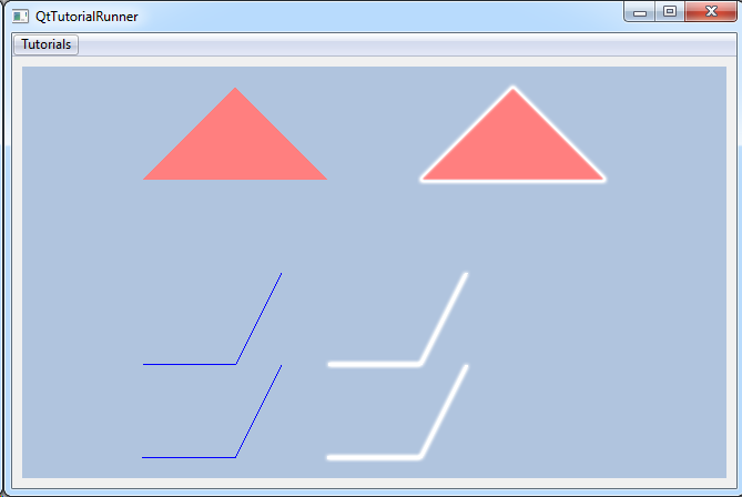
This tutorial creates two triangle parts and two polyline parts. All parts has color effects. The second triangle and the second polyline will have the halo effect applied.
Note
This tutorial expect the application to have a correctly configured cee::vis::View
in place. See demo applications on how to set up a cee::vis::View in your application.
Create model
Create the model and add it to the view.
    cee::PtrRef<cee::geo::GeometryModel> gcgeoModel = new cee::geo::GeometryModel();
    gcView->addModel(gcgeoModel.get());
Set vertices and indices
Create data arrays of vertices and indices for the triangle parts and polyline parts. The second triangle will use the same vertices and indices as the first, but apply a transformation. The two polyline parts will have separate vertices, but share the same array of indices. (They have the same connectivities, but different coordinates.)
    // Triangle vertices and indices
    std::vector<cee::Vec3d> triangleVertices;
    triangleVertices.push_back(cee::Vec3d(0.0, 0.0, 2.0));
    triangleVertices.push_back(cee::Vec3d(2.0, 0.0, 2.0));
    triangleVertices.push_back(cee::Vec3d(1.0, 0.0, 3.0));
    std::vector<unsigned int> triangleIndices = { 0, 1, 2 };

    // First polyline vertices
    std::vector<cee::Vec3d> firstPolylinesVertices;
    firstPolylinesVertices.push_back(cee::Vec3d(0.0, 0.0,  0.0));
    firstPolylinesVertices.push_back(cee::Vec3d(1.0, 0.0,  0.0));
    firstPolylinesVertices.push_back(cee::Vec3d(1.5, 0.0,  1.0));
    firstPolylinesVertices.push_back(cee::Vec3d(0.0, 0.0, -1.0));
    firstPolylinesVertices.push_back(cee::Vec3d(1.0, 0.0, -1.0));
    firstPolylinesVertices.push_back(cee::Vec3d(1.5, 0.0,  0.0));

    // Second polyline vertices
    std::vector<cee::Vec3d> secondPolylinesVertices;
    secondPolylinesVertices.push_back(cee::Vec3d(2.0, 0.0,  0.0));
    secondPolylinesVertices.push_back(cee::Vec3d(3.0, 0.0,  0.0));
    secondPolylinesVertices.push_back(cee::Vec3d(3.5, 0.0,  1.0));
    secondPolylinesVertices.push_back(cee::Vec3d(2.0, 0.0, -1.0));
    secondPolylinesVertices.push_back(cee::Vec3d(3.0, 0.0, -1.0));
    secondPolylinesVertices.push_back(cee::Vec3d(3.5, 0.0,  0.0));

    // Polyline indices
    std::vector<unsigned int> firstLineIndices = { 0, 1, 2 };
    std::vector<unsigned int> secondLineIndices = { 3, 4, 5 };
    std::vector<std::vector<unsigned int> > polylinesIndices;
    polylinesIndices.push_back(firstLineIndices);
    polylinesIndices.push_back(secondLineIndices);
Create part data and build parts
Create a Data for each of the triangles and polylines. The part data binds vertices and
indices and can be used in one or more parts. We only create one part data for triangles, as this will be
used for both triangle parts below.
The triangles will be DataIndexedTriangles objects, while
the polylines will be DataIndexedPolylines objects.
    // Create a triangle data part using the vertices and connectivities
    cee::PtrRef<cee::geo::DataIndexedTriangles> triangleDataPart = new cee::geo::DataIndexedTriangles();
    triangleDataPart->setVertices(triangleVertices);
    triangleDataPart->setIndices(triangleIndices);

    // Create first polyline data part using the vertices and connectivities
    cee::PtrRef<cee::geo::DataIndexedPolylines> firstLinePartData = new cee::geo::DataIndexedPolylines();
    firstLinePartData->setVertices(firstPolylinesVertices);
    firstLinePartData->setPolylinesIndices(polylinesIndices);

    // Create second polyline data part using the vertices and connectivities
    cee::PtrRef<cee::geo::DataIndexedPolylines> secondLinePartData = new cee::geo::DataIndexedPolylines();
    secondLinePartData->setVertices(secondPolylinesVertices);
    secondLinePartData->setPolylinesIndices(polylinesIndices);
Build the parts using the corresponding data parts. Notice that both the triangles uses the same data part, but the second triangle has a transformation to move it to a separate position.
    // First triangle
    cee::PtrRef<cee::geo::Part> trianglePart = new cee::geo::Part();
    trianglePart->setData(triangleDataPart.get());

    // Second triangle (transformed)
    cee::PtrRef<cee::geo::Part> transformedTrianglePart = new cee::geo::Part();
    transformedTrianglePart->setData(triangleDataPart.get());
    transformedTrianglePart->setTransformation(cee::Mat4d::fromTranslation(cee::Vec3d(3.0, 0.0, 0.0)));

    // First polyline
    cee::PtrRef<cee::geo::Part> firstLinePart = new cee::geo::Part();
    firstLinePart->setData(firstLinePartData.get());

    // Second polyline
    cee::PtrRef<cee::geo::Part> secondLinePart = new cee::geo::Part();
    secondLinePart->setData(secondLinePartData.get());
Add effects
In this tutorial we will draw the triangles with the color red. The lines will be colored blue. The second triangle and the second polyline will get a halo effect. The halo effect draws a part with silhouetted edges.
Create the effects:
    // Create a color effect
    cee::PtrRef<cee::geo::EffectColor> triangleColorEffect = new cee::geo::EffectColor();
    triangleColorEffect->setColor(cee::Color3f(1.0f, 0.0f, 0.0f));

    // Create a color effect
    cee::PtrRef<cee::geo::EffectColor> lineColorEffect = new cee::geo::EffectColor();
    lineColorEffect->setColor(cee::Color3f(0.0, 0.0, 1.0));

    // Create a halo effect
    cee::PtrRef<cee::geo::EffectHalo> haloEffect = new cee::geo::EffectHalo();
Add the effects to the parts:
    // First triangle has color effect
    trianglePart->settings().addEffect(triangleColorEffect.get());

    // Second triangle has color and a halo effect
    transformedTrianglePart->settings().addEffect(triangleColorEffect.get());
    transformedTrianglePart->settings().addEffect(haloEffect.get());

    // First polyline has line effect
    firstLinePart->settings().addEffect(lineColorEffect.get());

    // Second polyline has line and halo effect
    secondLinePart->settings().addEffect(lineColorEffect.get());
    secondLinePart->settings().addEffect(haloEffect.get());
We’re done. Add all the parts to the model:
    gcgeoModel->addPart(trianglePart.get());
    gcgeoModel->addPart(transformedTrianglePart.get());
    gcgeoModel->addPart(firstLinePart.get());
    gcgeoModel->addPart(secondLinePart.get());
See the complete source code here: