cee::ug
-
namespace
ug The UnstructGrid component provides functionality for working with unstructured grids.
- Tailored to visualization of scientific data.
- Flexible data structures
- Supports most industry standard element types
- Data extraction (isosurfaces, isovolumes, particle traces and cutting planes)
- Out of the box support for VTFx file format for input/output
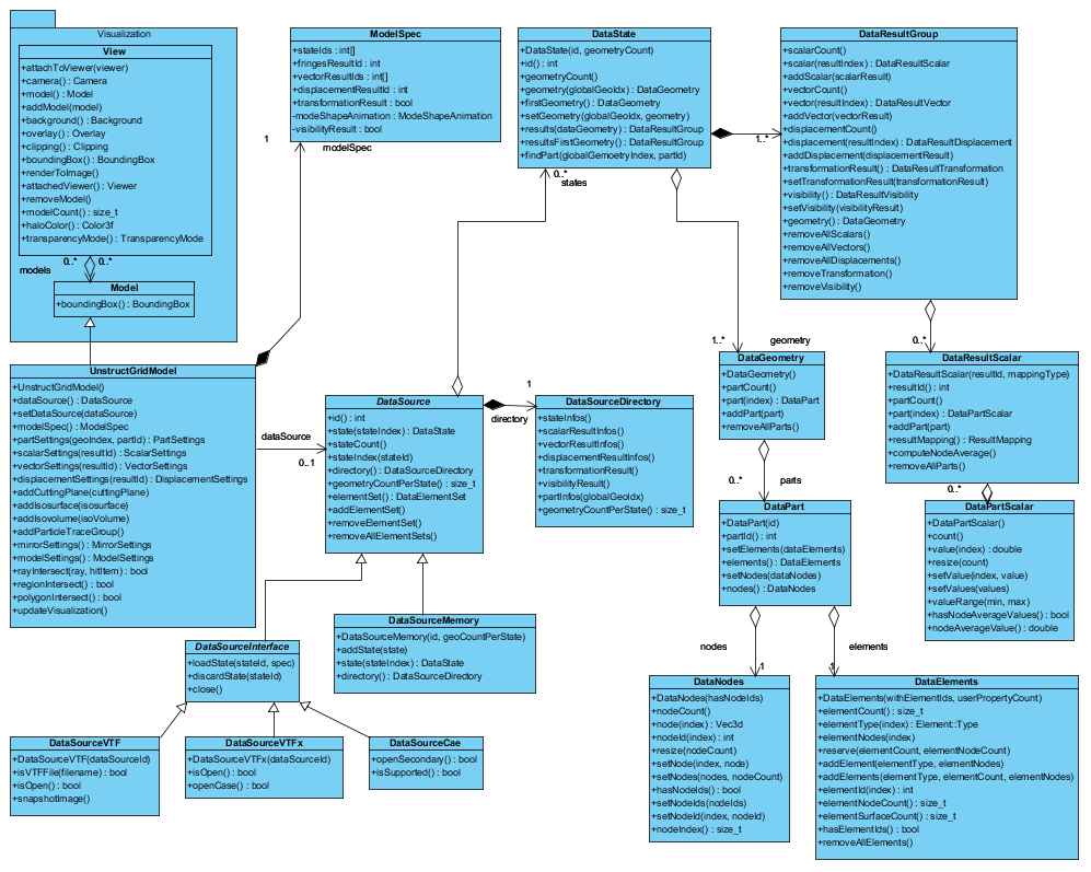
Model holds information which is to be gathered to constitute a view. UnstructGridModel is a subclass of Model which adds specific model structure and functionality for representing scientific and engineering models, e.g. finite element data.
The data model may contain multiple scalar, vector results, displacement results and transformations. The unstructured grid component supports partial results (results available only for a subset of parts).
Result types
- Scalar results
Single result values without orientation. Mapping types are per node, per element, per element node and per element face. Can be shown as both fringes and contour lines.
- Vector results
Results with both a magnitude and spatial direction. Mapping types are per node, per element per element node and per element face.
- Displacement results
Displaced nodes for a given state. All displaced results are mapped per node.
- Rigid body transformation results
All transformation results are per part.
- Visibility results
Result settings
Scalar results can be visualized as contours (fringes). Any number of vector results can be visualized as vector arrows. See ModelSpec on how to setup result visualization in the model specification.
- Scalar settings
The color legend range can be set explicitly or using auto full range using any number of color levels including continuous. A number of color schemes are available (normal, thermal, etc.) Scalar settings also allows scalar filtering. See
ScalarSettings for a complete listing of available scalar settings. - Vector settings
Vectors can be scaled, either absolute or relative to the model. Vector coloring is either single color or colored by fringes. See
VectorSettings for a complete listing of available vector settings. - Displacement settings
A scaling factor can be applies to the visualization of the displacement results. See
DisplacementSettings for further description.
Model parts display settings
The unstructured grid component offers a variety of per part configuration in PartSettings. For instance:
- Part visibility
- Draw styles (surface, surface with mesh, surface with outline mesh, lines, outline, hidden line and points)
- Result visibility (scalars, vectors, displacements, transformation and visibility)
- Highlighting
- Transparency
- Smooth shading
- Part colors with separate front and back colors
- …
Data Extraction
The following features can be extracted by utilizing the functionality in UnstructGridModel:
Cutting planes - cee::ug::CuttingPlane
A cutting plane is a slice through the model onto which can be mapped any scalar and vector fields. This is useful when reviewing results at different locations through the model. The cutting plane is computed based on a point and a normal. See tutorial: UnstructGrid: Create a Cutting Plane with a Scalar Result as Fringes
Isosurfaces - cee::ug::Isosurface
An isosurface is defined as an area with a constant value (e.g. pressure, temperature, velocity, density) within a volume of space. It is the 3D equivalent of a contour line. See tutorial: UnstructGrid: Create an Isosurface
Isovolumes - cee::ug::Isovolume
An isovolume is defined as the combined volume of the element model where the scalar field is between a given minimum and maximum value. The surface of the isovolume will be the hull of this volume See tutorial: UnstructGrid: Create an Isovolume
Particle traces - cee::ug::ParticleTraceGroup
To visualize features of a vector field, it is possible to define streamlines; the paths of massless particles through the flow. A particle trace group is defined by seed points and a vector result. The particle trace can be animated.
Model specification
UnstructGridModel employs a model specification, the ModelSpec class, to specify what to visualize at any given time. ModelSpec enables selection of states (e.g. load cases, time steps, and frequencies), and results (scalar, vector, and displacements).