Geometry: Create a Geometry Model with Geometric Primitives
This tutorial shows how to create a geometry with geometric primitives like spheres, boxes and cylinders.
A geometry model has a part data generator that can be used to tessellate various geometric primitives.
In this tutorial you will create your own geometry model parts and apply some part settings.
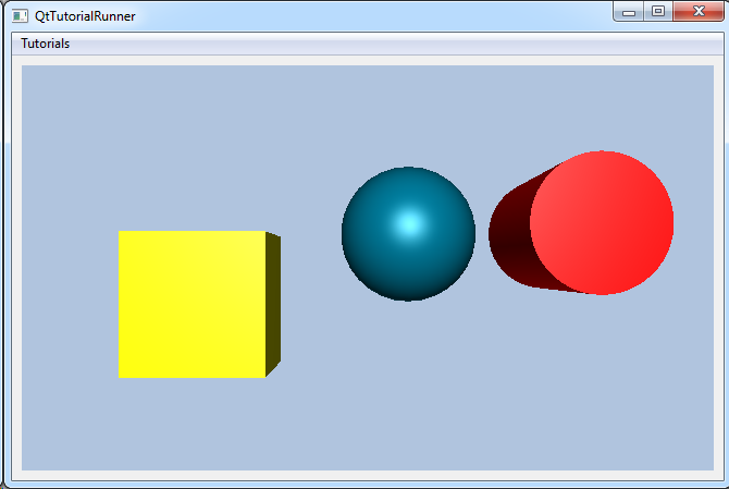
Create the following parts:
- A box
- A sphere
- A cylinder
The box should be colored yellow.
Note
This tutorial expect the application to have a correctly configured cee::vis::View
in place. See demo applications on how to set up a cee::vis::View in your application.
Create the model
cee::PtrRef<cee::geo::GeometryModel> geometryModel = new cee::geo::GeometryModel;
Add the parts
The DataGenerator can tessellate a box and return it as
DataIndexedTriangles. This is fed into the constructor of the
Part.
Add a box part. The box is defined by the center point and the full extent of the box. Then add it to the geometry model.
    cee::PtrRef<cee::geo::Part> boxPart = new cee::geo::Part(cee::geo::DataGenerator::createBox(cee::Vec3d(1.0, 1.0, 1.0), cee::Vec3d(2.0, 2.0, 2.0)).get());
    geometryModel->addPart(boxPart.get());
Add the sphere part. The sphere is defined the center position, the radius of the sphere and the number of subdivisions. Then add it to the geometry model.
    cee::PtrRef<cee::geo::Part> spherePart = new cee::geo::Part(cee::geo::DataGenerator::createSphere(cee::Vec3d(4.0, 2.0, 1.0), 1.0, 30).get());
    geometryModel->addPart(spherePart.get());
Add the cylinder part. The cylinder is defined by the bottom center position, outer and inner radius (no inner radius in this example so it is a full cylinder), the direction of the cylinder and the length (height) and finally the number of sub divisions, which controls the resolution of the tessellation. Then add it to the geometry model.
    cee::PtrRef<cee::geo::Part> cylinderPart = new cee::geo::Part(cee::geo::DataGenerator::createCylinder(cee::Vec3d(6.0, 2.0, 1.0), 0.8, 0.0, cee::Vec3d(0,0,1), 3, 50).get());
    geometryModel->addPart(cylinderPart.get());
Part settings
We use the effect system of the geometry model to control how the parts are visualized. To set the color of the part,
use the PartEffectColor. Below we set the color of the box and cylinder part. The
sphere part is not set and will have the default color as there are no color effects defined on that part.
    boxPart->settings().addEffect(new cee::geo::EffectColor(cee::Color3f(1,1,0)));
    cylinderPart->settings().addEffect(new cee::geo::EffectColor(cee::Color3f(1,0,0)));
Set up the created model
The model is ready to use and can be added to the view. Exactly where the view exists
depends on the platform and solution. These examples uses Qt and the view is set up
in a cee::qt::ViewerWidget.
gcView->addModel(geometryModel.get());
See the complete source code here: