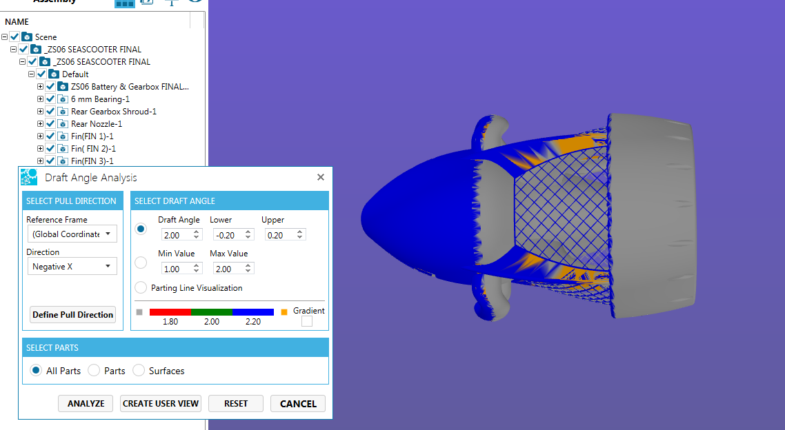
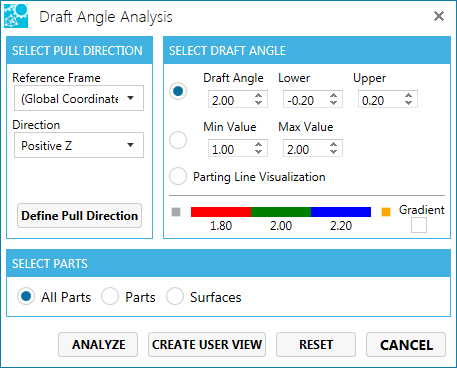
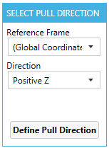
The Pull Direction is defined as the axis against which the angular values specified in the dialog box will be evaluated. By default the Reference Frame selects the World Reference Frame and positive Z direction as the default.
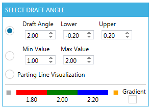
If a new value is selected for the Draft Angle, the scale below the parameter settings changes accordingly.
Limit: Defines the Minimum Value and Maximum Value of draft angle extremes.Min value: This is the lower boundary of the analysis, expressed in degrees of variation from the pull direction, and can be a positive number, negative number, or zero.
Max value: This is the upper boundary of the analysis, expressed in degrees of variation from the pull direction, and can be a positive number, negative number, or zero.
Note: There is no tolerance in this specification as there is in the basic mode.
Gradient: Selection of Gradient specifies a range of deviation from the pull direction, and have the analysis report the results. This option is useful where the effects of a compound surface or a set of surface transitions (such as seen in the blends of a boss with a side wall and a floor of a pocket) need to be analyzed.
Parting Line Visualization: Sets the analysis tolerance to zero. Any surface with non negative (zero or greater) draft will be green while surfaces with negative draft will be red. The partying line is represented by the transition between red and green. Also if there is any red surrounded by green, then there must be some tooling allowance made to accommodate it through the use of slides, lifters or core pins. No geometry is created representing the parting line.Note: When Parting Line Visualization is selected, Gradient option will be grayed out.
Preview Bar:
Preview Bar displays the colors depending upon the value selected in the draft angle, min value and the max value.
Note
To change the color scale double-click on the color component (for Delta and Limit settings, there are three color regions and for Parting Line Visualization, there are two), this displays the dialog box. Choose the desired color and the scale will change accordingly.
This option allows the user to select Parts or Surfaces.
Select Part supports three options:
All Parts: All parts visible in the scene will be analyzed. The default is All Parts.
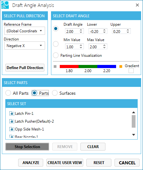
Select Parts: The user can select a part or a set of parts for any single analysis. When this option is selected, the assembly tree is displayed.
** Pick a vertex point on the part in the active workspace.
Pick the part by selecting on the appropriate node in the assembly tree.
Select Surfaces: The user can select a surface or a set of surfaces for any single analysis.
Entity Count: The test box displays the total number of entities selected (parts/ surfaces).
Views
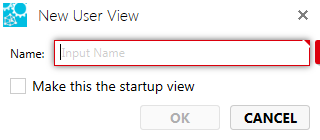
Click Create User View to save the view for further reference.This displays a pop-up.
Enter the View Name.
Click OK to save the view name.
Click Restore View to restore the view without saving the result.
Analyze/ Apply : This button will kick start the analysis based on the user selected “Draft Angleâ€?, “Select Partâ€? options on the selected individual Part(s) or Surface(s). Apply button would initiate the analysis which will change surface colors of the selected parts or surfaces to communicate the Draft Angle Analysis results.
Reset: It would clear any surface or part selections made by the user and would reset the “Entity Countâ€? to zero. The surface analysis colors are reset.
Cancel: It will close the DAA interface and bring the focus back to SpinFire window. The current view orientation will not change. The colors will be reset, unless the user had saved the view.
Conversation saved
SPINNY BETA
Hello! I'm SPINNY
Your multilingual generative AI assistant for documentation. Ask me anything about SpinFire Insight in your own language, or choose a sample question below to start a conversation:
What is SpinFire Insight?
What are the latest release notes for SpinFire Insight?
How do I start evaluating SpinFire Insight?
How can I get assistance?
SPINNY may store conversations according to OpenAI's policy. Responses may not always be accurate.

 ** Pick a vertex point on the part in the active workspace.