
Controlling The View
SpinFire Insight gives you several options for controlling how a model is viewed, but first it is important to distinguish between shifting your view of a scene and moving the contents of the scene itself.
You can think of your view as looking at a model through a remote-controlled camera: rotating, panning, or zooming the point-of-view moves the camera, but the contents of the scene remain stationary.
The focus point of your view and center of rotation will always be at the center of your viewport.
SpinFire Insight also has commands for moving a 3D assembly itself. See Assemblies and Parts in a 3D Scene for more information.
View Features
Rotate, Pan, and Zoom
The commands for manipulating your view of a 2D document are Pan and Zoom. Pan is the default mouse mode for 2D documents.
The basic commands for manipulating your view of a 3D model are Rotate, Pan, and Zoom. Rotate is the default mouse mode for 3D documents. The center of rotation is in the center of the viewport.
See also Keyboard Shortcuts.
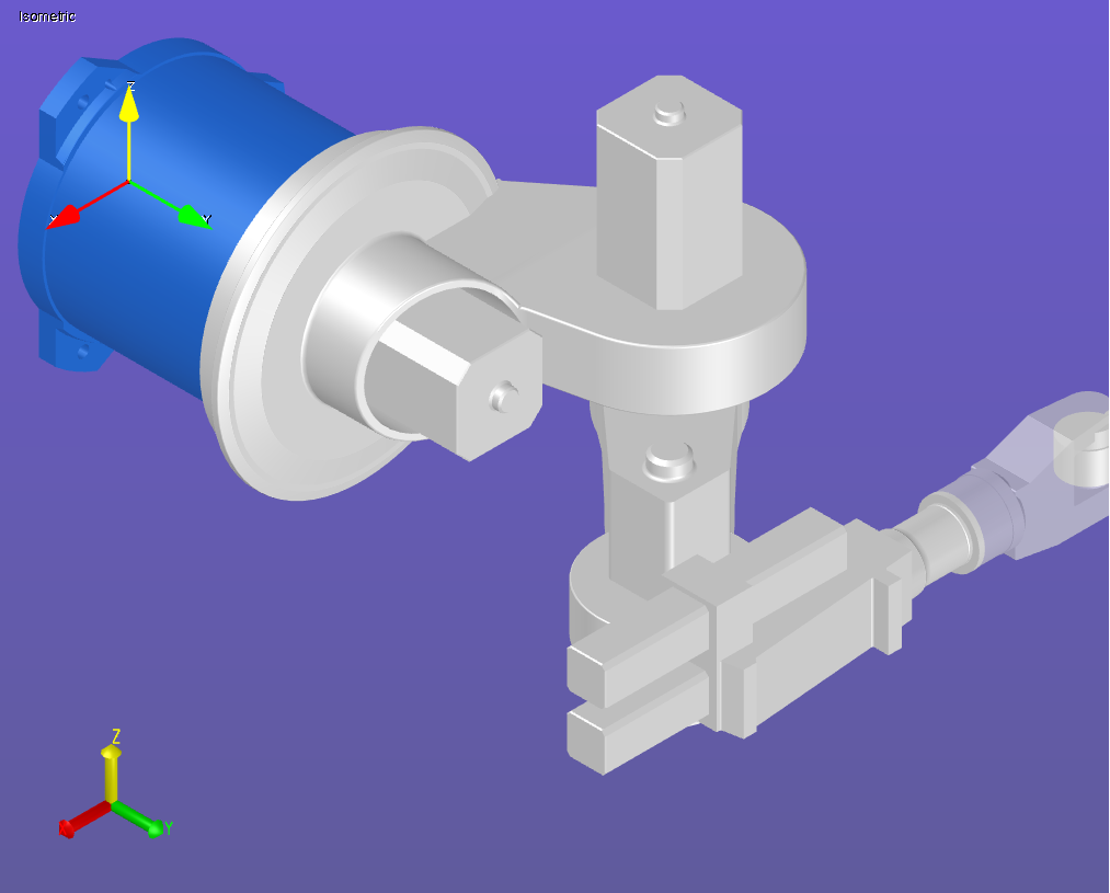
Standard Views
SpinFire Insight provides a set of Standard Views for a 3D scene. Preset camera views (Default, Front, Back, Top, Bottom, Right, Left, Top-Right, Bottom-Right, Bottom-Left, Top-Left) can be selected from the Zoom menu or the Views browser pane.
2D Standard and Cross-Section (if sectioning is enabled) views are accessible from the Views browser pane.
User Views
A user view is a custom view of the 3D scene that has been (named and) saved by a user. User view information is saved in the .ACT3D file. You can add a user view or access saved user views from the Views browser pane. A user view may be selected as the “startup view,” which is displayed when the file is opened.
A user view may consist of just the camera position (user’s point-of-view), or it can also include part rotations and translations that are specific to that particular view. For example, you might perform a rotate or translate command on a part in your assembly and apply that rotation to one of the user views. The part transformation will not be included in the assembly, but will be saved as a named user view.
A user view can include the camera position, geometry information, markups, and cross-section position. (See Working with Views.)
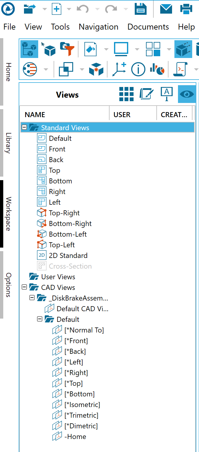
CAD Views
Native CAD files may contain more than one view of the model. SpinFire Insight will import these views and allow you to use them, however, you cannot change or add a new CAD view.
SpinFire Insight creates a Default CAD View that resets the camera to the view of the CAD model when it was initially opened.
Perspective and Parallel Projection
SpinFire Insight uses two kinds of 3D projection to display an assembly: perspective and parallel. Perspective projection displays the model in a realistic manner, the way the object appears to the human eye. This way of drawing, however, can create distortions. Parallel projection maintains an accurate scale for the model—lines remain in proportion, parallel lines remain parallel. Parallel projection is very common in technical drawings and is widely used by mechanical draftsman and engineers. You can switch between perspective and parallel projection by clicking the projection icon in the 3D Document Toolbar.
The default projection option can be set on the 3D Viewer settings page.
Multiple Viewports
4 Viewports - Four equal-sized viewports
2 Horizontal Viewports - Two equal-sized viewports, side-by-side
2 Vertical Viewports - Two equal-sized viewports, one above the other
3+1 Viewports - Three small viewports on the left of the workspace, one large viewport on the right
You can work with the models in each of the viewports just as you normally would. By default, one of the viewports will contain the same view you were viewing, while the other viewports will contain standard views. You can easily resize the viewports by dragging the separation borders with the pointer.
You can set the default projection for the 4 Viewport layout (1st angle or 3rd angle) on the 3D Viewer Settings page.
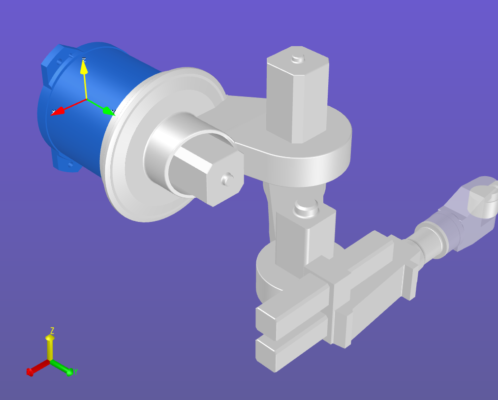
Orientation and Navigation
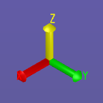
In a 3D scene, a coordinate frame (or axis triad) indicates the origin point (0,0,0) of a coordinate system and the direction of the x-, y-, and z-axes. In SpinFIre, every scene displays the global coordinate system and may contain user-defined coordinate systems as well.
In addition, the navigation cube can help you quickly determine from which perspective you are viewing the model: top, bottom, left, or right.
You can control the default settings for the global coordinate system and the navigation cube on the 3D Viewer Settings page. You can show/hide coordinate systems in a particular scene on the Markups Browser pane.