2D Dimensions
The 2D dimension commands are called from the Linear, Radial, and Angular menus located on the 2D Document Toolbar.
2D Linear Menu
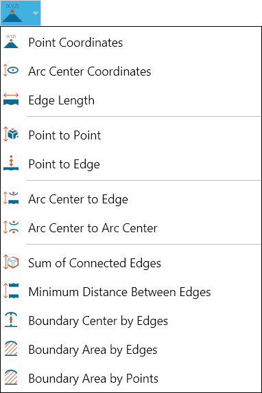
Point Coordinates
Determines the X, Y, and Z coordinates of a point in the drawing. Crosshairs indicate a selectable point.
Arc Center Coordinates
Determines the X, Y, and Z coordinates of the center of an arc in the drawing. The arc is highlighted when the pointer is properly positioned.
Two Edge Intersection Point Coordinates
Finds the projected intersection point of two non-parallel edges.
Edge Length
Measures an existing straight edge in the drawing. The edge is highlighted when the pointer is properly positioned.
Point to Point
Measures the distance between two selected points in the drawing.
You can also choose to measure the distance between two points with respect to the X-, Y-, or Z-axis by selecting the appropriate radio button in the Point to Point dialog box. Right-click a markup to change its properties.
Point to Edge
Measures the distance between a selected point and an edge in the drawing.
Arc Center to Edge
Measures the distance between the center of a selected arc and an edge in the drawing.
Arc Center to Arc Center
Measures the distance between the centers of two selected arcs in the drawing.
Sum of Connected Edges
Calculates the sum of any number of connected edges selected by the user.
Minimum Distance Between Edges
Calculates the shortest distance between two selected edges.
Boundary Center by Edges
Determines the center point of a boundary defined by connected edges. SpinFire Ultimate will automatically find the connected edges that form the boundary and then determine the center point.
You may need to click more than one edge for SpinFire Ultimate to be able to determine the boundary center. For example, if you click an edge on a cube, SpinFire Ultimate will not know which square boundary you want to define. When you click a second edge, SpinFire Ultimate will then be able to calculate the boundary and determine the center point.
Boundary Area by Edges
Calculates the area of a boundary defined by connected edges. SpinFire Ultimate will automatically find the connected edges that form the boundary and then determine the boundary area.
You may need to click more than one edge for SpinFire Ultimate to be able to determine the boundary area. For example, if you click an edge on a cube, SpinFire Ultimate will not know which square boundary you want to define. When you click a second edge, SpinFire Ultimate will then be able to calculate the boundary and determine the area.
Boundary Area by Points
Calculates the area of a boundary defined by three or more selected points.
Linear Measurements
The Linear Menu
Locate point coordinates
Open the Linear menu on the 2D Document Toolbar. (Click the drop-down arrow to the right of the Linear icon to see the menu of commands.)
Select Point Coordinates.
Optional:
Select Lock tool to use the command more than once.
Enter a hyperlink to a file or to a document and user view within the current file.
Position your cursor on the point whose coordinates you want to see and click. (Crosshairs appear when you mouse over a selectable point.)
Drag and click to position the markup in the drawing.
Optional: Click Copy to copy the markup content to the Windows clipboard.
Click Stop when you’re finished taking multiple measurements. Click Close (or X) to end the command and close the dialog box.
Locate coordinates of an arc center
Open the Linear menu on the 2D Document Toolbar. (Click the drop-down arrow to the right of the Linear icon to see the menu of commands.)
Select Arc Center Coordinates.
Optional:
Select Lock tool to use the command more than once.
Enter a hyperlink to a file or to a document and user view within the current file.
Position your pointer over the arc whose center coordinates you want to see and click. (Selectable arcs appear highlighted when you mouse over them.)
Drag and click to position the markup in the drawing.
Optional: Click Copy to copy the markup content to the Windows clipboard.
Click Stop when you’re finished taking multiple measurements. Click Close (or X) to end the command and close the dialog box.
Measure an edge length
Open the Linear menu on the 2D Document Toolbar. (Click the drop-down arrow to the right of the Linear icon to see the menu of commands.)
Select Edge Length.
Optional:
Select Lock tool to use the command more than once.
Enter a hyperlink to a file or to a document and user view within the current file.
Position your pointer over the edge whose length you want to measure and click. (Selectable edges are highlighted when you mouse over them.)
Drag and click to position the markup in the drawing.
Optional: Click Copy to copy the markup content to the Windows clipboard.
Click Stop when you’re finished taking multiple measurements. Click Close (or X) to end the command and close the dialog box.
Measure a distance from point to point
Open the Linear menu on the 2D Document Toolbar. (Click the drop-down arrow to the right of the Linear icon to see the menu of commands.)
Select Point to Point.
Optional:
Select Lock tool to use the command more than once.
Click a radio button to select a measurement axis (the default is Normal).
Enter a hyperlink to a file or to a document and user view within the current file.
Position your cursor on the first point and click. (Crosshairs appear when you mouse over a selectable point.) The selected point is yellow.
Select the end point.
Drag and click to position the markup in the drawing.
Optional: Click Copy to copy the markup content to the Windows clipboard.
Click Stop when you’re finished taking multiple measurements. Click Close (or X) to end the command and close the dialog box.
Measure a distance from point to edge
Open the Linear menu on the 2D Document Toolbar. (Click the drop-down arrow to the right of the Linear icon to see the menu of commands.)
Select Point to Edge.
Optional:
Select Lock tool to use the command more than once.
Click a radio button to select a measurement axis (the default is Normal).
Enter a hyperlink to a file or to a document and user view within the current file.
Position your cursor on the first point and click. (Crosshairs appear when you mouse over a selectable point.) The selected point is yellow.
Select the edge. (Selectable edges are highlighted when you mouse over them.)
Drag and click to position the markup in the drawing.
Optional: Click Copy to copy the markup content to the Windows clipboard.
Click Stop when you’re finished taking multiple measurements. Click Close (or X) to end the command and close the dialog box.
Measure a distance from arc center to edge
Open the Linear menu on the 2D Document Toolbar. (Click the drop-down arrow to the right of the Linear icon to see the menu of commands.)
Select Arc Center to Edge.
Optional:
Select Lock tool to use the command more than once.
Click a radio button to select a measurement axis (the default is Normal).
Enter a hyperlink to a file or to a document and user view within the current file.
Position your cursor on an arc and click. (Selectable arcs are highlighted when you mouse over them.) The selected arc remains highlighted.
Select the edge. (Selectable edges are highlighted when you mouse over them.) The selected edge remains highlighted.
The arc center and the measurement end point appear in yellow. Drag and click to position the markup in the drawing.
Optional: Click Copy to copy the markup content to the Windows clipboard.
Click Stop when you’re finished taking multiple measurements. Click Close (or X) to end the command and close the dialog box.
Measure the distance between two arc centers
Open the Linear menu on the 2D Document Toolbar. (Click the drop-down arrow to the right of the Linear icon to see the menu of commands.)
Select Arc Center to Arc Center.
Optional:
Select Lock tool to use the command more than once.
Click a radio button to select a measurement axis or for the distance between the arcs’ centerlines (the default is Normal).
Enter a hyperlink to a file or to a document and user view within the current file.
Position your cursor on an arc and click. (Selectable arcs are highlighted when you mouse over them.) The selected arc remains highlighted.
Select the second arc.
The arc center points appear in yellow. Drag and click to position the markup in the drawing.
Optional: Click Copy to copy the markup content to the Windows clipboard.
Click Stop when you’re finished taking multiple measurements. Click Close (or X) to end the command and close the dialog box.
Calculate the sum of the lengths of connected edges
Open the Linear menu on the 2D Document Toolbar. (Click the drop-down arrow to the right of the Linear icon to see the menu of commands.)
Select Sum of Connected Edges.
Optional:
Select Lock tool to use the command more than once.
Enter a hyperlink to a file or to a document and user view within the current file.
Position your cursor on an edge and click. (Selectable edges are highlighted when you mouse over them.) The selected edge remains highlighted.
Select the next edge—it must be connected to the first. Continue selecting edges as needed. Double-click the last edge.
The edge and end points are highlighted yellow. Drag and click to position the markup in the drawing.
Optional: Click Copy to copy the markup content to the Windows clipboard.
Click Stop when you’re finished taking multiple measurements. Click Close (or X) to end the command and close the dialog box.
Measure minimum distance between edges
Open the Linear menu on the 2D Document Toolbar. (Click the drop-down arrow to the right of the Linear icon to see the menu of commands.)
Select Minimum Distance Between Edges.
Optional:
Select Lock tool to use the command more than once.
Click a radio button to select a measurement axis (the default is Normal).
Enter a hyperlink to a file or to a document and user view within the current file.
Position your cursor on an edge and click. (Selectable edges are highlighted when you mouse over them.) The selected edge remains highlighted.
Select the second edge.
The measurement end points appear in yellow. Drag and click to position the markup in the drawing.
Optional: Click Copy to copy the markup content to the Windows clipboard.
Click Stop when you’re finished taking multiple measurements. Click Close (or X) to end the command and close the dialog box.
Calculate boundary center by edges
Open the Linear menu on the 2D Document Toolbar. (Click the drop-down arrow to the right of the Linear icon to see the menu of commands.)
Select Boundary Center by Edges.
Optional:
Select Lock tool to use the command more than once.
Enter a hyperlink to a file or to a document and user view within the current file.
Position your cursor on an edge and click. (Selectable edges are highlighted when you mouse over them.) The selected edge remains highlighted.
Continue selecting connected edges until SpinFire determines the intended boundary shape and calculates its center point.
The boundary center point appears in yellow. Drag and click to position the markup in the drawing.
Optional: Click Copy to copy the markup content to the Windows clipboard.
Click Stop when you’re finished taking multiple measurements. Click Close (or X) to end the command and close the dialog box.
Calculate an area by boundary edges
Open the Linear menu on the 2D Document Toolbar. (Click the drop-down arrow to the right of the Linear icon to see the menu of commands.)
Select Boundary Area by Edges.
Optional:
Select Lock tool to use the command more than once.
Enter a hyperlink to a file or to a document and user view within the current file.
Position your cursor on an edge and click. (Selectable edges are highlighted when you mouse over them.) The selected edge remains highlighted.
Continue selecting connected edges until SpinFire determines the intended boundary shape and calculates its area.
The boundary area appears as a highlighted surface. You can hide this surface by right-clicking the markup and choosing Hide Surface.
Drag and click to position the markup in the drawing.
Optional: Click Copy to copy the markup content to the Windows clipboard.
Click Stop when you’re finished taking multiple measurements. Click Close (or X) to end the command and close the dialog box.
Calculate an area by boundary points
Open the Linear menu on the 2D Document Toolbar. (Click the drop-down arrow to the right of the Linear icon to see the menu of commands.)
Select Boundary Area by Points.
Optional:
Select Lock tool to use the command more than once.
Enter a hyperlink to a file or to a document and user view within the current file.
Position your cursor on the first point and click. (Crosshairs appear when you mouse over a selectable point.) The selected point is yellow.
Continue selecting points as needed. Double-click the last point.
Drag and click to position the markup in the drawing.
Optional: Click Copy to copy the markup content to the Windows clipboard.
Click Stop when you’re finished taking multiple measurements. Click Close (or X) to end the command and close the dialog box.
Using Smart Dimension to measure an edge
Click the Smart Edge Dimension icon on the 2D Document Toolbar.

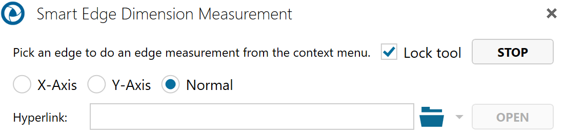
Mouse over and select a highlighted edge.
Optional:
Select Lock tool to use the command more than once.
Enter a hyperlink to a file or to a document and user view within the current file.
Position your cursor on an edge. (Selectable edges are highlighted when you mouse over them.)
Double-click the left mouse button to measure the edge length (default).
Or click the right mouse button to bring up a context menu containing additional measurement options, then make your selection.
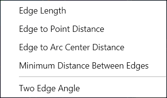
If the edge you select is an arc, the context menu will contain more measurement choices.
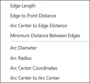
Drag and click to position the label in the scene.
Note
If you want to add several of the same type of markup, you may select the Lock tool checkbox that appears when you select a markup command. This will allow you to keep adding the same type of markup to the scene until you click Stop.
2D Radial Menu
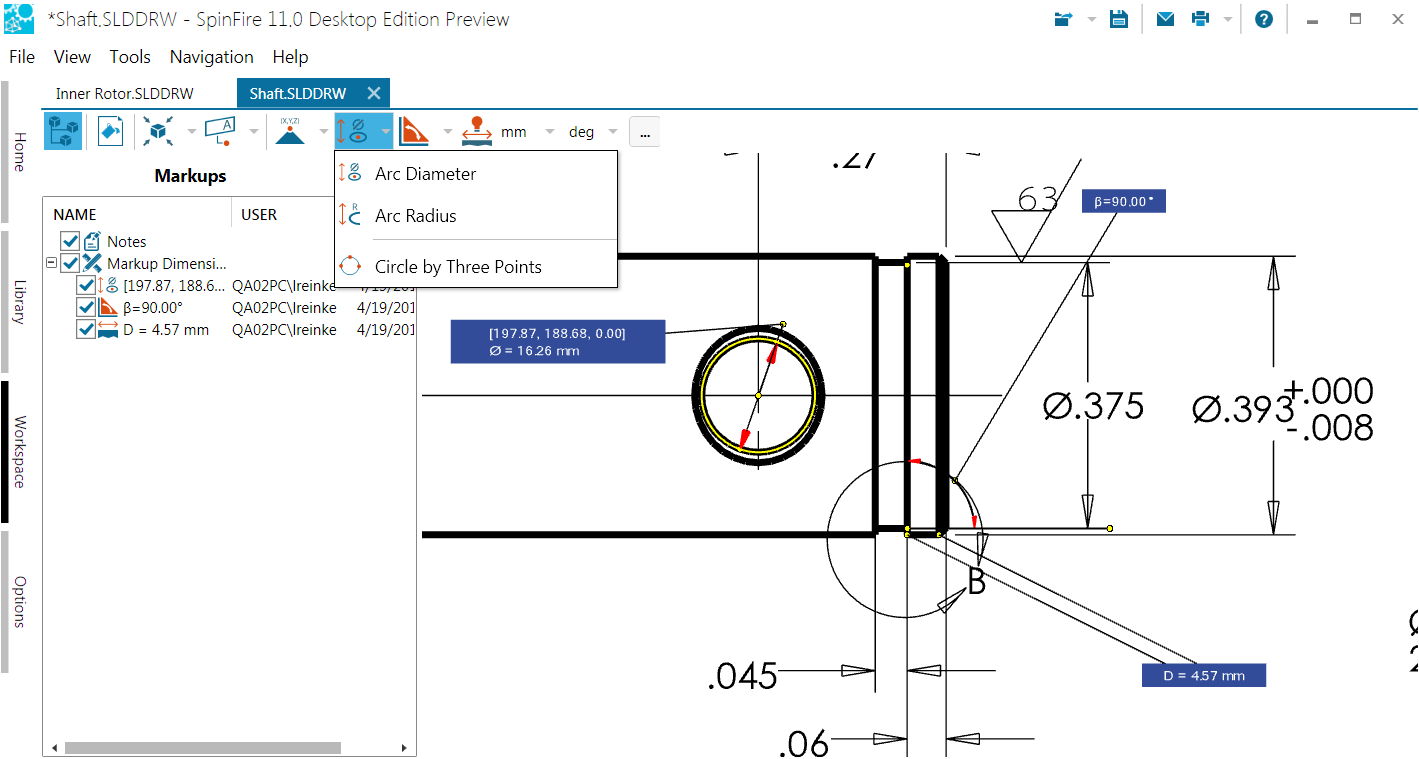
Arc Diameter
Measures the diameter of a circle derived from a selected arc in the drawing. The markup displays the center point coordinates and length of the diameter of the derived circle.
Arc Radius
Measures the radius of a circle derived from a selected arc in the drawing. The markup displays the center point coordinates and length of the radius of the derived circle.
Circle by Three Points
Draws a visible circle that passes through three selected points in the drawing and determines the diameter of the circle. The diameter line is drawn through the first point you selected. The markup displays the diameter length and center point coordinates of the circle.
Radial Measurements
The Radial Menu
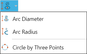
Measure an arc diameter
Open the Radial menu on the 2D Document Toolbar. (Click the drop-down arrow to the right of the Radial icon to see the menu of commands.)
Select Arc Diameter.
Optional:
Select Lock tool to use the command more than once.
Choose to show/hide the arc center point coordinates (the default is Show).
Enter a hyperlink to a file or to a document and user view within the current file.
Position your cursor on an edge and click. (Selectable edges are highlighted when you mouse over them.) The selected edge remains highlighted in yellow.
Drag and click to position the markup in the drawing.
Optional: Click Copy to copy the markup content to the Windows clipboard.
Click Stop when you’re finished taking multiple measurements. Click Close (or X) to end the command and close the dialog box.
Measure an arc radius
Open the Radial menu on the 2D Document Toolbar. (Click the drop-down arrow to the right of the Radial icon to see the menu of commands.)
Select Arc Radius.
Optional:
Select Lock tool to use the command more than once.
Choose to show/hide the arc center point coordinates (the default is Show).
Enter a hyperlink to a file or to a document and user view within the current file.
Position your cursor on an edge and click. (Selectable edges are highlighted when you mouse over them.) The selected edge remains highlighted in yellow.
Drag and click to position the markup in the drawing.
Optional: Click Copy to copy the markup content to the Windows clipboard.
Click Stop when you’re finished taking multiple measurements. Click Close (or X) to end the command and close the dialog box.
Measure a circle defined by three points
Open the Radial menu on the 2D Document Toolbar. (Click the drop-down arrow to the right of the Radial icon to see the menu of commands.)
Select Circle by Three Points.
Optional:
Select Lock tool to use the command more than once.
Choose to show/hide the arc center point coordinates (the default is Show).
Enter a hyperlink to a file or to a document and user view within the current file.
Position your cursor on the first point and click. (Crosshairs appear when you mouse over a selectable point.) The selected point is yellow.
Continue selecting the next two points. The resulting circle is drawn in yellow, and the markup contains the center point coordinates and diameter length.
Drag and click to position the markup in the drawing.
Optional: Click Copy to copy the markup content to the Windows clipboard.
Click Stop when you’re finished taking multiple measurements. Click Close (or X) to end the command and close the dialog box.
2D Angular Menu
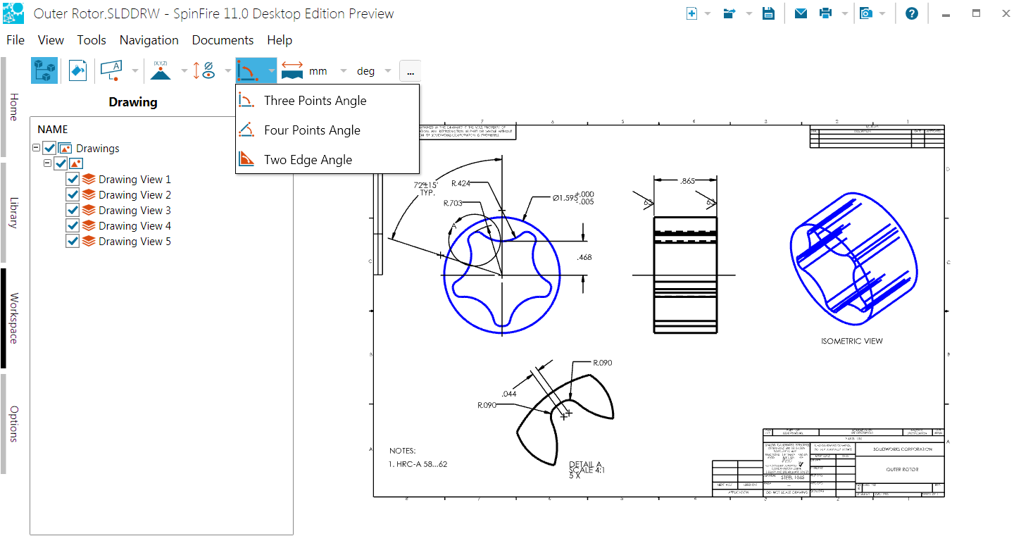
Three Points Angle
Measures an angle defined by two segments with a common point. The second point you select will be the vertex of the angle.
Once the markup label is displayed, you can also determine the reflex angle by using the Flip Axis command on the markup context menu.
See Angular Measurements for how to use this command, and 2D Document Functions for the context menu.
Four Points Angle
Measures an angle defined by two segments with a common point. The first point you select will be the vertex of the angle.
Once the markup label is displayed, you can also determine the reflex angle by using the Flip Axis command on the markup context menu.
See Angular Measurements for how to use this command, and 2D Document Functions for the context menu.
Two Edge Angle
Measures an angle defined by two connected straight edges.
Once the markup label is displayed, you can also determine the reflex angle by using the Flip Axis command on the markup context menu.
See Angular Measurements for how to use this command, and 2D Document Functions for the context menu.
Angular Measurements
The Angular Menu
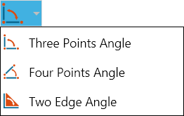
Measure an angle defined by three points
Open the Angular menu on the 2D Document Toolbar. (Click the drop-down arrow to the right of the Angular icon to see the menu of commands.)
Select Three Points Angle.
Optional:
Select Lock tool to use the command more than once.
Enter a hyperlink to a file or to a document and user view within the current file.
Position your cursor on the first point and click. (Crosshairs appear when you mouse over a selectable point.) The selected point is yellow.
Select the second and third points. The second point will be the vertex point of the angle.
Drag and click to position the markup in the drawing.
Optional: Click Copy to copy the markup content to the Windows clipboard.
Click Stop when you’re finished taking multiple measurements. Click Close (or X) to end the command and close the dialog box.
Note
Once the markup label is displayed, you can also determine the reflex angle by using the Flip Axis command on the markup context menu. See Working with 2D Markups for information on using this command and the context menu.
Measure an angle defined by four points
Open the Angular menu on the 2D Document Toolbar. (Click the drop-down arrow to the right of the Angular icon to see the menu of commands.)
Select Four Points Angle.
Optional:
Select Lock tool to use the command more than once.
Enter a hyperlink to a file or to a document and user view within the current file.
Position your cursor on the first point and click, then select the second point. (Crosshairs appear when you mouse over a selectable point. A selected point is yellow.) These two selections define the first side of the angle.
Select the third and fourth points. These selections define the second side of the angle, which SpinFire extends to intersect with the first side.
Drag and click to position the markup in the drawing.
Optional: Click Copy to copy the markup content to the Windows clipboard.
Click Stop when you’re finished taking multiple measurements. Click Close (or X) to end the command and close the dialog box.
Note
Once the markup label is displayed, you can also determine the reflex angle by using the Flip Axis command on the markup context menu. See Working with 2D Markups for information on using this command and the context menu.
Measuring a two-edge angle
Open the Angular menu on the 2D Document Toolbar. (Click the drop-down arrow to the right of the Angular icon to see the menu of commands.)
Select Two Edge Angle.
Optional:
Select Lock tool to use the command more than once.
Enter a hyperlink to a file or to a document and user view within the current file.
Position your cursor on the first edge and click. (Selectable edges are highlighted when you mouse over them.)
Select the second edge.
Drag and click to position the markup in the drawing.
Optional: Click Copy to copy the markup content to the Windows clipboard.
Click Stop when you’re finished taking multiple measurements. Click Close (or X) to end the command and close the dialog box.
Note
Once the markup label is displayed, you can also determine the reflex angle by using the Flip Axis command on the markup context menu. See Working with 2D Markups for information on using this command and the context menu.