
Stream Cache Workflows
This document outlines the different workflows and methods of storing and accessing the Stream Cache representation of a CAD assembly.
Monolithic
In monolithic mode, a CAD assembly is represented as a single Stream Cache Model. The tessellated geometry, the assembly tree and all non-tessellation related data (PMI, measurement data, views, user attributes, etc.) are stored within this single model. Depending on various Viewer settings, certain data within the Stream Cache Model will reside on the server and may be requested “on-demand” (for example, user attributes), while mesh data is usually streamed in a prioritized fashion based on the current camera. Depending on the stream mode, geometry with a “hidden” default state might not stream to the client until the mesh becomes visible.
A Stream Cache Model can be written as an SCS (Stream Cache Single) file, which is a standalone, non-streamable single-file version of the Stream Cache Model. Using models in this format does not require the Stream Cache Server and can either be served from any standard web server or loaded directly from the local file system.
Converter example:
converter --input "cadassembly.CATProduct" --output_sc "mymodels\cadassembly" // creates a single SC model directory
Shattered
Shattered mode refers to the ability to split a CAD Assembly into separate files and (largely) retain its original hierarchy. This approach to storing CAD data allows for updating of individual components of a larger Model without having to reconvert the whole Assembly.
Creating the Shattered Parts
The first step is to use Converter to build a Stream Cache (SC) model file for each part of the assembly and an XML file containing its structure. By providing an output directory for the converted parts with the --prepare_shattered_parts command-line option, the resulting SC model parts will be stored with the native CAD part filenames. To avoid naming conflicts, the relative path from the head of the assembly to the filename is appended.
The XML referencing the SC part is created by specifying --prepare_shattered_xml. The generated XML
file contains the assembly structure which references the SC model parts and will use an “external model” markup to specify those dependencies. While the XML file is created for you
when importing a CAD Assembly via Converter in most real-world scenarios, this file would have to be generated by the customer based on the desired configuration of the assembly.
<pre>
<ProductOccurence Id="7" Name="" Behaviour="1" IsPart="false">
        <ExternalModel Name="Cube.par"/>
</ProductOccurence>
</pre>
In this example “Cube.par” is the name of the native CAD part, and becomes the name of the generated SC model part.
Creating a Master SC Model
To view a shattered assembly created via the process above we need to create the SC equivalent of the XML file generated in that process. To accomplish this, Converter needs to be called with the following options:
--sc_shattered_parts_directory: Directory containing the SC part models.--input_xml_shattered: Path to XML file.--output_sc_master: Name of the master SC model.
NOTE: The master SC model will only contain links to its external model dependencies - there is no need to rebuild the master SC model if the content of the external models changes.
Additional Use Cases
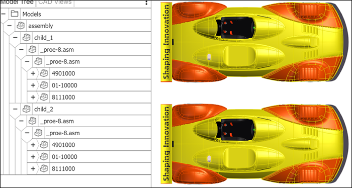
An external model link can point to a full monolithic assembly SC model. In the example below, a full car assembly that was converted to a monolithic SC model called “car” is referenced in the XML file via an external link.
<Root>
        <ModelFile>
                <ProductOccurence Id="0" Name="assembly" Behaviour="1" Children="1 2"/>
                <ProductOccurence Id="1" Name="child_1" Behaviour="1">
                        <ExternalModel Name="car"/>
                </ProductOccurence>
                <ProductOccurence Id="2" Name="child_2" Behaviour="1">
                        <Transformation RelativeTransfo="1 0 0 0 0 1 0 0 0 0 1 0 0 -100 0 1"/>
                        <ExternalModel Name="car"/>
                </ProductOccurence>
        </ModelFile>
</Root>
You should get the following output:
Known Limitations
Per-Instance Coloring
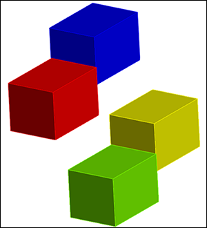
One current limitation of the shattered assembly approach is the handling of per-instance colors. In the example below, a model consists of four cubes, each one an instance of the same part but with a different color. In shattered mode, however, the four cubes are all the same color.
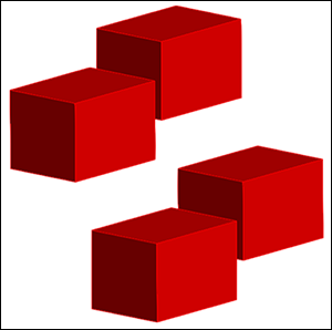
This limitation currently exists only when using different materials on multiple instances. If materials are set within the assembly and only affect a single part, then the behavior will be correct. When we build the shattered parts we bake the fully resolved materials into each part, resulting in the same materials applied to multiple instances. We plan on improving this behavior in an upcoming release of HOOPS Visualize Web.
Assembly Features
Assembly-level features in shattered mode are supported. Converter will automatically generate additional stream cache models for each occurrence of a part where assembly level features are applied. You will notice additional sub-folders are created for nodes containing features. The naming convention is based on the original part name combined with the referencing assembly that contains the feature. An index is used to ensure filenames and references are unique.