Cutting Planes
Basic Concepts
Cutting planes are used to hide geometry on one side of a plane. Multiple cutting planes can be added to the scene to create a view that shows only part of the model. Cutting planes are contained in cutting sections.
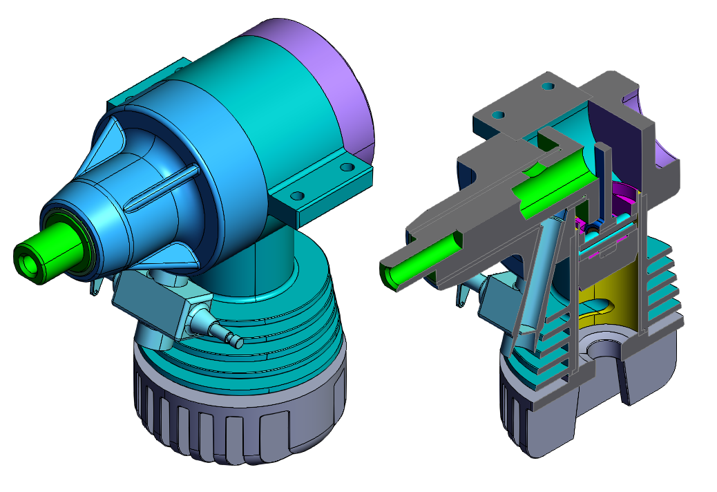
Cutting plane example
Cutting Manager
The CuttingManager controls the logic of creating cutting sections and cutting planes.
Cutting Sections
There is a max of 6 cutting sections. Each cutting section may contain up to 4 cutting planes. Cutting planes in separate cutting sections cut independently. If any cutting section cuts the geometry, the geometry is hidden. Within a cutting section, each cutting plane must cut the geometry to hide it.
        const bounding = await hwv.model.getModelBounding(true, true);
        const axis = Communicator.Axis.X;
        const position = bounding.min;

        const referenceGeometry = hwv.cuttingManager.createReferenceGeometryFromAxis(
            axis,
            bounding,
        );
        const plane = Communicator.Plane.createFromPointAndNormal(
            position,
            new Communicator.Point3(1, 0, 0),
        );

        const cuttingSection = hwv.cuttingManager.getCuttingSection(0);
        cuttingSection.addPlane(plane, referenceGeometry);

        await cuttingSection.activate();
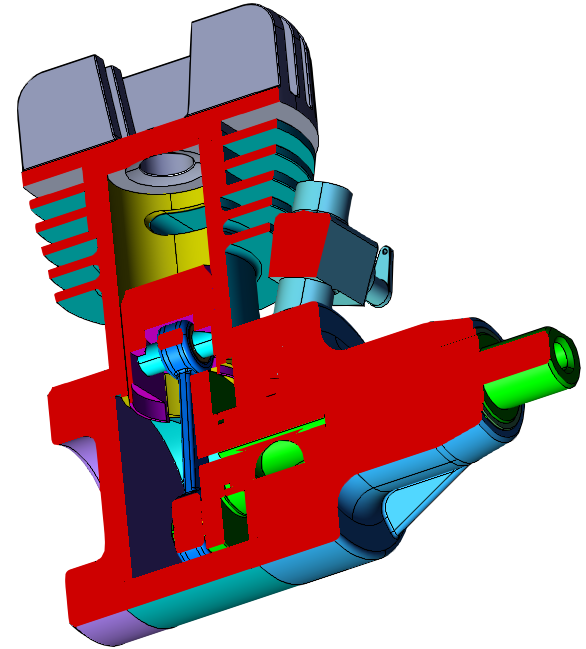
Capping Geometry
When a part is cut by a plane, capping geometry can be drawn to close the shape. If the cutting plane is moved, the capping geometry will be updated. Capping geometry is optional. Visibility and color can be set separately for both faces and lines. Capping geometry settings are the same across all cutting sections.
    // show capping geometry
    hwv.cuttingManager.setCappingGeometryVisibility(true);

    // set face color to red
    hwv.cuttingManager.setCappingFaceColor(Communicator.Color.red());

    // hide capping geometry lines
    hwv.cuttingManager.setCappingLineColor(null);
Reference Geometry
Stand in geometry represents the location of the cutting plane. Reference geometry is optional and can be configured for each cutting plane. The geometry is specified with 4 world space coordinates which are used to draw a transparent plane representation. The coordinates that define the reference geometry should be specified in a clockwise or counterclockwise fashion, and define a plane that contains the origin.
The cutting manager has two functions to generate coordinates for the reference geometry.
createReferenceGeometryFromAxis uses the provided bounding box to create reference geometry coordinates at the edge of the box aligned with the provided axis.
createReferenceGeometryFromFaceNormal creates reference geometry coordinates aligned with the normal, at the position, using the bounding box as guidance for the rectangle size.
        const bounding = await hwv.model.getModelBounding(true, true);
        const axis = Communicator.Axis.X;
        const normal = new Communicator.Point3(1, 0, 0);
        const position = Communicator.Point3.zero();

        const axisReferenceGeometry = hwv.cuttingManager.createReferenceGeometryFromAxis(
            axis,
            bounding,
        );
        const faceReferenceGeometry = hwv.cuttingManager.createReferenceGeometryFromFaceNormal(
            normal,
            position,
            bounding,
        );
Cutting Plane Operator
The cutting plane operator interacts with cutting plane reference geometry to move the cutting planes. If a cutting plane has reference geometry visible, the cutting plane operator will move the reference geometry when it is selected with a mouse (or touch input) drag.
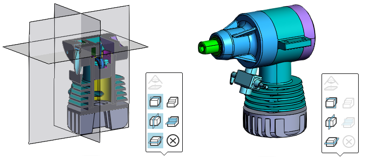
Cutting Pane UI
The HOOPS Visualize Web UI has controls for adding and removing cutting planes. The UI assumes that nothing else is changing the state of cutting planes simultaneously. If changes are made to cutting planes using the API, the icon state of the UI may become out of sync.
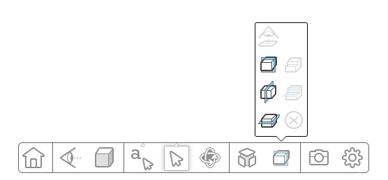
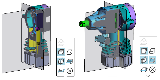
The left column has 4 icons for inserting cutting planes. The bottom 3 add a cutting plane along the X, Y, or Z axis. The top icon aligns a cutting plane to a face normal. When there is no plane selected, the icon is disabled. Selecting a face will enable the icon.
When a cutting plane is added, the background color for the icon will change to light blue. Clicking on an icon when it is light blue changes inverts the direction of the cutting plane and changes the background of the icon to dark blue. Clicking on the icon again will remove the cutting plane.
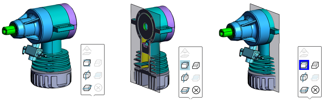
The top icon in the right column toggles the visibility of the cutting plane reference geometry. By default, the reference geometry is visible. Clicking on the icon will hide the reference geometry and turn the background color of the icon light blue.
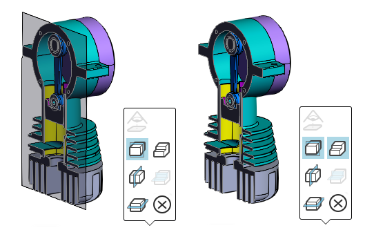
The middle icon in the right column toggles whether the cutting planes are in the same cutting section or different cutting sections. By default, each cutting plane will be created in a new cutting section. Clicking the icon will move them all to the same cutting section and turn the background color light blue. Clicking it again will move the cutting planes into separate sections.
The bottom icon on the right clears all cutting planes from all cutting sections. If there are no active cutting sections, the clear icon will be disabled.