User Guide
Translating Interactively from within 3DEXPERIENCE
The 3DEXPERIENCE CATIA V6 to CREO translator allows an opened 3DEXPERIENCE CATIA V6 part or Assembly to be exported directly to CREO, and for a CREO part or assembly to be imported directly into the 3DEXPERIENCE CATIA V6 application.
In order to translate from within 3DEXPERIENCE CATIA V6, the 3DEXPERIENCE CATIA V6 application must be started using a Theorem environment, so that the appropriate Theorem partner plug-ins are available. (See 3DEXPERIENCE CATIA V6 Environment files)
3DEXPERIENCE CATIA V6 can be started from a desktop shortcut created at installation time.
Alternatively, it can be started via the script provided in the Translator installation located in: <installation_directory>bin
The script name is:
start_3DEXPERIENCE_Theorem_Multi-CAD_CREOxx_CATIAV6R<version>
(where xx should be substituted with the version of CREO 4, 6 or 7, and <version> should be substituted for the version of 3DEXPERIENCE CATIA V6 that you have installed - e.g. 2017x, 2018x, 2019x, etc.):
Theorem Interactive Conversion Settings
The 3DEXPERIENCE interface offer a number of setting to enable configuration of the Translation Process.
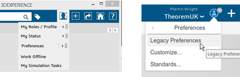
These are accessed through the User Preferences options (Preferences/Legacy Preferences for 2019x onwards) :-
Of importance for all versions is the Compatibility options page as shown below:-
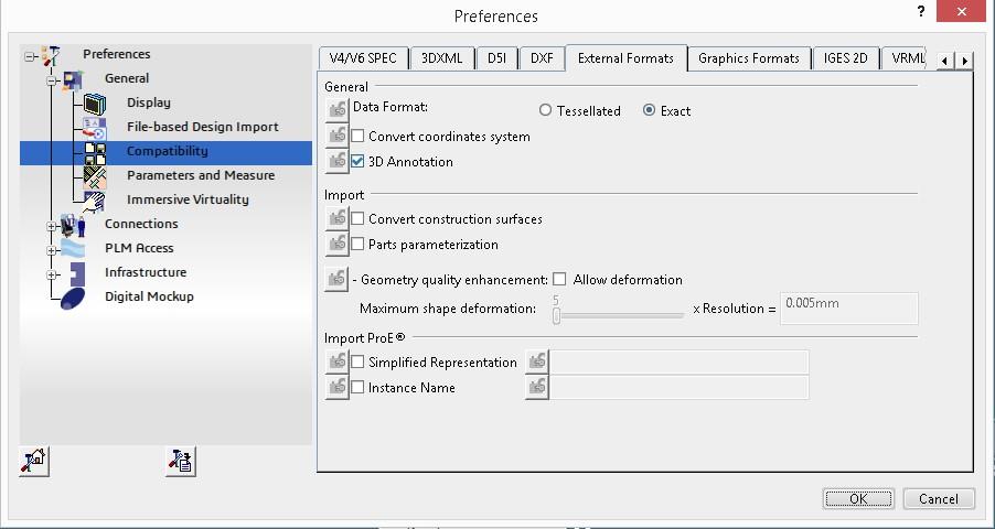
This page sets the preferred mode of conversion (in this case Exact), and also the general options “Convert coordinate systems” and “3D Annotation”.
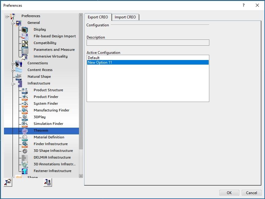
A dedicated page of options for ‘Infrastructure -> Theorem ‘ Export and Import CREO’ operations is available under the ‘Infrastructure’ settings and is presented as follows:-
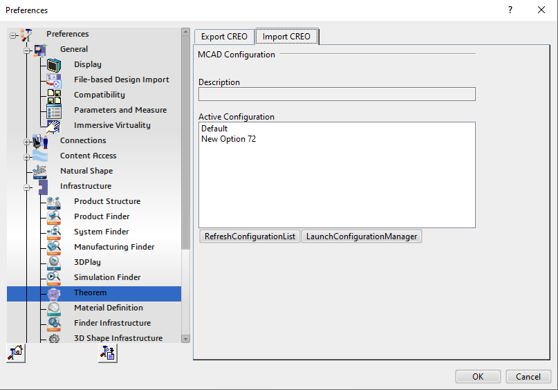
From this Panel, the user can select a predefined configuration, these are set from within the UI (see section UI) or Configuration Manager. You can also launch and refresh the Configuration Manager.
Theorem Export
Once 3DEXPERIENCE CATIA V6 has been started it is possible for an opened product to be exported to CREO. The user selects the menu item as shown here:-
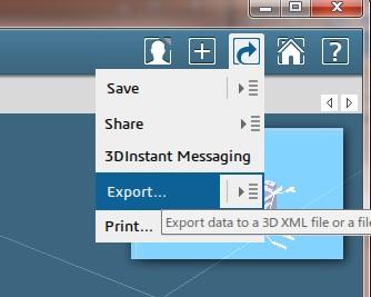
This menu action will then present the user with a Save As dialog box similar to this:-
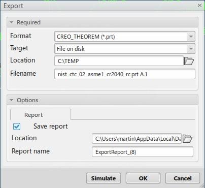
The “Save as types:” or “Format” selection should be set to CREO_THEOREM (*.prt or *.asm).
The Save or OK button can now be pressed to initiate the conversion to the selected output file name and location.
Theorem Import
Once 3DEXPERIENCE CATIA V6 has been started it is possible for a model to be imported from NX.
In order to import, the user selects the following Menu Option:
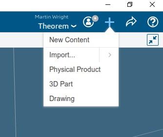
This launches the Theorem Import Menu:
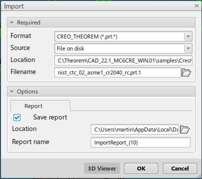
On selecting Open or OK the on the File selection Panel the NX data will be translated and imported into the 3DEXPERIENCE CATIA V6 database. It will also be opened in the user’s session.
Translating from the UI (User Interface)
For CATIA V6 there are no physical files on disk. So to run a User Interface process a job file is used instead of CAD files. This job file contains all the necessary information to locate, open and translate the V6 data. Running a translation with a job file is similar to running CADverter with file based CAD models e.g. for CATIA V5. More about the job file and its contents is described in the Job Files section below.
CADverter allows the information that is read from the source system and written to the target system to be tailored via a set of user specified arguments. Commonly used arguments are supported via the Unified Interface, with Advanced Arguments being described within this document for use in the Unified Interface or via the Command Line invocation.
Configuration Manager
The configuration Manager can be run from either the Unified Interface or by running “<theorem_install>/bin/ConfigurationManager.cmd”. Select CADverter Translator required, select the New option to create a new configuration file and then select the options required. The config file will then be available from the <Preferences><Infrastructure><Theorem> tab.
3DExperience Read Arguments
The image below shows the 3DExperience Read arguments that are available, with their default settings:
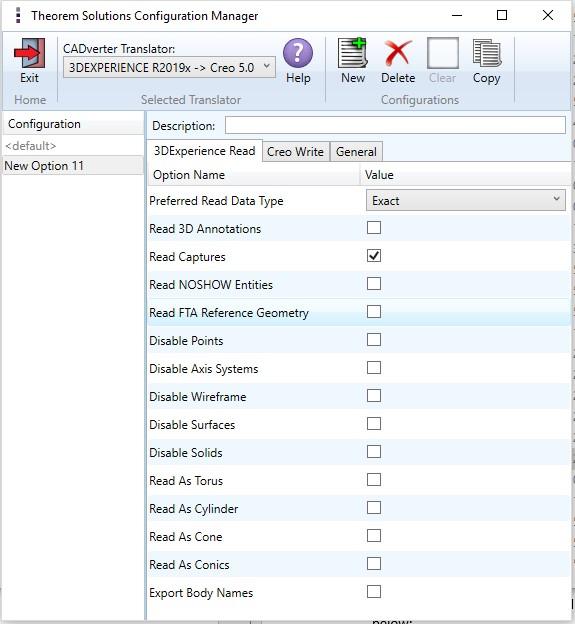
Each of these options is described below:
Option |
Description |
|---|---|
Preferred Read Data type |
Select data to be read as either Exact or Tessellated. Command Line Syntax: |
Read 3D Annotations |
Enables PMI data read from the V5 file. (Default is OFF). Command Line Syntax: Note When |
Read Captures |
A secondary argument to ‘Read PMI’ and allows the control over whether captures are read as part of the process. Default is ON when ‘Read PMI’ is marked as ON. Command Line Syntax: |
Read NOSHOW entities |
Read any entities that are in NOSHOW. Default is to not read NOSHOW entities. Command Line Syntax: |
Read FTA Reference Geometry |
Enables reading of FTA Reference Geometry (Default is Off). Command Line Syntax: |
Disable Points |
Switches off Point processing. Command Line Syntax: |
Disable Axis Systems |
Switches off Axis System processing. Command Line Syntax: |
Disable Wireframe |
Switches off Wireframe processing. Command Line Syntax: |
Disable Surfaces |
Switches off Surface processing. Command Line Syntax: |
Disable Solids |
Switches off Solids processing. Command Line Syntax: |
Read as Torus |
Read Toroidal surfaces in analytical form (default is NURBS). Command Line Syntax: |
Read as Cylinder |
Read Cylindrical surfaces in analytical form (default is NURBS). Command Line Syntax: |
Read as Cone |
Read Cone surfaces in analytical form (default is NURBS). Command Line Syntax: |
Read as Conic |
Read surfaces generated from a Conic in analytical form (default is NURBS). Command Line Syntax: |
Export Body Names |
Maintains body names for parts that consist of multiple bodies. Command Line Syntax: |
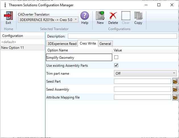
CREO Write Arguments
Option |
Description |
|---|---|
Simplify Geometry |
Attempt to write Analytical Geometry where possible (Default is Off). Command Line Syntax: |
Use existing Assembly Parts |
If Output Folder already contains output Files of the same name, do not Overwrite those Files (Default is Off). Command Line Syntax: |
Trim part name |
If the part name is over 30 characters, use the first X characters and the final (X-30) characters to reach the 30 character limit. |
Seed Part |
Use a Creo Seed Part file when creating the Creo output. Command Line Syntax: |
Seed Assembly |
Use a Creo Seed Assembly file when creating the Creo output. Command Line Syntax: |
Attribute Mapping File |
Select a standard property mapping file. Command Line Syntax: |
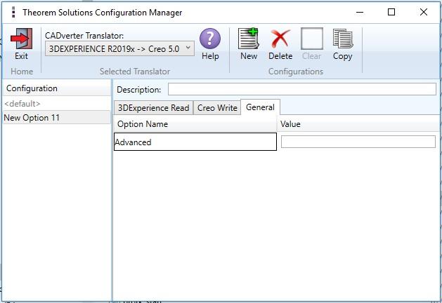
Advanced options
Any of the advanced arguments can be added to the Command Line Invocation or to the General->Advanced field when run from within the User Interface.
Option |
Description |
|---|---|
edge to nurbs |
Convert curves to NURBS. Default is OFF. |
surf to nurbs |
Convert surfaces to NURBS. Default is OFF. |
no_check_geom |
Disable solid geometry checking during CREO read operations. Possibly improve throughput by allowing the write of geometry which may not pass the geometry checks. |
no_datum_curve |
Disable the processing of Datum Curves. |
disable_default_colours |
Disable applying default colours to un-coloured entities. |
process_hidden_geom |
Process all geometry, including hidden layers. |
read_pmi |
Process PMI data. |
read_assy_pmi |
Process PMI found at the assembly level. |
write_stroked_pmi |
Causes PMI information to be stored in stroked(rendered) form as required by MultiCAD. |
CREO Read Arguments
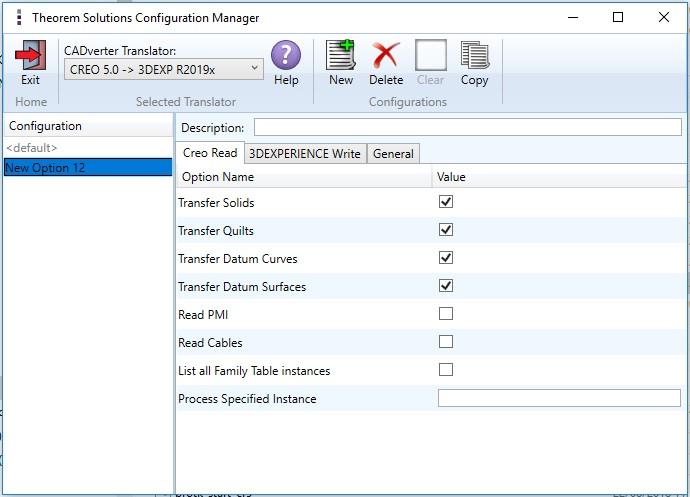
Each of these options is described below.
Option |
Description |
|---|---|
Transfer Solids |
Enables solid processing. (Default is on). Command Line Syntax: |
Transfer Quilts |
Enables quilt processing. (Default is on). Command Line Syntax: |
Transfer Datum Curves |
Enables Datum Curve processing. (Default is on). Command Line Syntax: |
Transfer Datum Surfaces |
Enables Datum Surface processing. (Default is on). Command Line Syntax: |
Read PMI |
Enables PMI data processing. (Default is off). Command Line Syntax: |
Read Cables |
Enables the reading of Cable data from Creo. (Default is off). Note that in
the Creo Configuration Editor, the setting Command Line Syntax: |
List all Family Table instances |
List all instances of Family table to the progress file. (Not to be used in conjunction with Process Specified Instance). (Default is off). Command Line Syntax: |
Process Specified Instance |
Process Specified Instance (Not to be used in conjunction with ‘List all Family Table instances’). Command Line Syntax: |
3DExperience Write Arguments
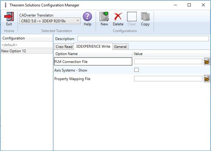
Option |
Description |
|---|---|
PLM Connection File |
The PLM Connection file is one of the xml files defining the connection parameters to the PLM database. It is required to create a connection and logging into a PLM session programmatically. |
Axis Systems - Show |
Show all translated Axis Systems. |
Property Mapping File |
Assign a property mapping file. Command Line Syntax: |
Translating in Batch using CATUtil - PLMBatchDataExchange
The Dassault Systemes CATUTIL batch management tool can be launched with the correct Theorem enabled environment using the scripts provided in the Translator installation at:
<installation_directory>\bin\start_CATUTIL_Theorem_Multi-CAD_CREO_CATIAV6R<revision>.cmd
(where [revision] should be substituted for the version of 3DEXPERIENCE that you have installed - e.g. 2013x, 2014x, 2015x, 2016x)
The settings made in the user options page “MultiCAD CREO” described in the interactive usage above, are also used in BATCH mode.
In some cases, it may be desirable to ignore the interactive settings while running in batch mode.
This can be achieved by setting the following variable in the CATIA Environment being used:
TS_IGNORE_CREO_CATSETTINGS=1
Batch Export to CREO
Here is an example showing the appropriate settings in preparation for a database selection and an export “save” or “run”:-
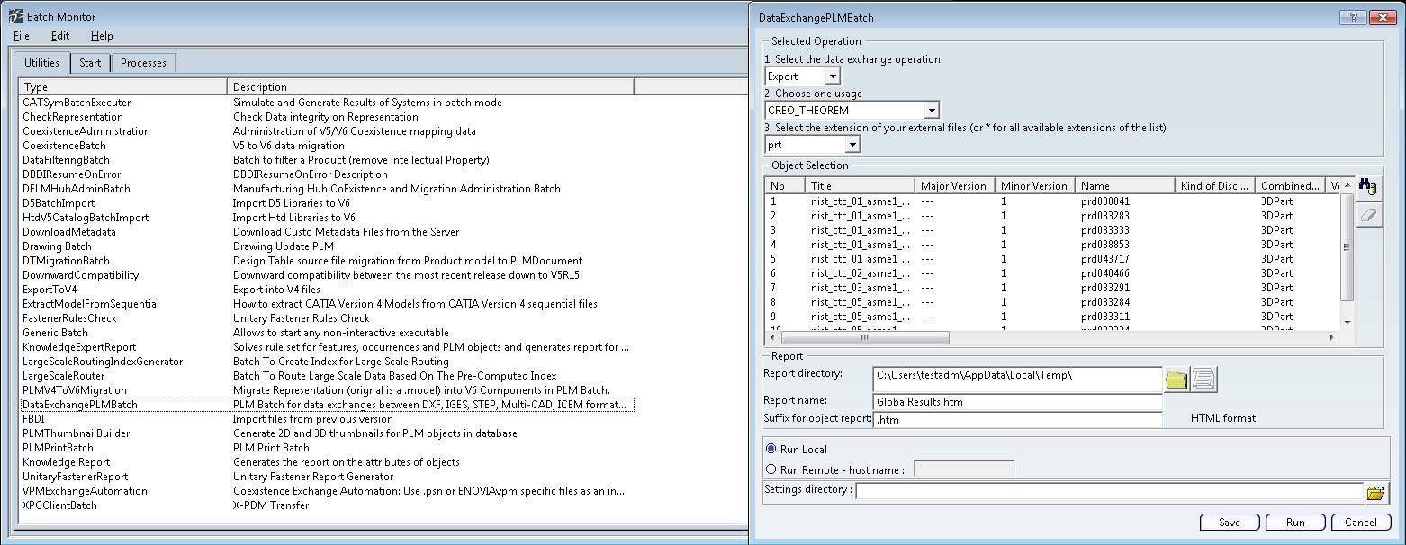
Note selection of “Export” operation, usage “CREO_THEOREM” and extension “prt”.
Batch Import from CREO
Here is an example showing the appropriate settings in preparation for an input CREO file selection and an export “save” or “run”:-
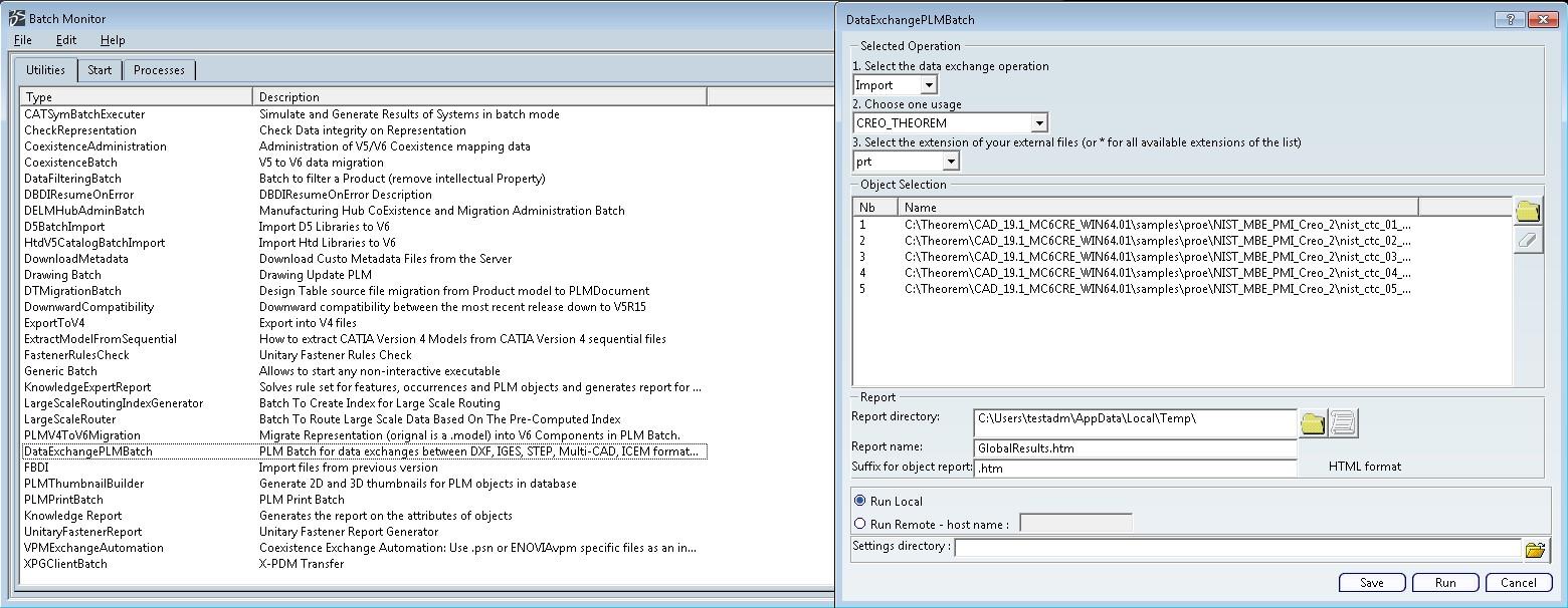
Note selection of “Import” operation, usage “CREO_THEOREM” and extension “prt”.
Export process Log Files
In the process of exporting the selected 3DEXPERIENCE CATIA V6 part or assembly, the following log files are generated by the CREO Export plug-in.
The process log and error messages are recorded in a ‘.err’ file located in the 3DEXPERIENCE CATIA V6 CATReport directory. The file is named after the active CATIA component.
e.g. %CATReport%model1.err
Additional log files are created in the TSC_TEMP_DIR directory. This directory is defined in the %TS_INST%ts_env.bat file.
%TSC_TEMP_DIR%Read_to_viewer_<input_part_name>.log
Where: <input_part_name> is the name of the input part (or the active part name in interactive usage) This contains information describing the 3DEXPERIENCE CATIA V6 ‘data read’ processing into Theorem Intermediate data format
%TSC_TEMP_DIR%viewer_<part-name>_screen_output.log
Where <part-name> is the selected output file name This contains the screen output of the process of writing the data to CREO.
%TSC_TEMP_DIR%viewer_<part-name>.log
Where <part-name> is the selected output file name This contains detailed process information of the write of the data to CREO.
Import process Log Files
In the process of importing a CREO file, the following log files are generated by the CREO Import plug-in.
The process log and error messages are recorded in a ‘.err’ file located in the 3DEXPERIENCE CATIA V6 CATReport directory. The file is named after the selected input file name. e.g. if the file Mypart.prt were selected, the log file names would be %CATReport%Mypart.err and %CATReport%Mypart.rpt.
%TS_TEMP_DIR%<input_file_name>_viewer.log
%TS_TEMP_DIR%<input_file_name>_viewer_screen_output.log
%CATReport%<input_file_name>.err
Where <Input_file_name> - is the base file name of the imported file.
3DEXPERIENCE CATIA V6 Environment Files
As part of the Theorem installation process, a set of 3DEXPERIENCE CATIA V6 environment files are created which are subsequently used in the launch of 3DEXPERIENCE and CATUtil sessions to support the Theorem partner plug-ins for CREO import and export.
A ‘CATEnv’ file is created for each installed version of 3DEXPERIENCE CATIA V6.
These environment files are located in
<install_dir>B420win_b64CATenvTheorem_Multi-CAD_CREOx_CATIAV6R2018x.txt
<install_dir>B421win_b64CATenvTheorem_Multi-CAD_CREOx_CATIAV6R2019x.txt
<install_dir>B422win_b64CATenvTheorem_Multi-CAD_CREOx_CATIAV6R2020x.txt
<install_dir>B423win_b64CATenvTheorem_Multi-CAD_CREOx_CATIAV6R2021x.txt
Where x = Version of CREO installed
Job Files
Batch Processing
As part of the development of Large Assembly Processing, a new batch processing utility has been created for 3DEXPERIENCE V6 CATIA export to Creo View. This runs as a command line executable which requires the following inputs:-
<TS_INST>bincatia6R2017X_pdf.cmd <input_file> <output_path <output_file>
Where:- <TS_INST> is the Theorem Solutions software installation directory.
<input_file> is an xml file defining the access to a specific object in a specified 3DEXPERIENCE PLM database.
This file provides user login details (V6R2019x) or a Login Ticket (2019x), to a specified Enovia repository plus a set of 3 attribute names and values which will uniquely identify the input PLM object of the conversion.
Here is an example of the xml input file for 3DEXPERIENCE V6 R2019x:-
<?xml version="1.0" encoding="utf-8"?>
<mc6_read>
<!-- parameters must be in this ORDER -->
<!-- parameters only the value passed to V6  -->
  <parameters>
    <attribute name="repository" value="PLM1"/>
    <attribute name="ServerName" value="3dspace.2019x.theorem.com"/>
    <attribute name="ServerPort" value="447"/>
    <attribute name="ServerRootURI" value="3dspace"/>
    <attribute name="LoginTicket"
    value="QzdBRTA4NzEzN0I5NDRFNTlFRTUOM0RFMDRFRDc1N0N8Um9iaW4xNnh8
    Um9iaW4xNnh8fHwwfA=="/>
    <attribute name="PLMType" value="VPMReference"/>
    <attribute name="ReportDirectory" value="C:\TEMP\V6Export"/>
    <attribute name="LicenseData" value="LIC"/>
    <attribute name="BatchXMLFileName" value="Default"/>
  </parameters>


  <!-- arguments both key and value are passed to V6 -->
  <arguments>
    <attribute key="PLM_ExternalID" value="sprd-49550079-00000063"/>
    <attribute key="V_version" value="A"/>
    <attribute key="minorrevision" value="1"/>
  </arguments>
</mc6_read>
Creating a Login Ticket
Use a browser link (similar to the one below) to your 3DExperience Server https://3dspace.2019x.theorem.com:447/3dspace/common/emxNavigator.jsp
A page will appear in the browser
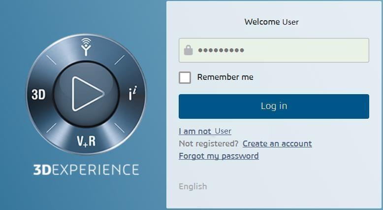
Login as normal, e.g.
User
Password
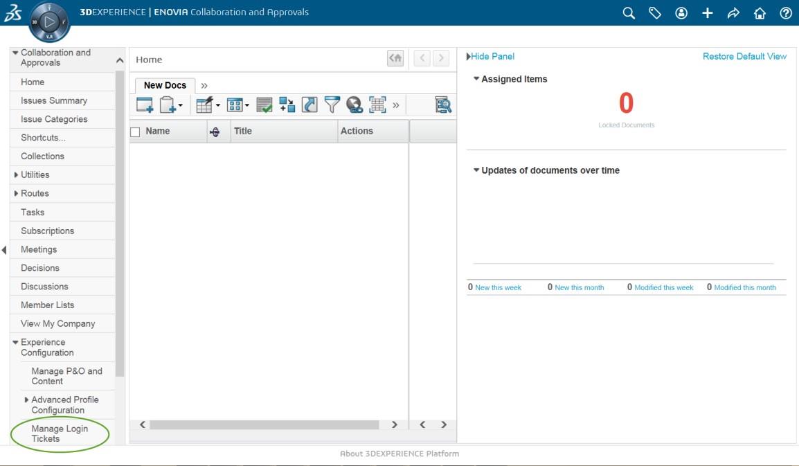
Select Collaboration and Approvals > Experience Configuration > Manage Login Tickets
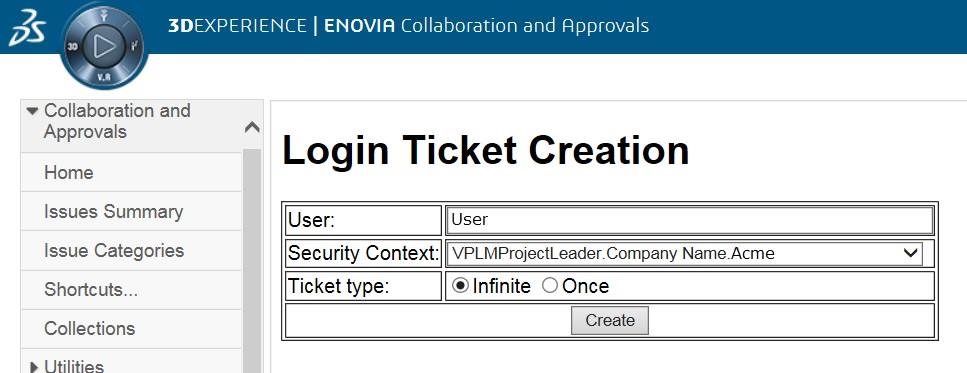
Select the values required for your user:
User and Security Context should already be set, make sure that Ticket Type: Infinite is selected. Then click on ‘Create’
“Create” will produce the ticket:-
REEyNzM3STE1MER2NDgxQzlFNzk1QzIwNjZGNATzDAN8Um9iaW58Um9iaW58fHwwfA==
This can then be used as the ‘LoginTicket’ value in the job xml file described in Job Files section above.