User Guide
Using the Product
Default Translations
Default Translation – via the Unified Interface
The Unified Interface can be started via the Start Menu – if a shortcut was added during installation.
Alternatively, the Unified Interface can be run via a Windows Explorer selection in:
<UI_installation_directory>\bin\Unified_Interface.cmd
The following interface will be launched:
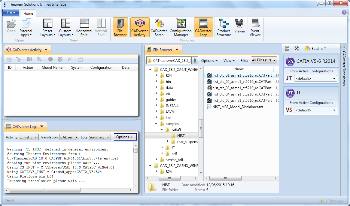
The default layout is split into 4 primary areas, which can be altered to the users prefer:
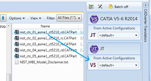
The simplest way to translate from CATIA V5 or JT is to drag a file from the file Browser Pane on to the Active Configurations for the translation you require.
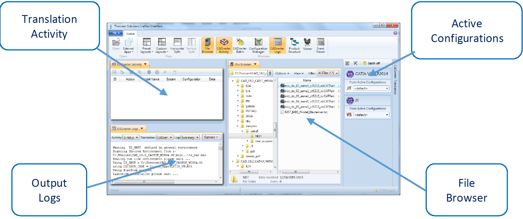
On completion, the Unified Interface will display the activity information and details from the log file created during the translation, if requested, in the Translation Activity and Output Log panes, respectively.
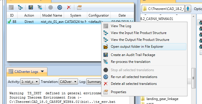
The generated output data can be located by selecting the translation from the Activity pane and opening the output folder:
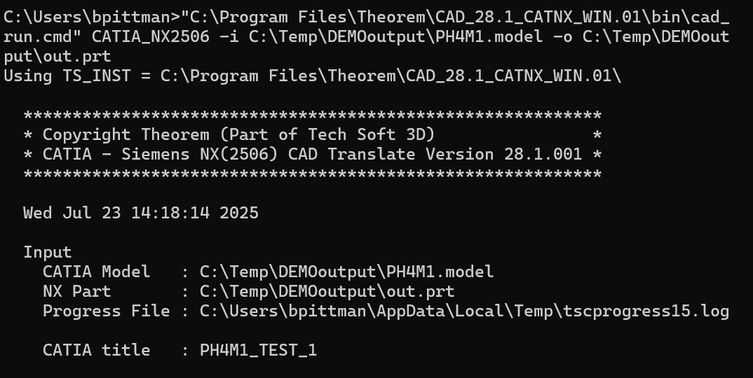
Default Translation – via the Command Line
Running a translation via the command line can be carried out via the cad_run.cmd file located in the
<installation_directory>\bin directory. The format of the command is as follows when translating from CATIA
V4 to NX:
<Translator_installation_directory>\bin\cad_run.cmd CATIA_NX[XX] <input_file> <output_file>
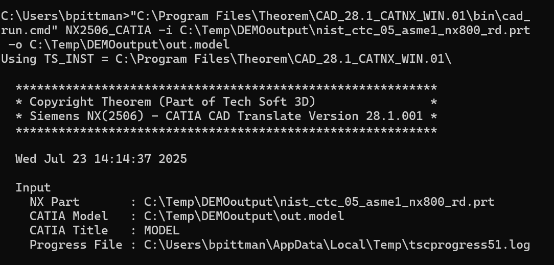
The format of the command is as follows when translating from NX to CATIA V4:
<Translator_installation_directory>\bin\cad_run.cmd NX[XX]_CATIA <input_file> <output_file>
(Note! Replace the [XX] seen in the example with the version of CATIA V4 you are using. E.g. for CATIA V4)
Customizing Translation Output
The following sections describe, in outline, available command line arguments to customize the output of the CATIA V4 to NX translator.
Some of these arguments are available via the Unified Interface. All can be used as additional arguments on the default command line:
CATIA V4 to NX Arguments List
CATIA Read Arguments List
CMD LINE Option |
Purpose |
Data Type |
Default |
|---|---|---|---|
|
Model number in export file |
Int |
1 |
|
Mainframe real conversion |
Flag |
Off |
|
Read Entity Tag Names |
Flag |
Off |
|
Read Entity Tag Names |
Flag |
Off |
|
Unknown |
Flag |
Off |
|
Continuity required |
Tolerance |
Off |
|
Primitive surface redefinition required |
Flag |
Off |
|
Explode assembly structure during read |
Flag |
Off |
|
Colour visualization mode as per set, layer, entity type or view |
Choice set layer etype view |
Off |
|
Dimensions are view realm |
Flag |
Off |
|
Dimensions are draft realm |
Flag |
On |
|
Read associated set name and store in attribute |
Flag |
Off |
|
Heal partially degenerate surfaces |
Flag |
Off |
|
Displays information panel in progress file |
Flag |
On |
|
Read entities in named sets |
Char * |
All |
|
Read named entities |
Char * |
All |
|
Creates a surf check file |
Char * |
|
|
Catia graphism font mapping file |
Char * |
|
|
Search path used to file model files whilst reading asm or session files |
Char * |
|
|
only_use_search_path |
Flag |
Off |
|
Read colours as applied to solid faces |
Flag |
Off |
|
Read colour applied to solid |
Flag |
On |
|
Process pdegen surfs |
Flag / Tol |
Off |
|
Group pipes in a detail |
Flag |
Off |
|
Group pipelines in a detail |
Flag |
Off |
|
Dont group pipelines in a detail |
Flag |
Off |
|
Names axis as per associated text |
Flag |
Off |
|
Names axis as per tag name i.e. *AXS1 |
Flag |
On |
|
Specify layer on which to put pipe line |
Int 1-254 |
Use pipe segment layer |
|
Read facet colours for solidm |
Flag |
Off |
|
Dont read facet colours for solidm |
Flag |
On |
|
Read validation properties |
Flag |
Off |
|
Calculate validation properties on individual volumns |
Flag |
Off |
|
Calculate absolute validation properties |
||
|
Calculate validation properties if hidden |
||
|
validation properties report file name |
Char * |
|
|
validation properties output file name |
Char * |
|
|
Read noshowed entities |
Flag |
Off |
|
Read 2D draftings enitities |
Flag |
Off |
NX Write Arguments
CMD LINE Option |
Purpose |
Data Type |
Default |
|---|---|---|---|
|
For gco Fsolids produce Facetted bodies (else attempt brep) |
Flag |
off |
|
attempt a UG heal on the created body (if nocheck on) |
Flag |
off |
|
If input solid gets created as a solid after sewing, plus one or more tiny sheet bodies, keep or delete these |
Flag |
on (keep all) |
|
Don’t check created Parasolid geometric entities |
Flag |
off |
|
Prepare solids switched off |
Flag |
on (surfs read as nurbs+prep) |
|
Enable Parasolid tolerant modeling |
Flag |
on |
|
Sew failed breps and opensols |
Flag |
on |
|
Prepare CSG Prinitives |
Flag |
off |
|
Change CSG Shift Distance |
Flag |
off |
|
Fix CSG Primitives |
Flag |
off |
|
Remove small edges, sliver and spike faces in breps |
Flag |
off |
|
Remove small edges, sliver and spike faces in opensolids |
Flag |
off |
NX to CATIA V4 Arguments List
NX Read Arguments List
CMD LINE Option |
Purpose |
Data Type |
Default |
|---|---|---|---|
|
Read UG entity names (if they exist) |
Flag |
off |
|
Process As Saved part layers, else All |
Flag |
ALL |
|
Read PMI as stroked data |
Flag |
off |
|
Prepare solids switched off / on |
Flag |
on (surfs read as nurbs+prep) |
|
Read native edge curves |
Flag |
off (read as nurbs curves) |
|
Trim surface to face |
Flag |
off (don’t trim) |
|
Switch on validate read to progress file |
Flag |
off |
|
Switch on read diagnostics to progress file |
Flag |
off |
|
No Parasolid merging of entities |
Flag |
on (merge) |
|
Check Parasolid entities before read |
Flag |
off (don’t check) |
|
Read Mass Props |
Flag |
off |
|
Process 2D drawings |
Flag |
off |
CATIA Write Arguments List
CMD LINE Option |
Purpose |
Data Type |
Default |
|---|---|---|---|
|
Create a mainframe real conversion model file |
Flag |
Off |
|
Produce a Catia V3 file |
Flag |
Off |
|
Controls surface optimization tolerance |
Double |
Off / 0.001 |
|
Maximum solid faceting tolerance to be applied to solids which are found to be too large to go into CATIA |
Double |
Off |
|
Catia Model Dimension. Followed by number, followed by blank or “inch” or “mm” specfies model dimension to be number of part units, inch or mm. |
Double |
Off |
|
Name of model to be used as seed part to provide site specific information to the created CATIA model file |
Char * |
Off |
|
Prefix of Startpart file to use allows automatic switching dependent on units |
Char * |
Filename |
|
Create import solides rather than volumes |
Flag |
Off |
|
Create complex volume solide rather than volume (doubles size of model file) |
Flag |
Off |
|
Creates faceted solidm |
Flag |
Off |
|
By default we create a model file version 4.1.5 this allows version to be set higher |
Char * |
Off |
|
Override default colour map |
Flag |
Off |
|
Use default entity colours |
Flag |
Off |
|
Use default ditto colours |
Flag |
Off |
|
Create standalone curve and surface entities in NURBS form |
Flag |
Off |
|
Create 3D edge curves for faces on volumes |
Flag |
Off |
|
Simplifies BREP to tolerance may also define the tolerance |
Flag / Double |
Off / 0.01 |
|
Display volume ids as default |
Flag |
Off |
|
Switch display of skin ids off by default |
Flag |
On |
|
Display face ids as default |
Flag |
Off |
|
Set colour on BREP faces |
Flag |
Off |
|
Set colour on BREP solid |
Flag |
On |
|
Create session file by creating an IUA procedure |
Flag |
Off |
|
Create export file |
Flag |
Off |
|
Defines file to use as export header |
Char * |
|
|
Display standalone plane ids as default |
Flag |
Off |
|
Display standalone plane boundary |
Choice OFF, SOLID, DOTTED, DASHED, DOT-DASH |
Off |
|
Display surface boundary |
Choice OFF, SOLID, DOTTED, DASHED, DOT-DASH |
Off |
|
Allow surface boundary pick |
Flag |
Off |
|
Display surface lines |
Choice OFF, SOLID, DOTTED, DASHED, DOT-DASH |
Off |
|
Disallow surface iso-parametric line pick |
Flag |
Off |
|
Number of surface iso-parametric lines in U |
Int (0-99) |
1 |
|
Number of surface iso-parametric lines in V |
Int (0-99) |
1 |
|
Display face boundary |
Choice OFF, SOLID, DOTTED, DASHED, DOT-DASH |
Solid |
|
Allow face boundary pick |
Flag |
Off |
|
Display face lines |
Choice OFF, SOLID, DOTTED, DASHED, DOT-DASH |
Off |
|
Disallow face line pick |
Flag |
Off |
|
Number of face lines in U |
Int (0-99) |
1 |
|
Number of face lines in V |
Int (0-99) |
1 |
|
Display point ids |
Flag |
Off |
|
Display 3D point symbol |
Choice DOT, PLUS, CROSS, STAR |
DOT |
|
Display 3D line font |
Choice SOLID, DOTTED, DASHED, DOT-DASH, PHANTOM |
Solid |
|
Display 3D curve font |
Choice SOLID, DOTTED, DASHED, DOT-DASH, PHANTOM |
Solid |
|
3D Wireframe default thickness |
Int 1-60 |
2 |
|
Display 2D point symbol |
Choice DOT, PLUS, CROSS, STAR |
DOT |
|
Display 2D line font |
Choice SOLID, DOTTED, DASHED, DOT-DASH, PHANTOM, BREAK |
Solid |
|
Display 2D curve font |
Choice SOLID, DOTTED, DASHED, DOT-DASH, PHANTOM, BREAK |
Solid |
|
2D Wireframe default thickness |
Int 1-60 |
2 |
|
Defined file for mapping of catia graphisms to site specific intereger |
Char * |
Off |
|
Create a skin for an opensolid > 1 face |
Flag |
On |
|
Dont create a skin for an opensolid > 1 face |
Flag |
Off |
|
Hide surfaces subordinate to a face |
Flag |
On |
|
Dont hide surfaces subordinate to a face |
Flag |
Off |
|
Switches current face respect of view visualization mode (i.e. Shades) |
Flag |
Off |
|
Switches current volume respect of view visualization mode (i.e. Shades) |
Flag |
On |
|
Switches current skin respect of view visualization mode (i.e. Shades) |
Flag |
On |
|
Switches current standalone surface respect of view visualization mode (i.e. Shades) |
Flag |
Off |
|
Dont convert 2x2 NURBS surface surporting a face to a plane |
Flag |
Off |
|
Display volume internal edges |
Choice OFF, SOLID, DOTTED, DASHED, DOT-DASH |
Solid |
|
Make volume edges unpickable |
Flag |
Off |
|
Display volume lines |
Choice SOLID, DOTTED, DASHED, DOT-DASH |
Solid |
|
Make volume lines pickable |
Flag |
Off |
|
Number of volume lines in U |
Int (0-99) |
1 |
|
Number of volume lines in V |
Int (0-99) |
1 |
|
Display skin boundary edges |
Choice OFF, SOLID, DOTTED, DASHED, DOT-DASH |
Solid |
|
Make skin boundary pickable |
Flag |
Off |
|
Display skin internal edges |
Choice OFF, SOLID, DOTTED, DASHED, DOT-DASH |
Solid |
|
Make skin internal edge pickable |
Flag |
Off |
|
Display skin lines |
Choice SOLID, DOTTED, DASHED, DOT-DASH |
Solid |
|
Make skin lines unpickable |
Flag |
Off |
|
Number of skin lines in U |
Int (0-99) |
1 |
|
Number of skin lines in V |
Int (0-99) |
1 |
|
Create a CADDS PS structure file pointing at CATIA V4 model files |
Char * |
Off |
|
If session file or CADDS PS file dont create empty CATIA model files |
Flag |
Off |
|
If session file or CADDS PS file, process leaf nodes |
Flag |
|
|
Convert PCURVES to ARCS with tolerance |
Double |
Off / 0.00001 |
|
Set the identical curve tolerance to <tol> |
Double |
Off |
|
UNKNOWN |
||
|
Trim supporting face surfaces to face boundary |
Flag |
On |
|
Trim supporting face surfaces to face boundary |
Flag |
Off |
|
Split BREP |
Flag |
Off |
|
Check skin / solid can sew to tolerance |
Double |
Off / mdim |
|
Name entity from tag as opposed to *FACXX form |
Flag |
Off |
|
Name entity using *FACXX form |
Flag |
On |
|
Redefine face edges for surfaces which original patch boundary may contain C1 discontinuity |
Flag |
On |
|
Use original face edge definition for surfaces which original patch boundary may contain C1 discontinuity |
Flag |
Off |
|
Dont change routed items to BREP definition |
Flag |
Off |
|
Dont include inner radius in changing routed items to BREP definition |
Flag |
Off |
|
Change routed items to BREP definition |
Flag |
On |
|
Dont write conic solid edge curves as conies |
Flag |
Off |
|
Create conics edge centers on layer specified else layer 254 |
Flag / Int |
Off / 254 |
|
Produce a validation properties file which can be checked using a API program |
Flag |
Off |
|
Dont change individual facet colours |
Flag |
Off |
|
Produce dimensions and multiline texts as draw symbols |
Flag |
Off |
|
Produce simple texts as draw symbols |
Flag |
Off |
|
Move all draw entities to layer specified (default 9) |
Flag / Int |
Off / 9 |
|
Process view dependent edits on 3D lines |
Flag |
Off |
|
Process view dependent edits on 2D & 3D lines |
Flag |
Off |
|
Produces CADS NFIGS as draw symbols |
Flag |
Off |
|
Produce text with 0 360 writing rule |
Flag |
Off |
|
Produce text with -90 +90 writing rule |
Flag |
On |
|
Produce text with geo writing rule |
Flag |
Off |
|
|||
|
Enables followings options draw_nfigs, draw_wr_geo, draw_2d_lines, draw_layer, draw_symbols, override_colour, draft. catia_fonts <catia_font_file> |
Flag |
Off |
|
Allows a file to be defined similar to a mask file which allows entities to be created in NOSHOW |
Char * |
Off |