User Guide
Introduction
Overview
The CATIA V5i CADverter allows the user to translate CATIA V5 assemblies (.CATProduct files), components (.CATPart) from their original CATIA V5 format into the PTC Creo View .pvs, .ed and .ol file formats. The CADverter is developed using Spatial Independent CGM Interface and therefore is independent of the CATIA V5 application.
Support for specific CATIA V5I Release
CATIA V5I Object CADverters are available for support of the following releases of the CATIA V5 Application including all Service Packs at the nominated release.
CATIA V5 revisions R25 up to CATIA V56R2021(R31)
Using the Product
Via the Unified Interface
The Unified Interface can be started via the Start Menu – if a shortcut was added during installation.
Alternatively, the Unified Interface can be run via a Windows Explorer selection in:
<UI_installation_directory>binUnified_Interface.cmd
The following interface will be launched:
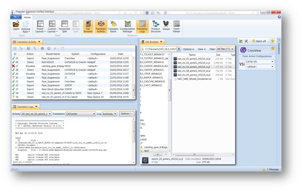
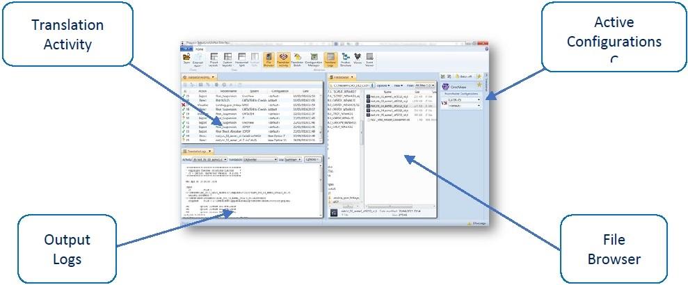
The default layout is split into 4 primary areas, which can be altered to the users prefer:
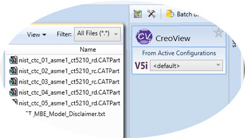
The simplest way to translate from CATIA V5i to Creo View is to drag a file from the file Browser Pane on to the Active Configurations for the translation you require.
On completion, the Unified Interface will display the activity information and details from the log file created during the translation, if requested, in the Translation Activity and Output Log panes, respectively.
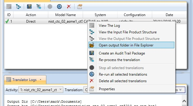
The generated output data can be located by selecting the translation from the Activity pane and opening the output folder:
Translation Configuration
It is recommended that the CATIA V5I to Creo View CADverter be run from a pre-created configuration. Theorem have adopted the standard PTC Configuration tools which will create a batch script for running the CADverter on the command line and also a worker script to allow the CADverter to be run with WindChill.
For full details of this process, please see our ‘How to Configure the CATIA V5I to Creo View via CADverter’ demonstration video located here.
To take full advantage of the configuration tools and to configure the CADverter as an adapter for use as a Windchill Worker please contact your PTC representative to provide the Windchill Installation and Configuration Guide Catia5_CreoView.
Default Translation
Default Translation – via the Command Line
Running a translation via the command line can be carried out without using a pre-created configuration. This will use the default translator settings. This is achieved by directly running the script file located in the <installation_directory>bin directory. The format of the command is as follows:
<Translator_installation_directory>\bin\catia5i_pv.cmd <input_files> -p <output_path> -o <output_file>

The example above will translate a sample file provided within the installation and produce the following screen output:
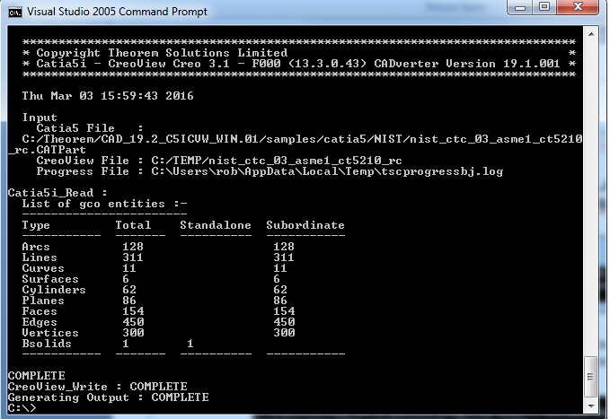
The file will be output to the target location. In this case:
C:\TEMP\nist_ctc_03_asme1_ct5210_rc
The above example provides the minimum command line arguments required to create an output. In order to support the PTC Windchill interface, Theorem have also adopted the PTC Adapter command line syntax, a full list of available options is shown below and can be displayed by issuing the following command:
<Translator_installation_directory>\bin\catia5i_pv.cmd -h
Setting |
Result |
|---|---|
<@File> |
Read Options from the response file <file> |
-?-h |
For basic help page. UNIX may try to export the “?” so –h should be typed in quotes, for example, “h”. |
-d <depth> |
Set the conversion file depth. When converting an assembly file determines to what depth the hierarchy should be traversed. The default is all. |
-H |
For extended help options |
-o<name> |
Set output file base name (number of input files must be 1). |
-p<name> |
Set output base path. |
-r<name> |
Set recipe to <name> |
-vc |
Disable all console print-out. |
-vc1 |
Redirect all console print-out to stdout. |
-vc2 |
Redirect all console print-out to stderr (default) |
-ve[n] |
Increment or set (if[n]is given) the error reporting level. –ve0 disables all error reporting, default 1. |
-vl<file> |
Direct all printed output to <file> |
-vL<file> |
Concatenates all printed output to <file> |
-vn<file> |
Direct all printed output to new log file <file>-#.log. |
-vp<n> |
Set the process verbosity flag. List the modules by –I. Flags are listed in the source code. |
-vw[n] |
Increment or set the warning reporting level, see -vc |
-vt |
Give the current date/time stamp with all print outs. |
-j<name> |
Get job from <name> .paj file |
-epdconnect |
Enable EPD.Connect orientated conversion. |
-mockup |
Enable MockUp oriented conversion process |
Translator Customization
In the case of the Creo View Translators, they are all configured using a recipe file, consequently the UI allows the user to point to the required recipe file for the translation settings.
Common Options for CATIA V5i to Creo View
Within the Configuration Manager pane of the Unified Interface, arguments that can be specified when publishing CATIA V5 data into Creo View are grouped into the following areas.
CreoView Recipe selection – Those arguments that affect how data is read from CATIA V5. The setting up of this recipe file to achieve the desired results is explained later in this document:
CATIA V5i Read Arguments
The image below shows the CATIA V5I Read arguments that are available, with their default settings:

Each of these options is described below:
Option |
Description |
|---|---|
Use recipe file |
Use a specific recipe file to create the required results Command Line Syntax:
|
Configuring the Recipe File for the CATIA V5I Object Adapter
Configuring the CATIA V5I Creo View CADverter using the Recipe Editor
For completeness this section of the User Guide describes the available configuration options provided by the recipe editor.
A recipe is a set of user-defined rules that drive the individual CAD Adapter. The recipe concept provides a solution to the problem of efficiently converting CAD data into a form suitable for viewing on a wide range of computer platforms. Like its analogy in cooking, gaining a desired result requires cooking to a specific recipe. While most CAD parts will convert into an efficient form for large-scale visualization, some parts require modifications to the standard visualization recipe to be viewed effectively.
The CATIA V5i Adapter is provided with a master or default recipe file. This file is pre-configured to allow the visualization of most objects. The master recipe file should not be edited. Instead, additional new recipes can be created from this default file using Save As function in the recipe editor (rcpedit) provided with the translator.
For full details concerning the Recipe Editor, please refer to the ‘Creo View MCAD Adapters Installation and Configuration Guide’ document, which can be obtained via the PTC Reference Documents Site.
Theorem’s Creo View CADverters use the standard PTC mechanism to Configure translation option. The basic concepts and available options are covered here for convenience.
Theorem provide a configuration script to allow a recipe file to be created. Running the following script will launch the Recipe Editor Configuration Tool:
<Translator_installation_directory>bincatia5i_pv_config.cmd
The panel below will be displayed:
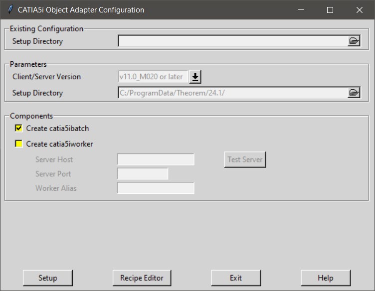
The Configuration Tool allows the CATIA V5i Creo View CADverter to be configured for use in batch (via the command line) and/or for use in a Windchill environment (catia5worker). Please contact your PTC representative to provide the Windchill Installation and Configuration Guide Catia5i_CreoView for full details on configuring in a Windchill environment. This guide will focus on running the translator from the command line, but all of the configuration options are available in both environments.
The ‘Create catia5ibatch’ selection will create a recipe file for batch and the ‘Create catia5worker’ will create a recipe file for a Windchill invocation. Having selected either of these options (and provided a valid Windchill Host and Port) the ‘Setup’ button will become active. Selection of the ‘Setup’ button will launch the following panel:
This can be accepted and the ‘Recipe Editor’ button will become active.
The ‘Setup’ action will create a new directory beneath the translator installation directory. So, the user that creates new configurations will need write access to the translator installation directory. The first configuration directory will be named catia5i_setup. Subsequent configurations will will named catia5i_setup’n’ (where ‘n’ is a unique number). In this manner many different configurations can be created. The configuration directory will contain an invocation script that will deliver a default Configuration that uses default translation settings. Selection of the ‘Recipe Editor’ button will allow the user to set specific translation settings.
The contents of a Configuration folder are:
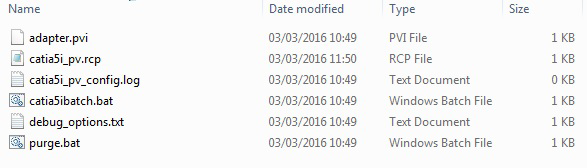
The catia5ibatch.bat script will be used in preference to the Theorem provided script discussed in the Default Translation – via the Command Line section and will use configuration options specified in the catia5i_pv.rcp (recipe) file.
Running a translation using the catia5ibatch.bat script can be achieved using the following command
<Translator_installation_directory>\catia5i_setup\catia5ibatch.bat <input_files> -p <output_path> -o <output_file>
The results and screen output will be the same as that noted for the Default Translation.
Configuring the Recipe File for the CATIA V5I Object Adapter
A recipe is a set of user-defined rules that drive the individual CAD translation tools. The recipe concept provides a solution to the problem of efficiently converting CAD data into a form suitable for viewing on a wide range of computer platforms. Like its analogy in cooking, gaining a desired result requires cooking to a specific recipe. While most CAD parts will convert into an efficient form for large-scale visualization, some parts require modifications to the standard visualization recipe to be viewed effectively.
The CATIA V5I Object Adapter is provided with a master or default recipe file. This file is pre- configured to allow the visualization of most objects. You should not edit the master recipe. Additional new recipes can be created from this default file using Save As function in the recipe editor (rcpedit).
The Using the Recipe Editor document describes the steps you should take to create a new recipe file for your particular configuration. Using the Recipe Editor explains the recipe concept and describes the settings available for each object adapter. A copy of the document “Using the Recipe Editor with CAD Object Adapters” can be obtained by contacting your local PTC customer support department.
Customizing Your Object Adapter Output
After installing, configuring, and testing you object adapter, you may decide that you want to further customize the output. You can customize your object adapter output by using the recipe editor. Using the Recipe Editor describes a number of specific customizations users will be interested in configuring. The list provided next is not meant to be exhaustive, but includes the following specific recipe configuration instructions:
Changing what information is published by an object adapter.
Optimizing for viewing on Windows or UNIX platforms.
Changing the accuracy of the visual representation.
Fixing any conversion issue such as holes or cracks.
Enabling or disabling CATIA V5I layer states.
The information available in Using the Recipe Editor is periodically updated. For the latest information, download the document from the PTC web-site noted above.
Using The Recipe Editor To Configure Options
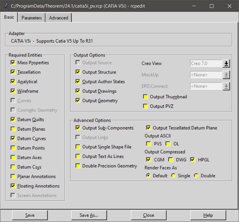
The recipe editor has an advanced options tab, which contains a number of sub menus which allow the user to control the Theorem translation settings. To access these options :
Launch the recipe editor:
rcpedit.exe <recipe file name>
The recipe editor GUI will be displayed as follows (example):
Specifying a Recipe file on the command line
For any option set in a recipe file, once the recipe file has been saved, the translator can take advantage of the settings by referring to the recipe file on the command line:
e.g. catia5i_pv.cmd <input file> -r <recipe file name>
Theorem Recipe V5I Options
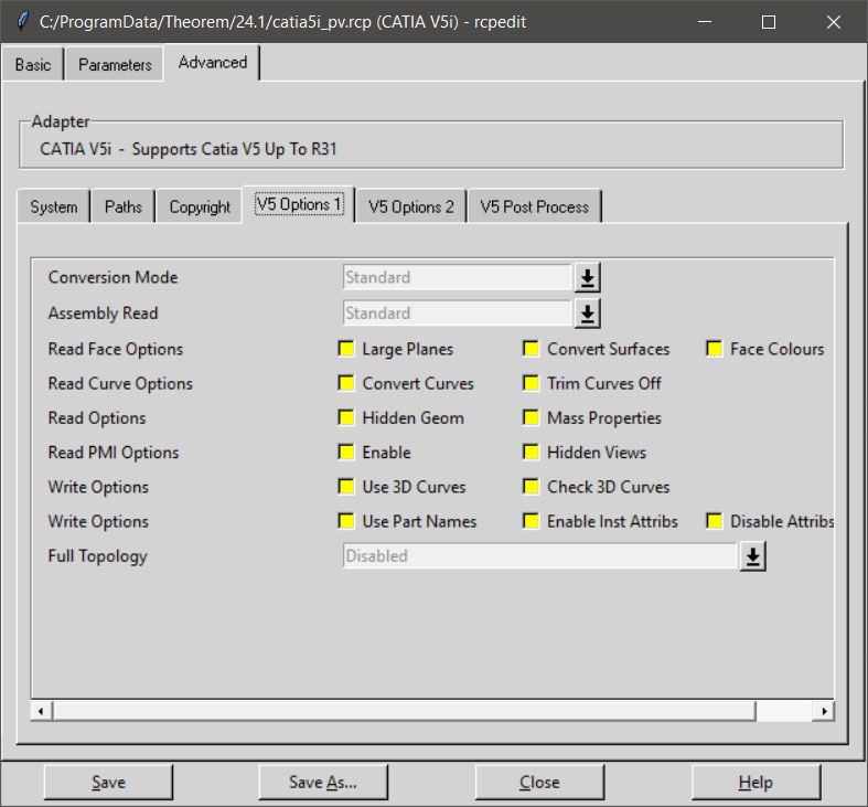
Select the V5I Options Tabs :
Options 1 contains the main functions.
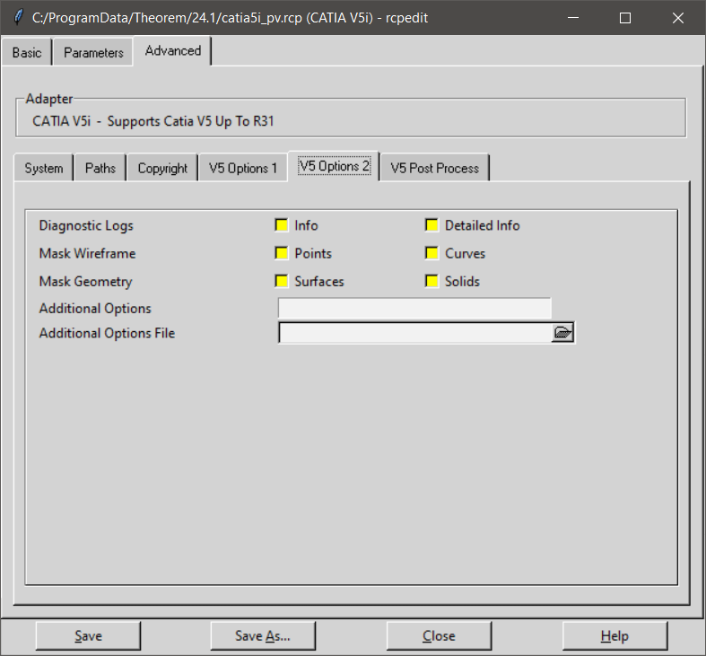
Options 2 allows masking and additional options
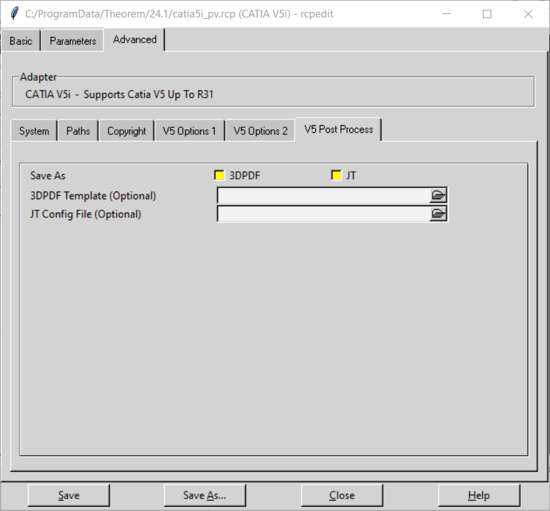
Theorem Recipe V5I Post Process
Post Process allows conversion of the same data to 3D PDF or JT if you have purchased the additional add-on packages.
A description of these commands are shown below
Option |
Description |
|---|---|
Conversion Mode |
The user has the option to process Assembly information in one of 2 modes:
Standard: The default method for assembly processing reads a CATIA V5I assembly and its entire geometry contents into memory, before writing out all of the data to Creo View. Minimum Memory: A more efficient way of processing the data has been provided via the Minimum Memory conversion mode selection. This mechanism reads in the assembly data then process each “.CATPart” file referenced by the assembly on a part by part basis. See the section on Large Assembly Processing Best Practises for more info. |
Assembly Read |
The user 3 option to process Assembly information :
Standard - uses a direct read of the Catia5 data Lite - Structure Only - Uses a lite weight read designed to read large assemblies quickly, this setting will just read the assembly structure. Lite - Structure & Geom - Uses a lite weight read designed to read large assemblies quickly, followed by minimum memory processing for the parts. |
Large Planes |
Allows the user to omit large PLANEs where the bounding exceeds 0.1Km in any direction. These faces are most often construction planes. The bounding box size can be adjusted by using the additional argument set_omit_large_planes <value in M>, see additional options for details. |
Hidden Geom |
Allow selective data types to be read regardless of hide/show state. Default is OFF. Command Line Syntax:
|
Hidden Views |
Reads any Views that are hidden |
Convert Curves |
Convert curves to NURBS. Default is OFF. Command Line Syntax:
|
Convert Surfaces |
Process data (read) types as NURBS. Data type is selected from options. Default is Fillets. Command Line Syntax:
|
Trim Curves Off |
Trims face surfaces. Default is ON. Command Line Syntax:
|
Enable (Read PMI) |
Read CATIA V5I PMI, such as annotations, GDT and Dimensions. |
Use 3D Curve |
This option allows Creo View API to generate its own 2D curves. This option is most likely only ever used as a work-around when poor data is encountered. |
Check 3D Curves |
This option allows the CADverter to test the data and if necessary automatically enable Use 3D Curves. A default tolerance of 0.01 (1%) face/surface overlap being used for these checks. This tolerance can be adjusted with validate_3D_curve_tol <value> in the additional option field. |
Use Part Names |
Use the CATIA V5I ‘part number’ names for assembly nodes. The default is to use ‘Instance name’. |
Instance Attributes |
Enables the output of any instance attributes. |
info |
Add information messages to the progress file |
Detailed info |
Add detailed information (diagnostics) messages to the progress file |
Full Topology |
Controls how the topology is written into Creo View data. By default this is ‘disabled’, which is consistent with earlier releases of the product. The default setting generates good viewable data, but since each face of a solid is written separately it is not possible to calculate mass properties such as volume, correctly view capping sections or perform 3D Compare or Interference Detection in the Creo View client. Options are: Disabled
Enabled
Enabling full topology can increase translation times, so we suggest that the user selects the minimum setting that required. For example, don’t use the Fix non-manifold settings unless necessary and don’t use the Quilts setting unless required. |
Additional Options |
Not ALL options for to the CATIA V5i Creo View CADverter are made available to the recipe editor. These options are not in common use, but can be included here should they ever be required, please delimiting each option with a space ” ” character. Some example of additional options are detailed in a separate section : |
Additional Options File |
Any of the Additional Options can be specified in an Additional Options File, known as a ‘Theorem Configuration File’. Use this option to specify a configuration file to use. |
Theorem Recipe V5I Filter Options
Select the V5I Filter Options Tab :
Mask Off |
Description |
|---|---|
Face Colours |
Disable the processing of face colours. |
Attributes |
Disable the reading of attributes |
Points |
Disable the reading of points |
Solids |
Disable the reading of solids |
surfaces |
Disable the reading of free surfaces |
Wireframe |
Disable the reading of wirefrane |
Theorem Recipe V5I Post Process Options
Select the V5I Post Process Tab :
Save as |
Description |
|---|---|
Save As PDF |
Output PDF file as well as Creo View Data |
Save As JT |
Output JT file as well as Creo View Data |
3D PDF Template |
Define a non default template (XML) file used to control the options and publish style in writing the PDF file. |
JT Config File |
Define a non default config file (tess.config) used to control the options in writing the JT file. |
Save As JT & PDF Files
When these options are selected, the V5I data is read, with a common set of options and then written with write options defined in the related JT configure file or PDF template file.
The default JT configuration file is found in :
%TS_INST%etctessCATIA5ISaveAs.config
The recipe editor allows any JT configuration file to be used, if the default is not suitable.
The default PDF template file is found in :
%TS_INST%datapublish_3dpdfdefaultManifest.xml
Which in itself references :
%TS_INST%datapublish_3dpdfpublish3d_options.txt
Which defines the PDF write leg options
The recipe editor allows any PDF template to be selected.
Save As Option Licenses
NOTE: Additional license(s) are required to use save as JT and PDF
CATIA V5i to CREOVIEW Advanced Arguments
Theorem’s CATIA V5i to CREOVIEW translator has been configured with default settings that optimises the translation process. However, there are times when a satisfactory result cannot be obtained, so it may be required to deploy one or more Advanced Arguments to improve the translated result. (Using the Additional Options field in the recipe editor)
Option |
Description |
|---|---|
Conversion Tolerance |
A secondary argument to ‘Convert Curves’ defining the conversion tolerance. Default is 0.00001 Command Line Syntax:
|
Conversion Tolerance (Surfaces) |
A secondary option to ‘Convert Surfaces to NURBS’. Defines the conversion tolerance. Default is 0.00001. Command Line Syntax:
|
UDF Axis Systems |
Enable reading of User Defined Axis systems. Default is OFF. Command Line Syntax:
|
Filter Geometry |
It is possible to filter large planes (construction planes) larger than a given size using (default being 1000 meters) Command Line Syntax:
There is a special case for PLANES (typically construction planes) which by default are not read, these can be enabled using Command Line Syntax:
|
Categorise PMI |
PMI is categorised by type. Default is ON. Only selectable if ‘Read PMI’ is selected. This can be switched off using Command Line Syntax:
|
single_jt_file_in_pvoa |
If this option is selected ONLY the top level JT file is added to a .pvoa file when a job file (.paj) is processed, otherwise all subordinate part JT files are store in the .pvoa file - so that a whole assembly is stored in the .pvoa file. |
attr_filter_file <filter file> |
A default Attribute Filter file is supplied in: %TS_INST%/data/creoView/defaultAttrFilter.txt The default locations can be overridden by specifying a value to the attr_filter_file command. Filtering can be disabled by specifying a non-existing file with ‘attr_filter_file’ OR deleting the defaultAttrFilter.txt The essential settings for an attr_filter_file are: Attribute Name; New Attribute Name; Mode Where:
|
set_omit_large_planes <value> |
Omit large PLANEs greater than the tolerance value (default is 100 M) e.g. set_omit_large_planes 2000 - sets a value of 2km |
disable_opacity |
Disable the writing of opacity settings into Creo View data |
pmi_RGB <rrr-ggg-bbb> |
Set a default colour for PMI text and graphics, this will override the colours read from CATIA V5. The argument rrr-ggg-bbb, MUST be given as 3 values 000 to 255 for each of the colours with a ‘-’ char between, for example: pmi_RGB 000-000-000 – for black text pmi_RGB 255-255-255 – for white text |
Mass Properties |
CATIA V5I mass properties (volume/area CofG) are read and any applied materials, using this option, in cases where a part has multiple solids, volume and area values are summed, but CofG data is invalid. Command Line Syntax:
|
Assembly Processing
Processing CATIA V5I Assemblies (.CATProduct files)
Assuming that the input to the CADverter was a single assembly named test_assembly.CATProduct related to many subordinate parts (.CATPart) files then the output from the translator will be a single Creo View assembly file test_assembly.pvs plus many geometry .ol files, one for each part file processed.
Given that the example assembly file had additional assembly files subordinate to it then all of the accumulated assembly hierarchy information would be output into the top level Creo View .pvs file.
The CATIA V5I Creo View CADverter takes advantage of the latest Creo View dAPI which writes .pvs files ( Creo View binary assembly structure files) by default. If a user wishes to write out earlier .pvs versions or .ol files, this can be achieved via the appropriate setting the recipe editor.
Processing CATIA V5I Parts (.CATPart files)
For each part (.CATPart) file processed individually then the output from the translator will be a single Creo View assembly .pvs file and a single geometry .ol file. Therefore assuming that the file being processed was named test_component.CATPart then the output would be test_component.pvs and test_component.ol
Efficient Large Assembly Processing
If an assembly is opened using the CATIA V5I application or API (CAA), all subordinate assembly and all related geometry will be loaded into memory. This is very inefficient in terms of memory usage.
Theorem have made improvements to assembly read efficiency in the following areas:
Each .ol file is now written and all associated memory freed on a file by file basis, such that in writing to Creo View there is no build up of memory.
Although the translation process is constrained by the CATIA V5I API reading all assembly and geometry information into memory, it is now possible to write out each geometry and assembly file on a file by file basis. This functionality can be invoked by either selecting the the “minimum memory” conversion mode option.
The combination of the 2 efficiency improvements detailed here provides in excess of a 20% memory saving on larger (>50MB) assemblies. In general the larger the input assembly the greater the saving will be.
Large Assembly Processing Best Practices
Processing large CATIA V5I assemblies often requires access to large amounts of resources. This can be a combination of both available disk space as well as memory resources. As described above, the default method that the CATIA V5I API uses to consume assembly data compounds this issue. Therefore the following steps are advised as best practices for working with large assemblies:
Use the Minimum Memory Mode recipe setting described in section “Running In Minimum Memory Mode”
For further assistance with this setting, please refer to your CATIA V5I on-line help.
Minimum Memory Mode for Very Large Assemblies
Additional Large Assembly read options are provided that may provide some benefits, particularly in Windchill implementations that deploy Positioning Assemblies.
These options should only be considered for use having liaised with your PTC Windchill support team.
Error Tracking and Management
A method of tracking and managing errors output from the CATIA V5I to Creo View process has been provided. This is implemented by setting exit status codes from the CADverter and additionally the creation of a summary file for each translation task. The structure of the summary file enables detailed analysis of the translation task to be verified.
CADverter Exit Status Codes
The software will return one of the following exit status codes:
These codes will be returned regardless of the type of data being processed, either single parts or assemblies. If the error code returned is 1 (e.g. Completed with errors) the user will be directed to look at a summary file that details the exact reason for failure.
Summary File Definition
Each translation creates a summary file using the standard name “tscsummarybj” located in the temporary directory. The user can override the default name using the environment variable TSC_SUMMARY_FILE.
The name of the active summary file is recorded in the progress file:
WINDOWS default name=%TEMP%tscsummary
Output is recorded in the summary file with a single line reporting a status for each item processed. Each line is defined using 4 fields, separated by a “,” character. Each field represents the following data:
e.g. C:mypartssample.CATPart,0,Completed with no errors,/usr/data/sample.CATPart.log
When processing either single parts or assemblies using the default recipe file settings, only one line will appear in the summary file. However for assemblies processed using the minimum memory mode methodology or with links enabled the summary file will contain a line for each “.CATPart” and “.CATProduct” file translated.
Summary File Error Codes
The following Error Codes are output the Summary File:
Worker Logs
The Adapter writes key messages to the PTC worker logs, these include the summary error codes (positive values are used in these logs, e.g. 3 = input file not found).
The Theorem messages added to the worker logs are always prefixed by ‘TS:’, for clarity, and are written at two levels of detail 0x01 and 0x10. These messages are enabled via the –vm command line with the correct bit mask level for logs required.
e.g.
–vm 1 will enable all 0x01 messages
-vm 11 will enable all 0x01 AND 0x10 messages.
The –vL <log file> command line can be used to re-direct these messages to a file.
In the event of an error the summary code will be written to the worker log he positive value of the summary code :
e.g.
8 => No entities found.
Process Timeouts
Timeouts allow a user to control when an individual translation invoked from a WindChill environment should timeout.
The WindChill interface allows 2 distinct timeout types to be defined, Long and Short.
Three simple timeouts have been allocated to the CATIA V5->Creo View translator, one using the Short Timeout value and two using the Long Timeout value setting:
Long Timeout – Catia5i_Read, to read each file from CATIA V5.
Long Timeout – CreoView_Write, to write each file into Creo View
The Timeout values can be set as follows:
Launch the recipe editor: rcpedit.exe <recipe file name>
Select the Adapter Tab
Having selected CATIA V5I from the adapter pull-down, followed by the System Tab, the recipe editor GUI will be displayed as follows:
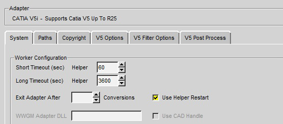
Apply an appropriate time for the Short and Long timeout (in seconds).
Note! These times are totally dependent upon the user data. Some trial and error may be required to define the best times for a specific user environment.
It is recommended that timeouts should NOT be used when running the software with its default settings. They should only be deployed when running translations in minimum memory mode or with links enabled. This will allow the LONG timeout setting to be reduced, as using these options will instruct the translator to process assemblies one part at a time.
Theorem Support Advanced Options
Introduction
The following environment variables are available to modify the CADverters behaviour under the guidance of the Theorem support team.
It is recommended, under guidance from Theorem Support that these variables be set in the ts_env.bat file, if required.
Where no value is suggested, set the variable with a value of 1:
e.g.
set TSC_DEBUG=1
Diagnostics
Variable |
Value |
Description |
|---|---|---|
TSC_DEBUG |
1 |
Annotate logs and screen output with debug data. Note! Much of the TSC_DEBUG info is now re-directed via the –vm <level> command line option into the worker log |
TS_V5I_CVW_KEEP_VWR_FILE |
1 |
Retain any intermediate GCO files |
Testing
Variable |
Value |
Description |
|---|---|---|
TS_TEST_WORKER_MODE |
1 |
Simulate worker mode |
TS_TEST_POSITIONAL_ASSY |
1 |
Simulate Positional Assembly Mode In WindChill |
TS_POSITIONAL_ASSY_DEPTH |
1..n |
Set a depth for Positional Assembly default is 1 |
3D PDF Publish
Variable |
Value |
Description |
|---|---|---|
TS_V5_CV_SAVE_3DPDF_PUBLISH_MODE_OFF |
1 |
Disable 3D PDF publish mode, create 3D PDF file without publish template |