User Guide
Using the Product
Default Translations
Default Translation – via the Unified Interface
The Unified Interface can be started via the Start Menu – if a shortcut was added during installation.
Alternatively, the Unified Interface can be run via a Windows Explorer selection in:
<UI_installation_directory>\bin\Unified_Interface.cmd
The following interface will be launched:
The default layout is split into 4 primary areas, which can be altered to the users preference:
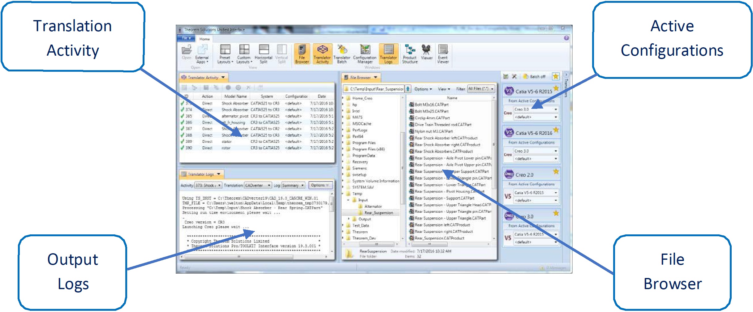
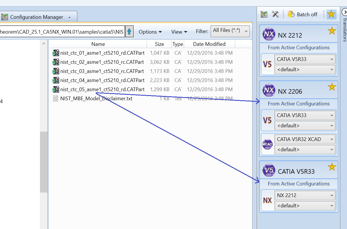
The simplest way to translate from CATIA V5 or NX is to drag a file from the file Browser Pane on to the Active Configurations for the translation you require.
On completion, the Unified Interface will display the activity information and details from the log file created during the translation, if requested, in the Translation Activity and Output Log panes, respectively.
The generated output data can be located by selecting the translation from the Activity pane and opening the output folder.
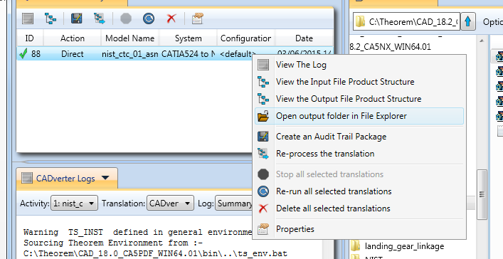
Default Translation – via the Command Line
Running a translation via the command line can be carried out via the cad_run.cmd file located in
the <installation_directory>\bin directory. The format of the command is as follows when
translating from CATIA V5 to NX:
<Translator_installation_directory>\bin\cad_run.cmd CATIA5[XX]_NX[XX] -I <input_file> -o <output_file>
The format of the command is as follows when translating from NX to CATIA V5:
<Translator_installation_directory>\bin\cad_run.cmd NX[XX]_CATIA5[XX] -I <input_file> -o <output_file>
(Note! Replace the [XX] seen in the example with the version of CATIA V5 or NX you are using. E.g. for CATIA V5 R33, change to CATIA533 and for NX 2212 change to NX2212):

The example above will translate a CATIA V5 sample file provided within the installation and produce the following screen output.
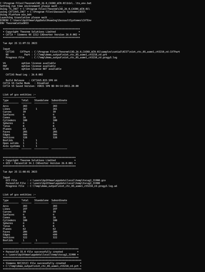
The file will be output to the target location. In this case:
C:\Temp\nist_ctc_05_asme1_ct5210_rd.prt
Translator Customization
The Theorem translator allows the information that is read from the source system and written to the target system to be tailored via a set of user specified arguments. Commonly used arguments are supported via the Unified Interface, with Advanced Arguments being described within this document for use in the Unified Interface or via the Command Line invocation.
Common Options for CATIA V5 to NX
Within the Configuration Manager pane of the Unified Interface, arguments that can be specified when publishing CATIA V5 data into NX are grouped into 4 areas:
CATIA V5 Read – Those arguments that affect how data is read from CATIA V5
NX Write – Those arguments that affect how the data is written to NX
Entity Mask – Those arguments that allow specific read entities to be masked
General – Those arguments that are common to ALL Publishing activities regardless of source data
CATIA V5 Read Arguments
The image below shows the CATIA V5 Read arguments that are available, with their default settings:
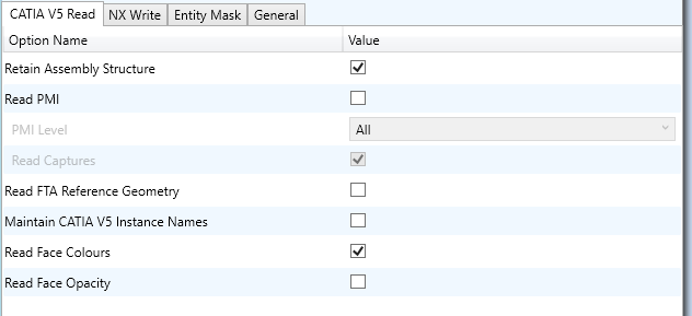
Each of these options is described below:
Option |
Description |
|---|---|
Retain Assembly Structure |
Enables Assembly Structure to be retained (Default is On). Disabling this option will remove all assembly structure and collapse ALL geometry into a single selectable object. Command Line Syntax:
|
Read PMI |
Enables PMI data read from the V5 file. (Default is ON). Command Line Syntax:
Note – When |
PMI Level |
A secondary argument to ‘Read PMI’ and allows control of the level of PMI to be read. Default is ALL when ‘Read PMI’ is marked as ON. Options Available (command line syntax in italics and square brackets next to the option):
|
Read Captures |
A secondary argument to ‘Read PMI’ and allows the control over whether captures are read as part of the process. Default is ON when ‘Read PMI’ is marked as ON. Command Line Syntax:
|
Read FTA Reference Geometry |
Enables reading of FTA Reference Geometry (Default is Off). Command Line Syntax:
|
Maintain CATIA V5 Instance Names |
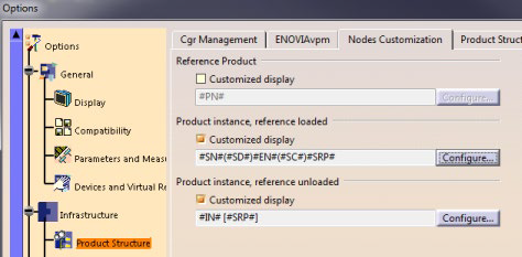
Honours CATIA V5 Tools->Options->Infrastructure->Product Structure->Nodes Customization panel settings (Default is Off). Command Line Syntax:
|
Read Face Colours |
Processing geometry colours by face. Command Line Syntax:
|
Read Face Opacity |
Processing face opacity. Command Line Syntax:
|
NX Write Arguments
The image below shows the Write NX arguments that are available, with their default settings:
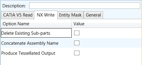
Each of these options is described below:
Option |
Description |
|---|---|
Delete Existing Sub-parts |
Delete existing sub-parts. Default is OFF. Command Line Syntax:
|
Concatenate Assembly Name |
Concatenates assembly name. Default is OFF. Command Line Syntax:
|
Produce Tessellated Output |
Produce Tessellated NX file. Default is OFF. Command Line Syntax:
|
CATIA V5 to NX Entity Masking Arguments
The image below shows the Masking arguments that are available, with their default settings:
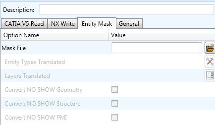
Each of these options is described below:
Option |
Description |
|---|---|
Mask File |
Specifies the Mask File to be written to, that can be referenced by future translations. A Mask file MUST be specified if masking is required. The first line in this file is OFF ALL ENT. Command Line Syntax:
|
Entity Types Translated |
Specifies a selection list from which to select which entity types are to be processed. The following types are available: “POI”,”CUR”,”SKI”,”SOL”,”ISO”,”TEX”,”AXI”. Command Line Syntax:
|
Layers Translated |
Specifies a selection list from which to select which layers are to be processed. Command Line Syntax:
|
Convert NO SHOW Geometry |
Enables Hidden geometry to be processed (Default = Off). Command Line Syntax:
|
Convert NO SHOW Structure |
Enables Hidden Assembly Structure to be processed (Default = Off). Command Line Syntax:
|
Convert NO SHOW PMI |
Enables Hidden PMI to be processed (Default = Off). Command Line Syntax:
|
CATIA V5 to NX General Arguments
The image below shows the General arguments that are available, with their default settings:
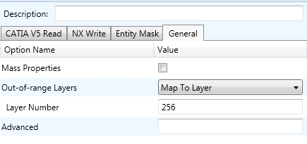
Each of these options is described below:
Option |
Description |
|---|---|
Mass Properties |
Allows Mass Property information to be read from the source data and written as attributes to the PDF document. Default is OFF. Command Line Syntax:
|
Out-of-range Layers |
How to handle layers from the input system that are out-of-range in the output system. Default is ‘Map To Layer’. Command Line Syntax:
|
Layer Number |
A secondary option used with Out-of-range Layers when ‘Map To Layer’ is selected. Allows the layer number to be specified. Default is 256. Command Line Syntax:
|
Advanced |
Allows any of the Command Line Advanced arguments documented below to be passed to the Unified Interface invocation. |
Common Options for NX to CATIA V5
Within the Configuration Manager pane of the Unified Interface, arguments that can be specified when publishing NX data into CATIA V5 are grouped into 4 areas:
NX Read – Those arguments that affect how data is read from NX
CATIA V5 Write – Those arguments that affect how the data is written to CATIA V5
Entity Mask – Those arguments that allow specific read entities to be masked
General – Those arguments that are common to ALL Publishing activities regardless of source data
NX Read Arguments
The image below shows the NX Read arguments that are available, with their default settings:
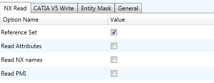
Each of these options is described below.
Option |
Description |
|---|---|
Reference Set |
Enabled reference set processing. Default is OFF. Command Line Syntax:
|
Read NX Attributes |
Read NX detail user attributes. Default is OFF. Command Line Syntax:
|
Read NX names |
Read NX entity names, if they exist. Default is OFF. Command Line Syntax:
|
Read PMI |
Read 3D PMI. Default is OFF. Command Line Syntax:
|
CATIA V5 Write Arguments
The image below shows the CATIA V5 Write arguments that are available, with their default settings:
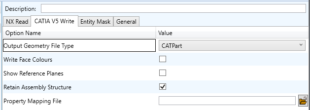
Each of these options is described below:
Option |
Description |
|---|---|
Output Geometry File Type |
Output Geometry file type. Default is CATPart. Command Line Syntax:
|
Write Face Colours |
Writes face colours. Default is ON. Command Line Syntax:
|
Show Reference Planes |
Creates reference planes. Default is OFF. Command Line Syntax:
|
Retain Assembly Structure |
Maintains the structure from the source file. Command Line Syntax:
|
Property Mapping File |
This mapping file is used to control which properties are exported from V5 to NX. Command Line Syntax:
Detail on map file structure below: Line Format: SourceName, TargetName, Control, Dummy, Dummy, Dummy Control: 0 – Do not convert, 1 – Use the source values as given By setting the control value to 0 will stop a specific property from being exported. Alternatively you can switch the property name that is found in the input data to a different name in the output file. This is performed by switching the name between the input name = field 1 and the output name = field 2. Example settings shown with “#” comment for each line: _ActivateBOM,NULL,0,,,
_LastModifier,NULL,0,,,
_Maturity,NULL,0,,,
_PrdVersion,NULL,0,,,
|
NX to CATIA V5 Entity Masking Arguments
The image below shows the Masking arguments that are available, with their default settings:
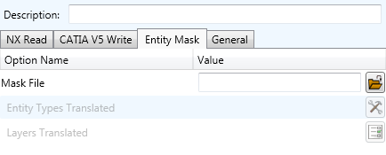
Each of these options is described below:
Option |
Description |
|---|---|
Mask File |
Specifies the Mask File to be written to, that can be referenced by future translations. A Mask file MUST be specified if masking is required. The first line in this file is OFF ALL ENT. Command Line Syntax:
|
Entity Types Translated |
Specifies a selection list from which to select which entity types are to be processed. The following types are available: “POI”,”LIN”,”ARC”,”CON”,”CUR”,”SUR”,”FAC”,”SOL”. Command Line Syntax:
|
Layers Translated |
Specifies a selection list from which to select which layers are to be processed. Command Line Syntax:
|
NX to CATIA V5 General Arguments
The image below shows the General arguments that are available, with their default settings:
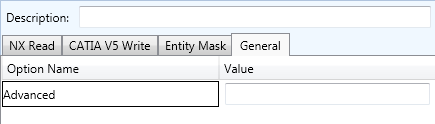
The option is described below:
Option |
Description |
|---|---|
Advanced |
Allows any of the Command Line Advanced arguments to be passed to the Unified Interface invocation. |
Command Line Advanced Arguments
Any of the Advanced arguments can be added to the Command Line Invocation or to the General->Advanced field when run from within the User Interface.
NX Advanced Arguments
Argument |
Description |
|---|---|
|
Options to support the reading of scanned data |
CATIA V5 Advanced Arguments
Argument |
Description |
|---|---|
|
Converts curves to NURBS form |
|
Converts surfaces to NURBS form |
|
Disables the read of filled arrow information (default for |
|
Disables the read of filled text information (default for |
|
Disables the read of PMI Capture information (default for |
|
Read face opacity |
|
Sets the default to SOLID colours |
Reads hidden geometry / structure / pmi |
|
|
Allows sub-part specification tree information to be read and presented to 3D PDF as
product structure information. This option also enables the |
|
CATIA V5 has a display mode that allows the display of shaded surfaces and edges. This option allows the translator to mimic this for FTA construction geometry by promoting the edge curves to standalone wireframe. |
|
Support to process NX data that contains both solid and tessellated bodies (convergent model) to CATIA V5. The solid data is created as a CATPart and the tessellated data in a CGR file then an assembly file is created to hold them together. |
CATIA V5 – NX PDF Add On Products
As an optional feature, the creation of 3D PDF documents can be added to the functionality of the CATIA V5 – NX license.
This requires an additional software download and is documented within that download. Please contact sales@theorem.com for more information.
Translating Interactively from within CATIA V5
The CATIA V5 to NX translator allows an active CATIA V5 Part or Assembly to be translated directly into NX or an NX Part or assembly to be imported, directly from the CATIA V5 application.
In order to translate from within CATIA V5, the CATIA V5 application must be started from within a Theorem environment, so that the appropriate CATIA V5 menus are loaded.
CATIA V5 can be started from a shortcut, if requested at installation time. Alternatively, it can be started via the script provided in the CADverter installation at:
<installation_directory>\bin\catia5r[version]_start.cmd
(where [version] should be substituted for the version of CATIA V5 that you have installed – e.g. 29, 30, 31, 32 & 33):
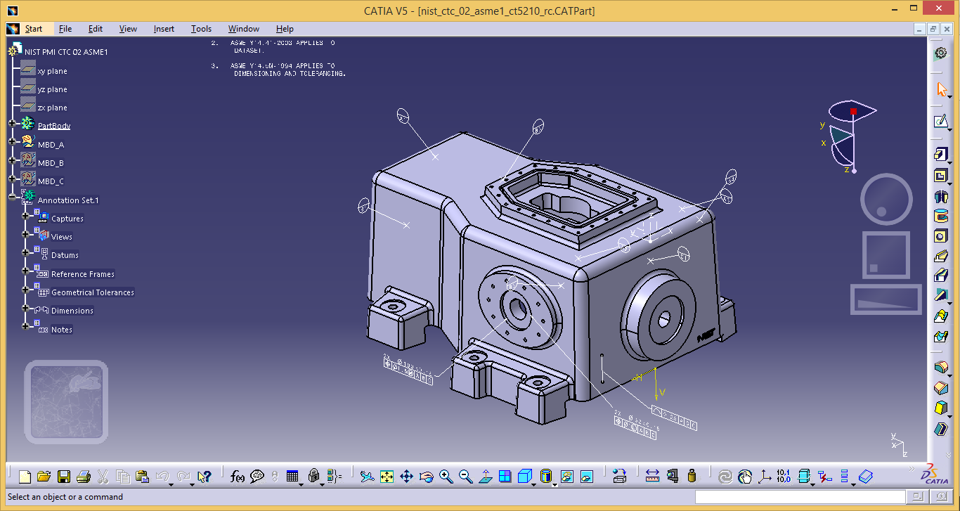
Theorem Export
Once CATIA V5 has been started and a model loaded, the active Part or Assembly can be exported to NX.
In order to export, the user selects the File -> Theorem Export Menu Option:

Which in turn launches the Theorem Export panel:
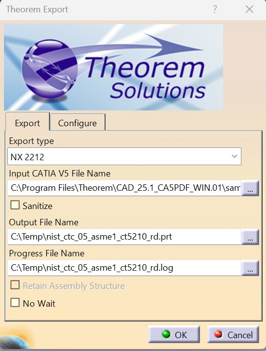
The Input CATIA V5 File Name, Output File Name and Progress File Name fields will be prepopulated if a model is already loaded into the CATIA V5 session. However, these locations can all be modified prior to selecting the OK button.
The Configure tab allows a configuration file to be given to the translation containing any additional arguments specified by the user. The options seen from within this configure panel will mirror those configurations created within the Theorem Unified Interface.
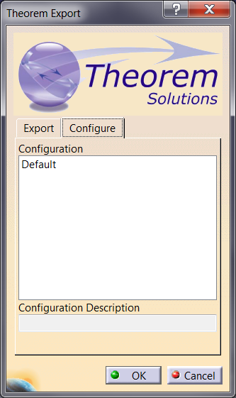
On selecting OK on the Export Panel the active Part or Assembly will be written to NX using the selected output directory.
Theorem Import
Once CATIA V5 has been started, NX data can be loaded into CATIA V5.
In order to import, the user selects the File -> Theorem Import Menu Option:

Which in turn launches the Theorem Import panel:
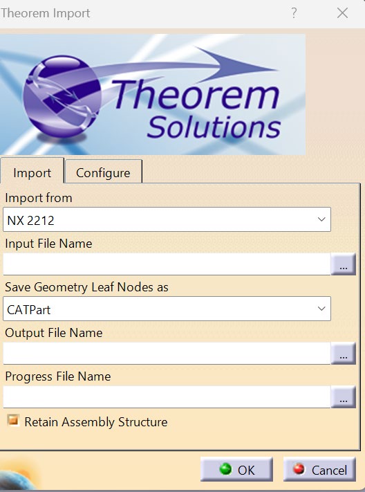
The Import From option allows the user to select the version of NX to import from.
The Input File Name option allows the selection of a NX .prt file. The Output File Name and Progress File Name fields will be populated when a model is selected and will, by default, save the associated files in the same directory as the NX part. Import Geometry Format allows the choice of CATPart or CGR for the translation output.
The Configure tab allows a configuration file to be given to the translation containing any additional arguments specified by the user. The options seen from within this configure panel will mirror those configurations created within the Theorem Unified Interface.
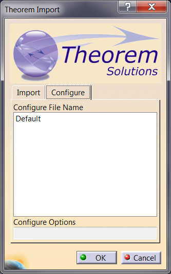
On selecting OK on the Import Panel the NX data will be imported into CATIA V5 and the data saved using the input into the selected output directory.
Translating Interactively from within NX
The NX to CATIA V5 translator allows an active NX Part or Assembly to be translated directly into CATIA V5 or a CATIA V5 Part or assembly to be imported, directly from the NX application.
In order to translate from within NX, the NX application must be started from within a Theorem environment, so that the appropriate NX menus are loaded.
NX can be started from a desktop shortcut, if requested at installation time. Alternatively, it can be started via the script provided in the CADverter installation at:
<installation_directory>\bin\RunNX[version].cmd
(where [version] should be substituted for the version of NX that you have installed – e.g. 2007, 2206 & 2212):
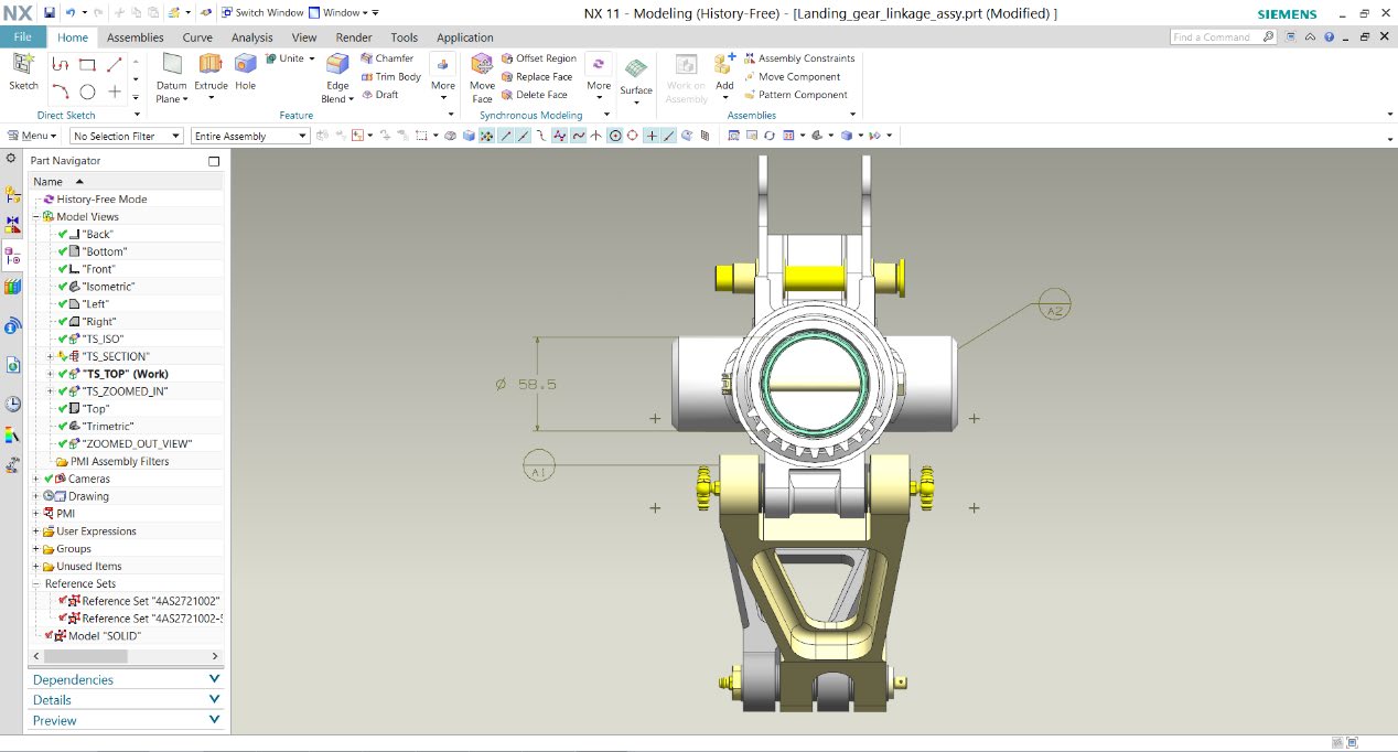
Theorem Export
Once NX has been started and a model loaded, the active Part or Assembly can be exported to CATIA V5.
In order to export, the user selects the File -> Export Menu. There are then 2 Export options:
Theorem Interactive Export to CATIA RXX (As Saved) – This is for use with data saved on a file system
Theorem Interactive Export to CATIA RXX (TeamCenter Loaded) – This is for use with data loaded from TeamCenter
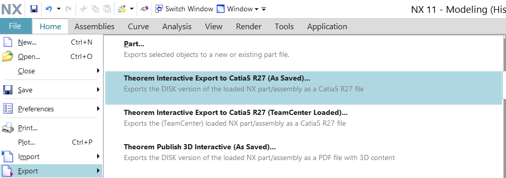
Once an option is selected the Theorem Export panel opens:
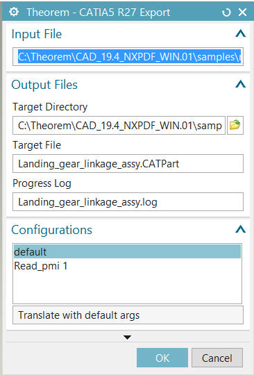
The Input File, Output File > Target Directory and Progress Log fields will be prepopulated if a model is already loaded into the NX session. However, these locations can all be modified prior to selecting the OK button.
The Configurations tab allows a configuration file to be given to the translation containing any additional arguments specified by the user. The options seen from within this configure panel will mirror those configurations created within the Theorem Unified Interface.
On selecting OK on the Export Panel the active Part or Assembly will be written to CATIA V5 using the selected output directory.
Theorem Import
Once NX has been started and a new model opened, CATIA V5 data can be loaded into NX.
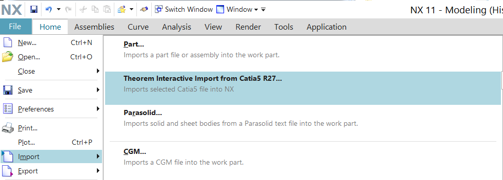
In order to import, the user selects the File -> Import -> Theorem Interactive Import from CATIA5 RXX Menu Option:
Which in turn launches the Theorem Import panel:
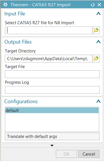
The Select CATIA5 RXX file for NX Import option allows the selection of a CATIA V5 part. The Target File and Progress Log fields will be populated when a model is selected and will, by default, save the associated files in the same directory as the V5 part.
The Configurations tab allows a configuration file to be given to the translation containing any additional arguments specified by the user. The options seen from within this configure panel will mirror those configurations created within the Theorem Unified Interface.
On selecting OK on the Import Panel the NX data will be imported into CATIA V5 and the data saved using the input into the selected output directory.
CATIA V5 Configuration
Introduction
This section details how to define and configure the CATIA V5 and Theorem environment to work together.
Conventions
Release of CATIA V5
To indicate a release of CATIA V5 the notation <XX> shall be used. This needs to be replaced with the specific release to be used i.e. 29, 30, 31, 32 & 33.
Platform specific directory
Within the installation directory of CATIA V5 there is a platform specific directory i.e. win_b64. This directory shall be referred to as <OSDS> in this section.
Theorem Installation directory
The Theorem translator installation directory is set at installation time in the translator ts_env.bat
file. This directory shall be noted as <%TS_INST%> in this section.
CATIA V5 Installation Directory
Upon installation of a CATIA V5 product the user will be asked to specify the installation directory. This is the directory which contains the platform specific <OSDS> directory.
Having selected the CATIA V5 installation directory via the browse button, the installation process
will record the location of the CATIA V5 installation directory in the ts_env.bat file. This file is located
in the Theorem translator installation directory. If the location of CATIA V5 subsequently changes,
the translator can be guided to the changed location by modifying this file using a text editor to
modify the ts_env.bat that is located in the translator installation directory.
Running CATIA V5 Translators
Before running the translator the user must run CATIA V5 interactively at least once to configure the CATIA V5 environment and license settings. This can be achieved by running the catia5r<XX>_start script as follows:
%TS_INST%\bin\catia5r<XX>_start.cmd
Once CATIA has been run the Translator can run as described in the relevant product User Guide.
CATIA V5 Environment DIRENV & ENV
The default location for CATIA V5 to store its global environment files is in the global directory:
Windows XP:
C:\Documents and Settings\All Users\Application Data\DassaultSystemes\CATEnv
Windows 7 & 8:
C:\ProgramData\DassaultSystemes\CATEnvOr
%APPDATA%\CATEnv
You can find this location by running:
%CATIAV5_INST%\<OSDS>\code\bin\setcatenv -h
The environment files are named in the form CATIA.V5RN.B<XX>.txt
If when installing CATIA V5 the default environment file location was replaced with another location
then this location needs to be indicated to the CADverter by defining in the ts_env.bat the
environment variable CATIAV5_DIRENV:
set CATIAV5_DIRENV=/some/directory
If the Theorem installation is needed to support multiple releases of CATIA, then the user can define release specific locations using:
set CATIAV5R<XX>_DIRENV=/some/directory
The Theorem translator will attempt to create its own environment file called
TheoremCatia5R<XX>.txt. The user must therefore have write permission to the CATEnv directory. If
this is not possible an existing environment file can be specified using the variable CATIAV5_ENV.
e.g.
set CATIAV5_ENV=CATIA.V5R27.B27
Note: the extension .txt is not required. The user can specify a release specific name using
CATIAV5R<XX>_ENV e.g.
set CATIAV5R19_ENV=CATIA.V5R27.B27
Checking the CATIA V5 Environment
A script is provided to check that the CATIA V5 environment is set up correctly. In a command window run the command script:
%TS_INST%\bin\checkcatia5r<XX>env.cmd