User Guide
Translating Interactively from within 3DExperience
Launching 3DExperience with Theorem Plug-ins
The 3DExperience to JT translator allows an opened 3DExperience part or assembly to be exported directly to JT, and for a JT part or assembly to be imported directly into the 3DExperience application.
In order to translate from within 3DExperience, the application must be started using a Theorem environment, so that the appropriate Theorem partner plug-ins are available. (See 3DExperience Environment files)
3DExperience can be started from a desktop shortcut created during installation.
Alternatively, it can be started via the script provided in the Translator installation located in:
<installation_directory>\bin
The script name is:
start_3DEXPERIENCE_Theorem_Multi-CAD_JT_CATIAV6R<version>.cmd
(where <version> should be substituted for the version of 3DExperience that you have installed – e.g. 2021x, 2022x, 2023x)
Interactive Export to JT
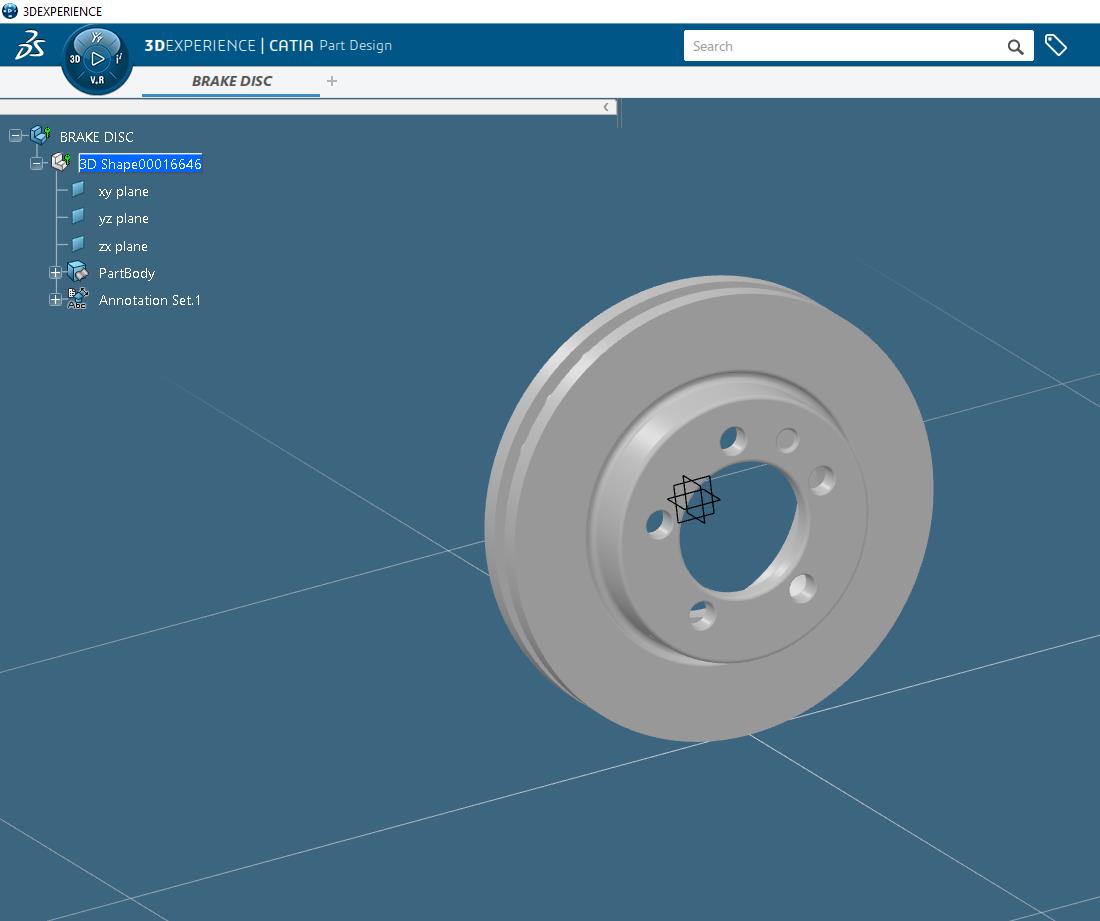
Once the 3DExperience application has been launched, open the product or representation that is going to be exported to JT.
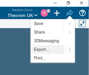
Select the arrow in the top right corner, then from the list displayed select Export.
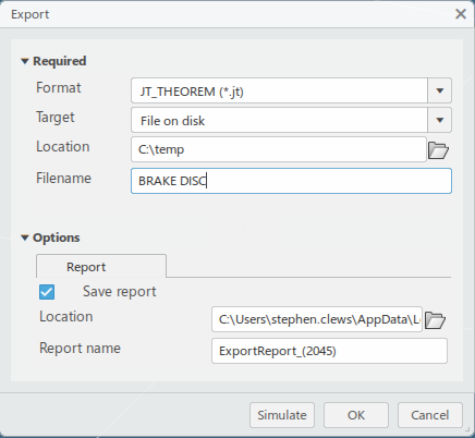
In the Export dialog box displayed, ensure the ‘Format’ is set to JT_THEOREM (*.jt/*.plmxml/*.stpx). Select the required location for the file and ensure the Filename displayed is correct. Click OK to initiate the export to JT.
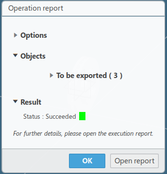
Export status of Succeeded displayed in Operation report window. JT files created in the location specified.
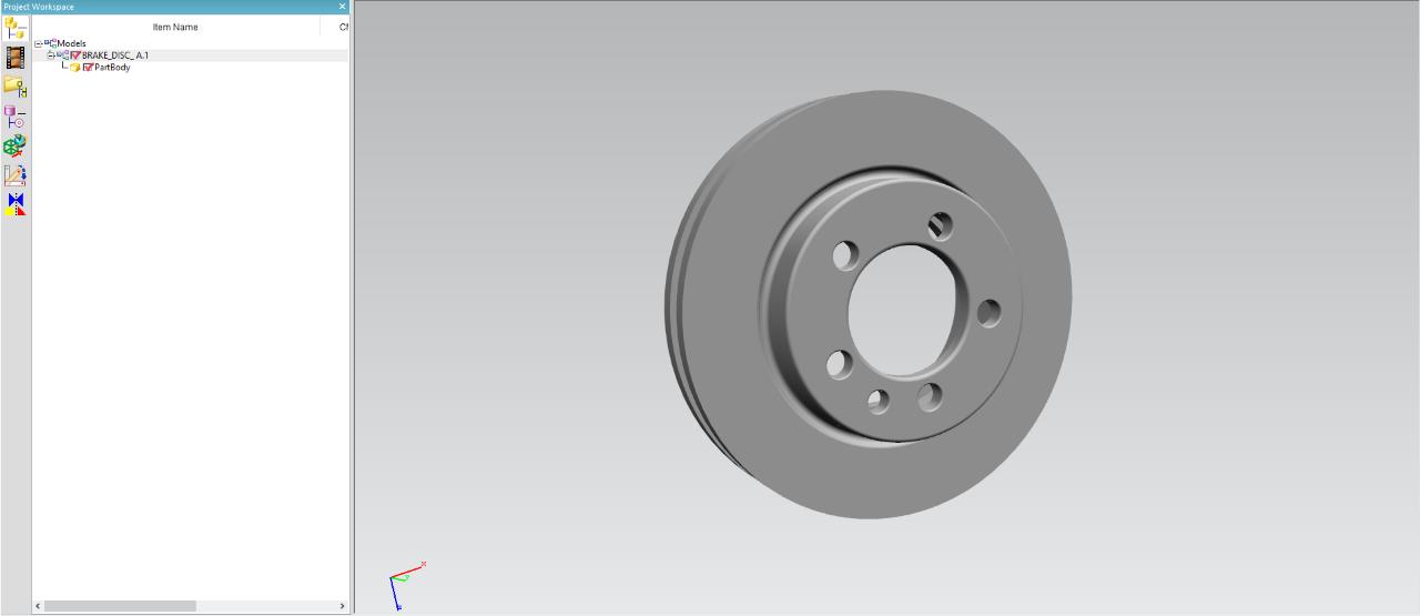
Interactive Import to 3DExperience
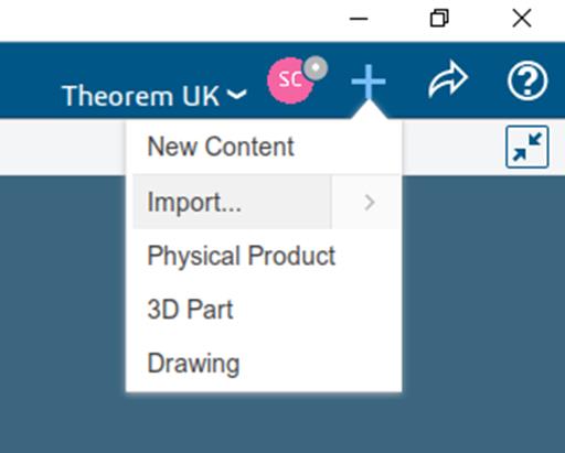
Once the 3DExperience application has been launched, it is possible for a model to be imported from JT. To do this select the ‘+’ icon in the top right corner, then from the list displayed select import.
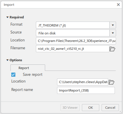
In the Import dialog box displayed, ensure the ‘Format’ is set to JT_THEOREM (*.jt/*.plmxml/*.stpx). Click on the folder icon next to the Filename field and choose the required JT file, then click OK to initiate the import to 3DExperience.
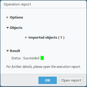
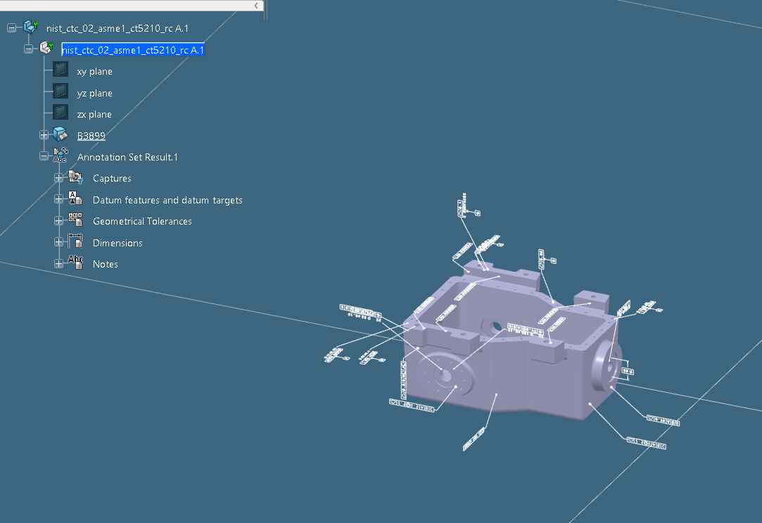
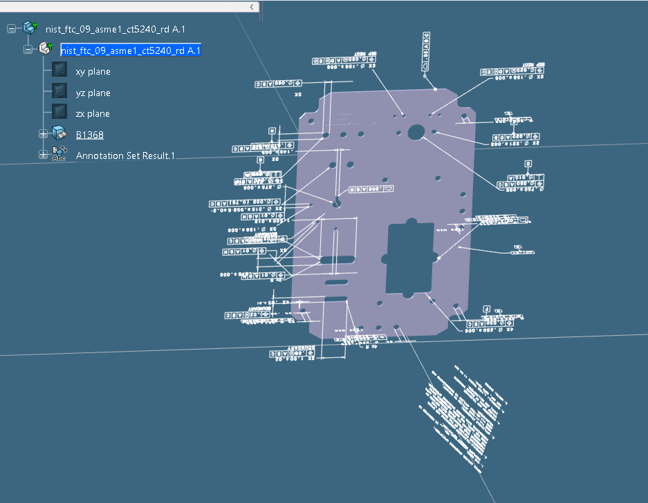
Import status of Succeeded displayed in Operation report window. Imported data saved into the 3DExperience database and opened into a new tab in the user’s session.
Theorem Interactive Conversion Settings
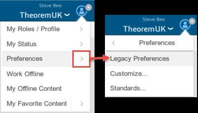
The 3DExperience interface does not currently require the user to apply any specific settings for the translation. There are some general settings that should be checked if required (e.g. for PMI conversion.) These are accessed through Preferences > Legacy Preferences > General > Compatibility > External Native 3D Formats.
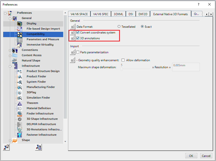
This page is a standard Dassault Page that sets the preferred mode of conversion (in this case Exact), and also the general options ‘Convert coordinates system’ and ‘3D annotations’. Both of which are toggled on.
There are also some Theorem settings that can be applied. These are accessed through Preferences > Legacy Preferences > Infrastructure > Theorem.
Two dedicated tabs under ‘Theorem’ allow the user access to Theorem Configurations for importing from JT and exporting to JT. From this Panel, the user can select a predefined configuration or create a new configuration.
To create a new configuration, select the ‘Launch Configuration Manager’ command.
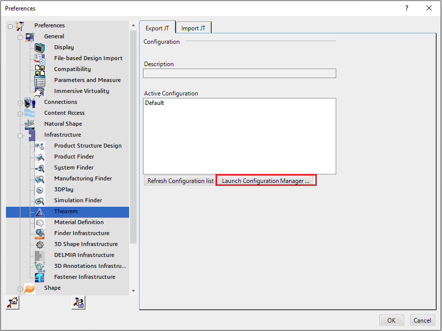
In the configuration manager window, select New, apply the relevant options, (see Configuration Manager), then rename the configuration as required.
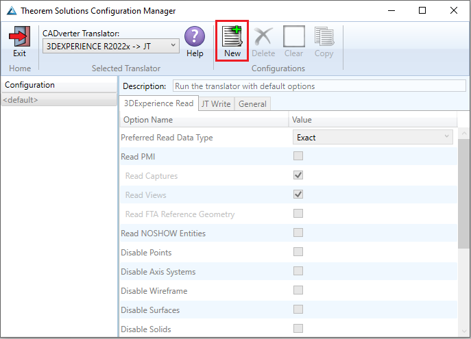
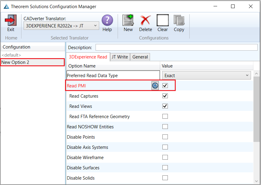
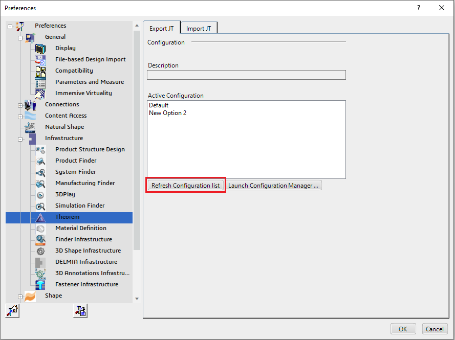
Any new configurations created will be displayed in the Active Configurations list once it has been refreshed. To do this select ‘Refresh Configuration list’.
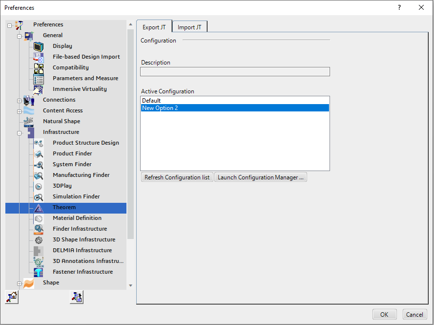
Select the required configuration to make it the active configuration. This will be highlighted in blue when selected.
Configuration Manager
3DExperience to JT
3DExperience Read
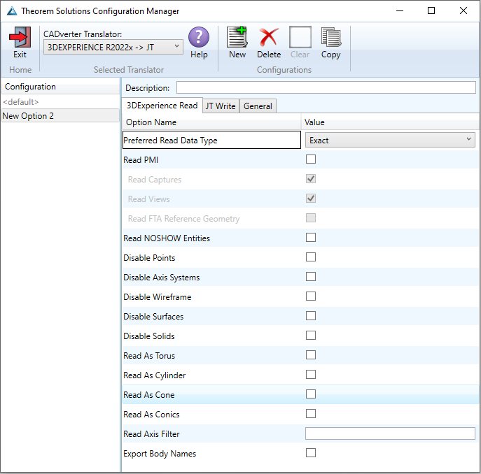
Each of the options displayed in the image above are described below:
Option |
Description |
|---|---|
Preferred Read Data Type |
The setting options are EXACT (default) or TESSELATED. Command Line Syntax:
|
Read PMI |
Enables PMI data read (Default is OFF.) Command Line Syntax:
Note – When ‘read_pmi’ is enabled it also enables the ‘fill_pmi_arrows’, ‘fill_pmi_text’ and ‘pmi_filled_text’ options. These can be overridden by setting the Advanced arguments ‘dont_fill_pmi_arrows’ and/or ‘dont_fill_pmi_text’. |
Read Captures |
A secondary argument to ‘Read PMI’ and allows control over whether captures are read as part of the process. Default is ON when ‘Read PMI’ is marked as ON. Captures can ONLY be read when ‘Read PMI’ is ON. Command Line Syntax:
|
Read Views |
A secondary argument to ‘Read PMI’ and allows control over whether views are read as part of the process. Default is ON when ‘Read PMI’ is marked as ON. Views can ONLY be read when ‘Read PMI’ is ON. Command Line Syntax:
|
Read FTA Reference Geometry |
A secondary argument to ‘Read PMI’ and enables the reading of FTA Reference Geometry. Default is OFF. FTA Reference Geometry can ONLY be read when ‘Read PMI’ is ON. Command Line Syntax:
|
Read NOSHOW Entities |
Read any entities that are in NOSHOW. Default is not to read NOSHOW entities. Command Line Syntax:
|
Disable Points |
Switches off Point processing. Command Line Syntax:
|
Disable Axis Systems |
Switches off Axis System processing. Command Line Syntax:
|
Disable Wireframe |
Switches off Wireframe processing. Command Line Syntax:
|
Disable Surfaces |
Switches off Surface processing. Command Line Syntax:
|
Disable Solids |
Switches off Solids processing. Command Line Syntax:
|
Read As Torus |
Read Toroidal surfaces in analytical form (default is NURBS.) Command Line Syntax:
|
Read As Cylinder |
Read Cylindrical surfaces in analytical form (default is NURBS.) Command Line Syntax:
|
Read As Cone |
Read Cone surfaces in analytical form (default is NURBS.) Command Line Syntax:
|
Read As Conics |
Read surfaces generated from a Conic in analytical form (default is NURBS.) Command Line Syntax:
|
Read Axis Filter |
Enables a specified list of axis systems to be processed. Command Line Syntax:
Where <value> is the name of the axis system. This can be formatted as per the examples below:
Multiple axis systems can also be processed. This is formatted as per the example below:
|
Export Body Names |
Maintains body names for parts that consist of multiple bodies. Command Line Syntax:
|
JT Write
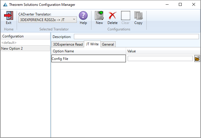
Each of the options displayed in the image above are described below:
Option |
Description |
|---|---|
Config File |
Allows a JT configuration file to be specified. “<TS_INST>/etc/tess.config” is the default. (See JT Configuration File for config file options.) Command Line Syntax:
|
General
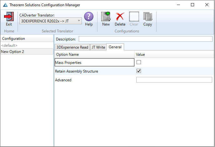
Each of the options displayed in the image above are described below:
Option |
Description |
|---|---|
Mass Properties |
Allows mass property information to be read. Command Line Syntax:
|
Retain Assembly Structure |
Enables Assembly Structure to be retained. (Default is ON.) Disabling this option will remove all assembly structure and collapse ALL geometry into a single selectable object. Command Line Syntax:
|
Advanced |
Allows any advanced arguments to be added to the configuration manager and applied during the translation. |
JT to 3DExperience
JT Read
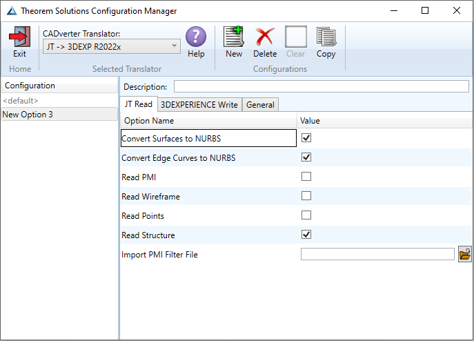
Each of the options displayed in the image above are described below:
Option |
Description |
|---|---|
Convert Surfaces to NURBS |
Read XT Brep surfaces as NURBS surfaces (else read in native form). Default is ON. |
Convert Edge Curves to NURBS |
Read XT Brep edge curves as NURBS curves (else read in native form). Default is ON. |
Read PMI |
Reads 3D PMI. Default is OFF. |
Read Wireframe |
Reads JT wireframe data. Default is OFF. |
Read Points |
Reads JT point data. Default is OFF. |
Read Structure |
Read assembly tree structure. Default is ON. |
Import PMI filter file |
Supply PMI filter file. “<TS_INST>/data/jt/jt_pmi_filter.txt” is the default. (See PMI Type Filter for more information on PMI Filter Files.) |
3DExperience Write
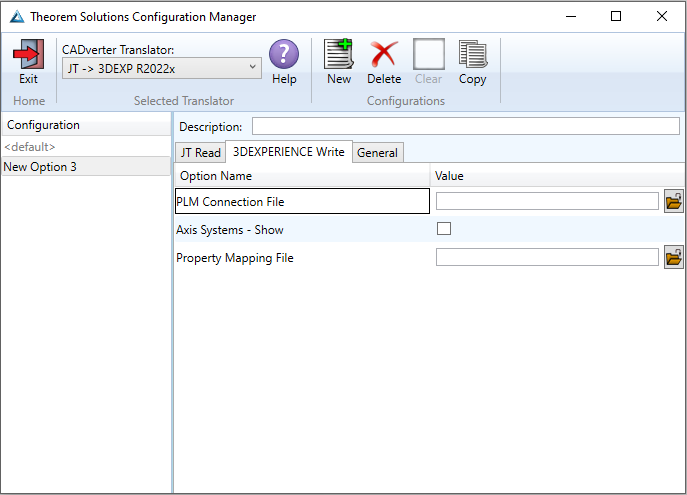
Each of the options displayed in the image above are described below:
Option |
Description |
|---|---|
PLM Connection File |
The PLM Connection file is one of the xml files defining the connection parameters to the PLM database. It is required to create a connection and logging into a PLM session programmatically. |
Axis Systems - Show |
Show all the axis systems on the imported object in 3DExperience. |
Property Mapping File |
Map CAD properties using a mapping file. (See Property Mapping Files for more information on Property Mapping Files.) |
General
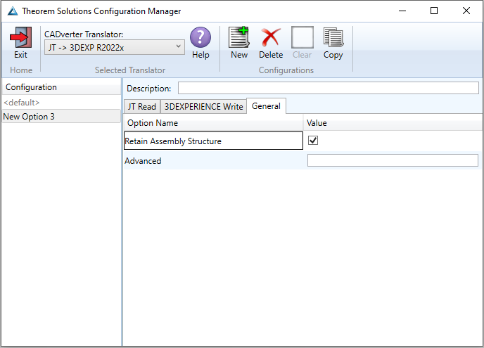
Each of the options displayed in the image above are described below:
Option |
Description |
|---|---|
Retain Assembly Structure |
Enables Assembly Structure to be retained. (Default is ON.) Disabling this option will remove all assembly structure and collapse ALL geometry into a single selectable object. |
Advanced |
Allows any advanced arguments to be added to the configuration manager and applied during the translation. |
Translating in Batch using CATUtil – DataExchangePLMBatch
Launching DataExchangePLMBatch
The Dassault Systemes CATUtil Batch Monitor tool can be launched with the correct Theorem enabled environment using the scripts provided in the Translator installation at:
<installation_directory>\bin\start_CATUTIL_Theorem_Multi-CAD_JT_CATIAV6R<revision>.cmd
(where <revision> should be substituted for the version of 3DExperience that you have installed – e.g. 2021x, 2022x, 2023x.)
It can also be started from the Tools > Utility workbench within an Interactive 3DExperience session.

In some cases, it may be desirable to ignore the interactive settings while translating using DataExchangePLMBatch.
This can be achieved by setting the following variable in the Theorem CATEnv file:
TS_IGNORE_JT_CATSETTINGS=1
Batch Export to JT
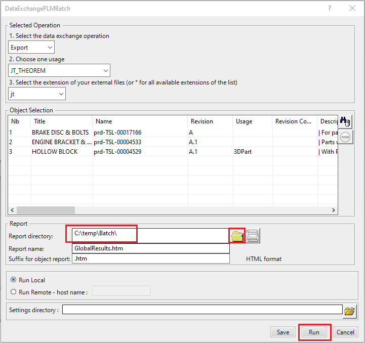
Here is an example showing what is required in preparation for a 3DExperience database selection and batch export.
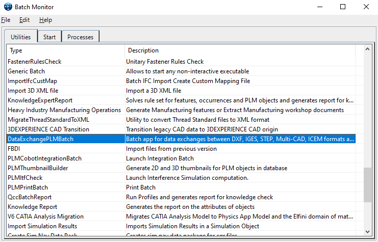
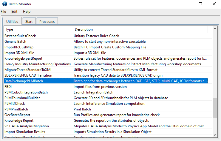
Double click on DataExchangePLMBatch.
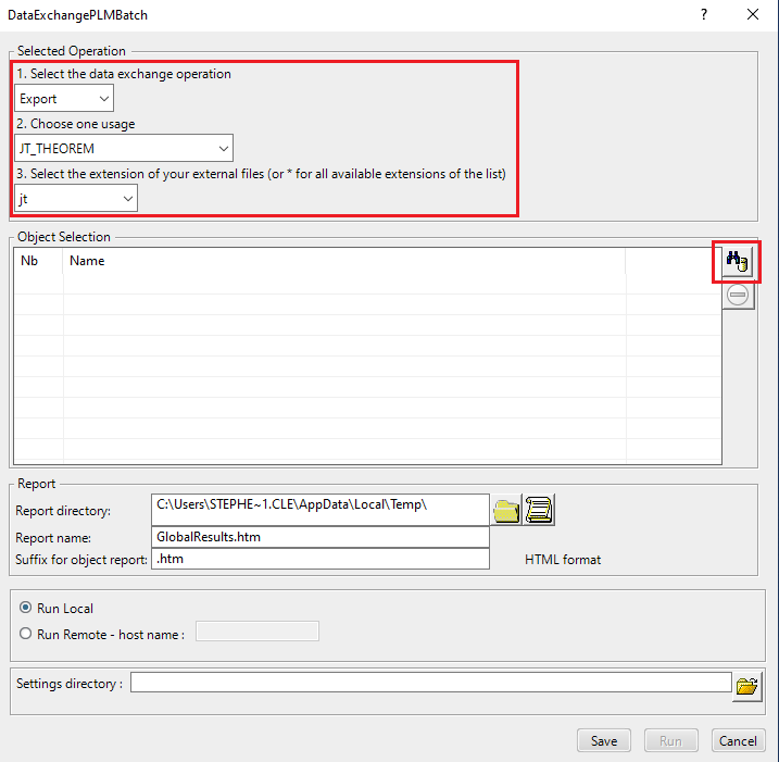
Ensure that ‘Export’ is selected as the data exchange operation, ‘JT_THEOREM’ is selected as the usage and ‘jt’, ‘plmxml’ or ‘stpx’ is selected as the extension.
To add the required products for the batch export, select the 3DExperience Platform Object Search icon.
In the subsequent window displayed, add the required products using the correct attribute, operator and value ensuring that the correct object type has been selected. (E.g. Physical Product). Where required use an Asterix in the value field to identify multiple parts or assemblies.
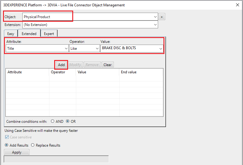
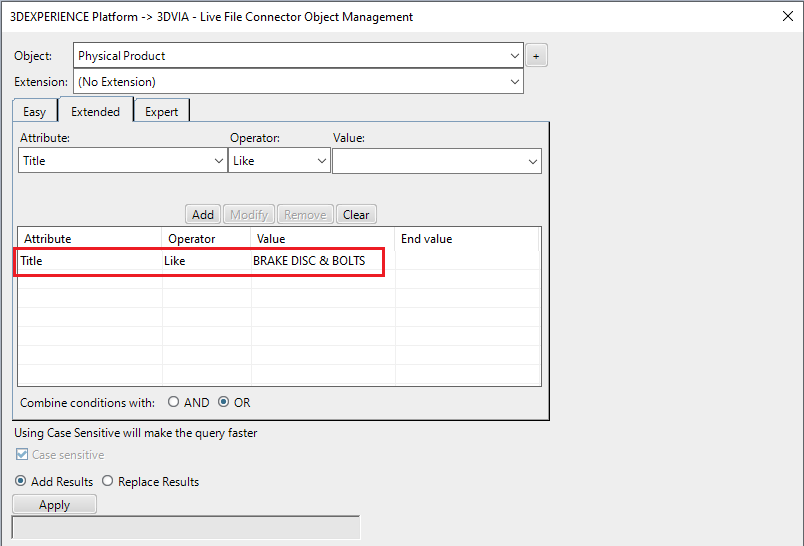
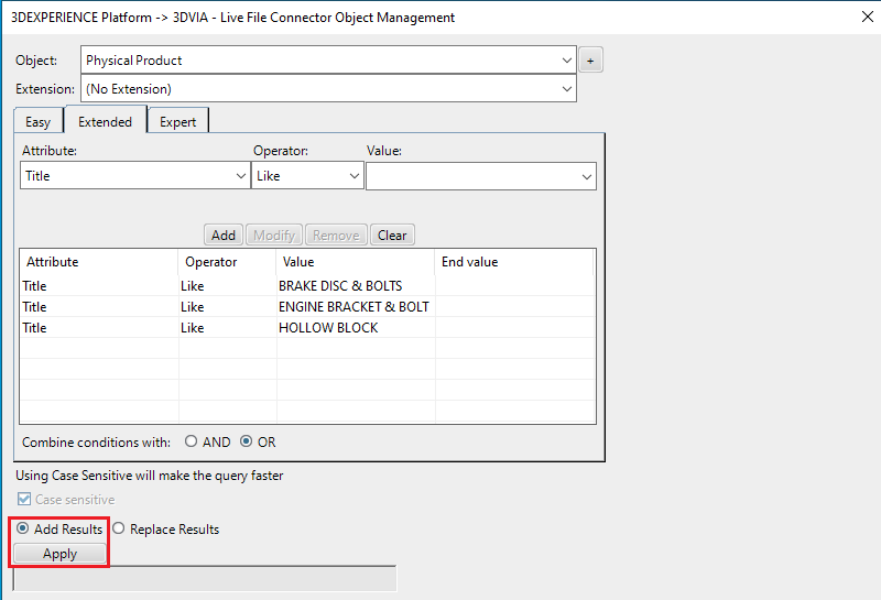
For multiple products ensure that the OR condition has been selected. Select Add results and click Apply to add the list of products to the Object Selection field.
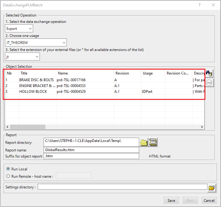
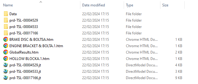
To change the location where both the report and the JT files will be saved, select the icon next to the Report directory field, then select the required directory.
Click Run to initiate the Batch Export.
Batch Import from JT
Here is an example showing what is required in preparation for a JT file selection and batch import.
Double click on DataExchangePLMBatch.
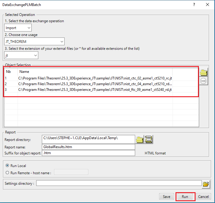
Ensure that ‘Import’ is selected as the data exchange operation, ‘JT_THEOREM’ is selected as the usage and ‘jt’, ‘plmxml’ or ‘stpx’ is selected as the extension.
To add the required products for the batch import, select the 3DVIA – Live File Connector Object Search icon, next to the Object Selection field.
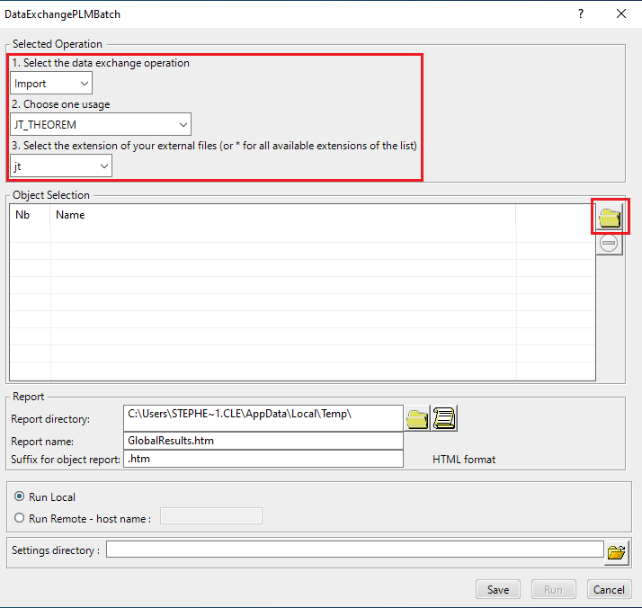
In the subsequent window displayed, add the products by clicking on Member and selecting the required JT files.
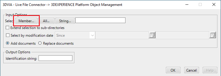
These will then be added to the Object Selection field.
Click Run to initiate the Batch Import.
Imported data saved into the 3DExperience database.

Changing the Options Selected for a Batch Export / Import
The default options selected for a batch export and import can be modified within the xcad_jt_opts.txt file and jt_xcad_opts.txt file respectively. Both files are available in the following location.
<installation_directory>\data\jt
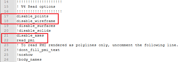
Within the xcad_jt_opts.txt file a number of arguments are displayed, these include common arguments such as read_pmi, disable_points, disable_wireframe and disable_axes which are all turned off by default. If an argument has the character (!) at the start of the line then this means that the argument is turned off.
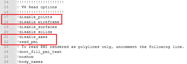
To turn on a particular argument remove the (!) character from that particular line. Consequently to turn off an argument add the (!) character to the start of the line. Please note that the user will need to be in administrator mode in order to make the change.
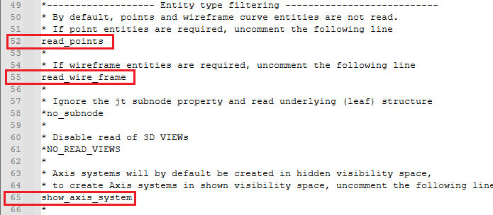
Within the jt_xcad_opts.txt file a number of arguments are also displayed, these include read_points, read_wire_frame and show_axis_system which are all turned off by default. If an argument has the character (*) at the start of the line then this means that the argument is turned off.
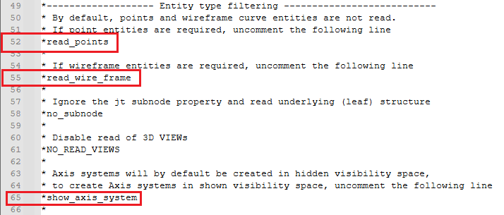
Once again, to turn on a particular argument remove the (*) character from that particular line. Consequently to turn off an argument add the (*) character to the start of the line. Please note that the user will need to be in administrator mode in order to make the change.
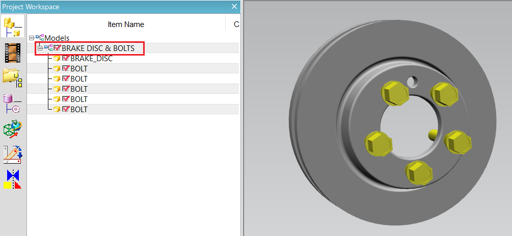
Please note that when exporting data using DataExchangePLMBatch, ensure that the design_name option has been turned on in the xcad_jt_opts.txt file. If this option is turned off then the root node displayed in the JT output will be named the object name displayed in 3DExperience, (this is a 3DExperience generated name/number). The design_name option is turned OFF by default.

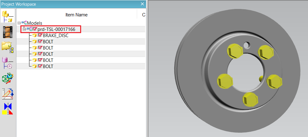
If the design_name option is turned on then the root node displayed in the JT output will be named the object title displayed in 3DExperience, (this is a user generated name/number). Turning on the design_name option will also generate a monolithic JT output.

Changing the JT Configuration Selected for a Batch Export
The JT configuration file selected for a batch export can also be modified within the xcad_jt_opts.txt file.
To change the JT configuration, simply remove the existing file path displayed and replace it with the new file path. The JT configuration argument will be displayed under the JT Write options section in the xcad_jt_opts.txt file. Note – ensure that the -z character is not removed.


These changes will consequently mean that the user specified JT configuration will be used instead of the default JT configuration when translating via DataExchangePLMBatch. Please note that the user will need to be in administrator mode in order to make the change.
Translating on the Command Line
It is possible to run a 3DExperience to JT translation on the command line, however as all CAD data is saved in the 3DExperience database an XML file will need to be used as the input file instead of a CAD file. This XML file contains all the necessary information to locate, open and translate the CAD data. This is explained in more detail below. In order to run a translation on the command line the following is required:
<TS_INST>\bin\catia6r<revision>_jt.cmd <input_file> -o <output_file> -z <config_file> <options>
Where:
<TS_INST> is the Theorem Solutions software installation directory.
<revision> is the version of 3DExperience that you have installed – e.g. 2021x, 2022x, 2023x.
<input_file>
Is an xml file defining access to a specific object in the 3DExperience database.
This file provides user login details (V6R2013x) or a Login Ticket (2015x onwards) (see Creating a Login Ticket), to
a specified Enovia repository plus a set of 3 attribute names and values which will uniquely identify
the input object required for the conversion. Example XML files can be found in the
<TS_INST>\samples\3dexperience folder. These can be modified and saved on your local drive.
Here is an example of the xml input file for 3DExperience:
<?xml version="1.0" encoding="utf-8"?>
<mc6_read>
  <!-- parameters must be in this ORDER -->
  <!-- parameters only the value passed to V6 -->
  <parameters>
    <attribute name="repository" value="PLM1"/>
    <attribute name="ServerName" value="3dspace.theorem.com"/>
    <attribute name="ServerPort" value="447"/>
    <attribute name="ServerRootURI" value="3dspace"/>
    <attribute name="LoginTicket"
      value="REEyNzM3M0Q1REM2NDgxQzlFNzk1QzIwNjZGRDYzODN8Um9iaW58Um9iaW58fHwwfA=="/>
    <attribute name="PLMType" value="VPMReference"/>
    <attribute name="ReportDirectory" value="C:\TEMP\V6Export"/>
    <attribute name="LicenseData" value="LIC"/>
    <attribute name="BatchXMLFileName" value="Default"/>
  </parameters>
  <!-- arguments both key and value are passed to V6 -->
  <arguments>
    <attribute key="PLM_ExternalID" value="prd-TSL-00004525"/>
    <attribute key="V_version" value="A"/>
    <attribute key="minorrevision" value="1"/>
  </arguments>
</mc6_read>
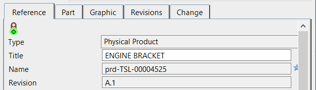
The PLM_ExternalID value will be the Name displayed in the properties of the object selected in 3DExperience.
Note
In some cases, the “minorrevision” value is not required in the XML file, only the V_version value is required, which is the Revision displayed in the properties of the object selected in 3DExperience. This value could be A.1 for example.
-o <output_file> – Is the required JT output file name.
-z <config_file> – Is the name of the JT configuration file used for controlling the output characteristics
described in JT Configuration File. -z <config_file> not required in the command line if using the default configuration.
<options> – Options displayed in the configuration manager can be added at the end of the command using the correct syntax, e.g. disable_points, disable_wireframe. (See Configuration Manager, 3DExperience to JT Export for list of command line syntaxes.)

Log File Generation
Export Process Log Files
In the process of exporting the selected 3DExperience part or assembly, the following log files are generated by the JT Export plug-in.
.errfile – gives the full processing list of errors, warnings and information.rptfile – gives a short list of the entities created and failed.log.summaryfile – gives the times for start and finish and the status message code (these can be customised).logfile – gives a single file with the data from all three logs
The process log and error messages are, by default, located in the 3DExperience CATReport directory, e.g.
C:\Users\<user>\AppData\Local\DassaultSystemes\CATReport
Where <user> is your user name
The files are named the same as the part or assembly being exported e.g. ENGINE_BRACKET would produce the following log file names:
ENGINE_BRACKET.errENGINE_BRACKET.rptENGINE_BRACKET.log.summaryENGINE_BRACKET.log
Additional log files are created in the TSC_TEMP_DIR directory. This directory is defined in the
%TS_INST%\ts_env.bat file.
%TSC_TEMP_DIR%\Read_to_viewer_<input_part_name>.log
Where <input_part_name> is the name of the input part (or the active part name in interactive usage)
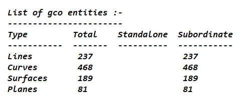
This contains information describing the 3DExperience ‘data read’ processing into Theorem Intermediate data format. Normally a list of entities.
%TSC_TEMP_DIR%\viewer_<part-name>_screen_output.log
Where <part-name> is the selected output file name.
This contains the screen output of the process of writing the data to JT. The status of the translation can be found here.
%TSC_TEMP_DIR%\viewer_<part-name>.log
Where <part-name> is the selected output file name.
This contains detailed process information of the write of the data to JT and contains additional information such as modifiers and options used.
Import Process Log Files
In the process of importing a JT file, the following log files are generated by the JT Import plug-in. These are the same types of files produced when exporting from 3DExperience.
.errfile.rptfile.log.summaryfile.logfile
The process log and error messages are, by default, located in the 3DExperience CATReport directory, e.g.
C:\Users\<user>\AppData\Local\DassaultSystemes\CATReport
Where <user> is your user name
The files are named after the selected input file name. e.g. nist_ftc_08_asme1_ct5240_rc.jt would produce the following log file names:
nist_ftc_08_asme1_ct5240_rc.errnist_ftc_08_asme1_ct5240_rc.rptnist_ftc_08_asme1_ct5240_rc.log.summarynist_ftc_08_asme1_ct5240_rc.log
3DExperience Environment Files
As part of the Theorem installation process, a set of 3DExperience environment files are created which are subsequently used in the launch of 3DExperience and CATUtil sessions to support the Theorem partner plug- ins for JT import and export.
A ‘CATEnv’ file is created for each installed version of 3DExperience.
These environment files are located in the 3DExperience revision specific folder e.g.
<installation_directory>\B423\win_b64\CATEnv\Theorem_Multi-CAD_JT_CATIAV6R2021x.txt<installation_directory>\B424\win_b64\CATEnv\Theorem_Multi-CAD_JT_CATIAV6R2022x.txt<installation_directory>\B425\win_b64\CATEnv\Theorem_Multi-CAD_JT_CATIAV6R2023x.txt
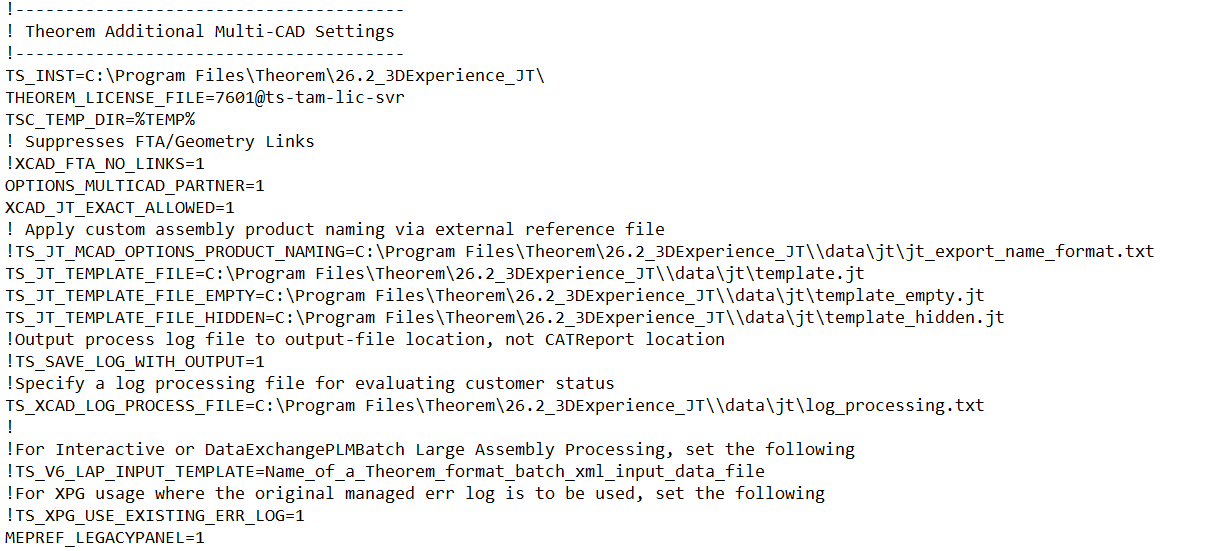
These files consist of the current 3DExperience settings with the required Theorem settings appended at the bottom.
JT Configuration File
Introduction
A configuration file contains the settings for your translations. The configuration file can be specified using the command line option -z.
For interactive users the configuration file name can be defined in the
Preferences > Legacy Preferences > Infrastructure > Theorem form, which in turn points to the
TS_INST\data\jt\jt_mcad_options_configuration_v6.txt file (where TS_INST = the Theorem Installation folder).
By default, this is set to TS_INST\etc\tess.config
Alternatively, if translating using DataExchangePLMBatch, with the environment variable
TS_IGNORE_JT_CATSETTINGS=1 set, the interactive Preferences > Legacy Preferences > Infrastructure > Theorem
form will be ignored, and the content of the TS_INST\data\jt\xcad_jt_opts.txt file will be used.
In this file, the default is also defined as
"%TS_INST%\etc\tess.config"
The JT configuration file contains various sections, each containing different settings based on the section.
The Setup Section
The setup options in the configuration file define how your files are translated. The setup section is the first part of the configuration file and contains a series of standard translator options.
To edit setup options:
Open an existing configuration file with a text editor.
Edit the configuration file options listed in the table below.
Save the configuration with a .config extension.
Option name |
Keywords |
Example |
|---|---|---|
EAITranslator |
EAITranslator { |
EAITranslator { |
OutputDirectory |
“path to directory” |
OutputDirectory = “/home/<user>/” |
CommonPartsPath |
“path to directory” |
CommonPartsPath = “/myaccount/jtparts/” |
chordalOption |
“RELATIVE” “ABSOLUTE” |
chordalOption = “RELATIVE” |
structureOption |
“PER_PART” “MONOLITHIC” “FULL_SHATTER” |
structureOption = “MONOLITHIC” |
WriteWhichFiles |
“ALL” “ASSEMBLY_ONLY” “PARTS_ONLY” |
WriteWhichFiles = “ALL” |
compression |
true / false |
compression = true |
triStripOpt |
true / false |
triStripOpt = false |
seamSewing |
true / false (Note: Not available for Unigraphics.) |
seamSewing = true |
seamSewingTol |
any integer |
seamSewingTol = 0.001 |
includeBrep |
true / false |
includeBrep = false |
brepPrecision |
“SINGLE” “DOUBLE” |
brepPrecision = “SINGLE” |
autoNameSanitize |
true / false |
autoNameSanitize = true |
updateChangedPartsOnly |
true / false |
updateChangedPartsOnly = false |
verboseReporting |
true / false |
verboseReporting = false |
writeAsciiAssembly |
true / false |
writeAsciiAssembly = false |
singlePartsNoAssem |
true / false |
singlePartsNoAssem = false |
smartLODgeneration |
true / false |
smartLODgeneration = true |
autoLowLODgeneration |
true / false |
autoLowLODgeneration = true |
numLODs |
any integer |
numLODs = 3 |
close brace |
The Level of Detail (LOD) Section
The level of detail section of the configuration file contains the tessellation and simplification information for each level of detail in the file.
This section consists of several sets of level of detail (LOD) information, and the number of these sets depends on the number you specified on the numLODs line in the configuration file.
To edit level of detail options:
Open an existing configuration file in a text editor.
Edit the configuration file options listed below.
Save the configuration with a .config extension.
Option name |
Keywords |
Example |
|---|---|---|
LOD |
LOD “lod number” { |
LOD “1” { |
Level |
any integer |
Level = 1 |
Chordal |
any number |
Chordal = 0.001 |
Angular |
any number |
Angular = 25 |
Length |
any number |
Length = 1 |
FeatureSuppression |
any integer |
FeatureSuppression = 0 |
Simplify |
any number |
Simplify = 0.60 |
close brace |
The Filter Section
The filter section of the configuration file contains the filename and metadata filtering information. Edit this section if you want to change how the translator sanitizes filenames and filters metadata keys.
To edit filter options:
Open an existing configuration file with a text editor.
Edit the configuration file options from the table below.
Save the configuration with a .config extension.
Option name |
Keywords |
Example |
|---|---|---|
Filter |
Filter { |
Filter { |
FilenameSanitizeSet |
“string of characters” |
FilenameSanitizeSet = |
FilenameSanitizeSetAdd |
“string of characters” |
FilenameSanitizeSetAdd = “4l” |
FilenameSanitizeSetDelete |
“string of characters” |
FilenameSanitizeSetDelete = “c” |
MetadataKey |
“string of characters” |
MetadataKey = “metadata key to exclude” |
close brace |
The Metadata Section
The metadata section sets which metadata to attach to all parts, assemblies and nodes of the model.
Note
Be sure to add these options to the configuration file in pairs: one line to define the metadata key and one line to define the metadata value.
To edit metadata options:
Open an existing configuration file (.CONFIG) in a text editor.
Edit the configuration file options shown in the table below.
Save the configuration with a .config extension.
Option name |
Keywords |
Example |
|---|---|---|
Metadata |
Metadata { |
Metadata { |
AddToParts |
“string of characters” |
AddToParts = “<metadata key>” / AddToParts = “<metadata value>” |
AddToAssemblies |
“string of characters” |
AddToAssemblies = “<metadata key>” / AddToAssemblies = “<metadata value>” |
AddToAllNodes |
“string of characters” |
AddToAllNodes = “<metadata key>” / AddToAllNodes = “<metadata value>” |
close brace |
Large Assembly Processing (LAP)
Overview
The export of large assemblies from 3DExperience to JT may be handled using the default process, or a new Large Assembly Processing method.
This new process is as follows:
The assembly is read from 3DExperience using the MultiCAD interfaces as normal, but only the assembly structure is directly converted to a main output jt file.
The reference to the geometry for each individual component part node in the assembly is written to separate .xml files. This part of the process takes minimal time and processing resource.
As each of the individual .xml files are created, an entry is made into a batch processing file to allow subsequent conversion of the geometry data into the output JT files required for the complete assembly.
LAP Options
The following option support has been added into the 3DExperience to JT product to support Large Assembly
Processing (LAP). This can be modified in the xcad_jt_opts.txt file.
Option |
Description |
|---|---|
struct_read (mandatory) |
This option causes only the CATIA assembly structure to be written to the specified output jt file. |
large_assy_process (mandatory) |
This option invokes the creation of separate intermediate data files representing each assembly ‘leaf node’ (component/part) containing the part geometry. This option should always be used with the ‘struct_read’ option. A batch command file (.bat) is also created and this contains a sequence of individual commands to convert the intermediate data files into the required jt files representing the part/component geometry. The default name for the generated batch file is <output_file_path>.bat, e.g if the output file name was C:\parts\jt\assembly1.jt, the batch file name would be C:\parts\jt\assembly1.bat. |
write_assembly_script (optional) |
This option allows the user to specify a non-default file name path for the batch command file generated by the large_assy_process option. |
autorun (optional) |
This option will cause the batch command script to be automatically invoked when the main conversion process ends. |
zpart (optional) |
This option specifies the name of a JT write config file to be used in the batch file conversions for creating the jt files representing the part geometry. This will override the -z option used for the main assembly conversion. |
Command Line Operation
The options for Large Assembly Processing can be used as command line options on the catia6_jt.cmd. (See Translating on the Command Line.)
Interactive Operation
The Large Assembly Processing facility can be used in interactive mode by including the required options in the
%TS_INST%\data\jt\xcad_jt_opts.txt file.
DataExchangePLMBatch Operation
The Large Assembly Processing facility can be used in DataExchangePLMBatch mode.
For Interactive or DataExchangePLMBatch Large Assembly Processing, set the following in the relevant environment file:
e.g. <installation_directory>\B424\win_b64\CATEnvTheorem_Multi-CAD_JT_CATIAV6R2022x.txt
TS_V6_LAP_INPUT_TEMPLATE=<XML File name>TS_PLM_PRODUCT_REF_TYPE_NAME=VPMReferenceTS_PLM_REPRESENTATION_TYPE_NAME=VPMRepReferenceWhere <XML File name> is the XML file used, e.g. 3dex_2022x_input_Engine_Bracket.xml. (See Translating on the Command Line for more information on XML Files.)
Property Mapping Files
The selections of the displayed JT Config File (.config), Property Mapping files and PMI Type Filter Files are set through the configuration file:
%TS_INST%\data\jt\jt_mcad_options_configuration.txt
The format of the jt_mcad_options_configuration.txt is:
<jt_config_files>
Default TessCATIA6MultiCAD;%TS_INST%\etc\tessCATIAV6MultiCAD.config
</jt_config_files>
<jt_import_property_files>
Default Import Jt Property Filter;%TS_INST%\data\jt\jt_v6_property_mapping.txt
</jt_import_property_files>
<jt_export_property_files>
Default Export Jt Property Filter;%TS_INST%\data\jt\v6_jt_property_mapping.txt
</jt_export_property_files>
<jt_import_pmi_files>
Default Import PMI Type Filter;%TS_INST%\data\jt\jt_pmi_filter.txt </jt_import_pmi_files>
There is one option menu entry per line containing <Description> ; <Absolute File Path>
Where the <Description> is the text to be displayed in the option menu and the file path is the location of the JT write configuration file or the property filter. This path definition can include environment variables.
The user can control the mapping of user defined attributes contained in the PLM part definition and external files during the import and export processes.
The ‘JT Import Property Mapping File’ and ‘JT Export Property Mapping File’ are text files of a format described below:
A mapping file is used to control which properties are converted by setting a control value. Setting the control value to 0 will stop a specific property from being exported.
The mapping file can also enable the mapping of property names to new names: this is performed by switching the name between the input name (= field 1) and the output name (= field 2).
The File Line Format is as follows:
SourceName, TargetName, Control, Dummy, Dummy, Dummy Lines beginning with a "#" are taken as comment lines
SourceName - is the input attribute name.
TargetName - is the output attribute name (NULL means use SourceName)
Control - is flag to control conversion: 0 - Do not convert, 1 - Do convert, Dummy - unused fields
If SourceName is given as NULL then any item not included in map will match
So to include all other attributes use
NULL,NULL,1,,,
Or to exclude all other attributes use
NULL,NULL,0,,,
Examples
To exclude the MPARTNAME attribute
MPARTNAME,NULL,0,,,
To include the TAG attribute
TAG,NULL,1,,,
To include the TAG attribute but under a different name, i.e. PART NUMBER
TAG,PART NUMBER,1,,,
PMI Type Filter
The user can control the filtering of PMI types on import from JT by specifying an appropriate filter file. A default filter file is provided with the installation located as %TS_INST%\data\jt\jt_pmi_filter.txt. This file contains a list of all PMI types by name and can be edited to exclude different named types by removing a ‘#’ (comment character) from the type not required to be imported.
e.g. if the file is edited as follows:
# File for filtering on PMI type via the command : pmi_filter_file "file name"
#
# Line Format:-
# "pmi type"
#
# Lines that start with a '#' are ignored.
# The supplied file contains all possible PMI types in alphabetical order preceded by a '#'
#
# To prevent a particular PMI type from being processed, remove the '#' from that type
#
#arc spot weld
#attribute note
#balloon
#bead
#bundle dressing note
#callout dimension
center point
#centerline
#cert
point
#chamfer
. . .
Any PMI entities of type ‘center point’ would NOT be imported.
This facility was introduced to reduce processing time due to large numbers of ‘redundant’ PMI entities in a JT file.
Note that default settings that can control the JT Export plugin, are also read from the data file %TS_INST%\data\jt\xcad_jt_opts.txt.
Default settings that can control the JT Import plugin, are also read from the data file %TS_INST%\data\jt\jt_xcad_opts.txt.
JT Template Files
If, when a representation is read from 3DExperience, no geometry is found in the representation, all the geometry is hidden or a major write error occurs preventing a JT file being produced, then a template JT file (named by default as template_empty.jt, template_hidden.jt and template.jt respectively) will be copied to the expected output file name.
This enables the conversion process to complete successfully and maintains the expected file outputs.
This behaviour is implemented via environment variables set in the Theorem CATEnv file e.g.
<installation_directory>\B424\win_b64\CATEnvTheorem_Multi-CAD_JT_CATIAV6R2022x.txt, typically as
follows:
TS_JT_TEMPLATE_FILE=C:\Program Files\Theorem\25.3\data\jt\template.jtTS_JT_TEMPLATE_FILE_EMPTY=C:\Program Files\Theorem\25.3\data\jt\template_empty.jtTS_JT_TEMPLATE_FILE_HIDDEN=C:\Program Files\Theorem\25.3\data\jt\template_hidden.jtThe user can change the content of these JT files, or their location and names as required.
Creating a Login Ticket
Use a browser link (similar to the one below) to your 3DExperience Server.
https://3dspace.2017x.theorem.com:447/3dspace/common/emxNavigator.jsp
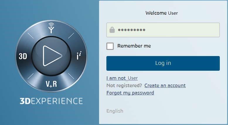
Login as normal, e.g.
User
Password
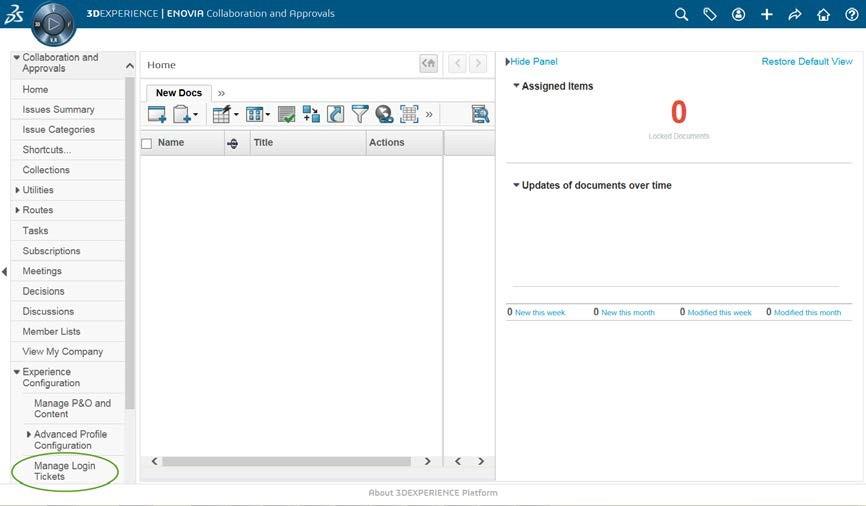
Select Collaboration and Approvals > Experience Configuration > Manage Login Tickets.
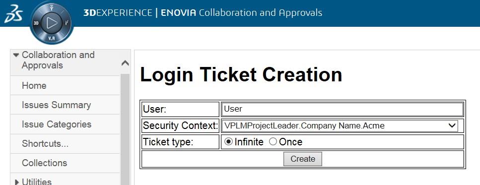
Select the values required for your user:
User and Security Context should already be set, make sure that Ticket Type ‘Infinite’ is selected. Then click on ‘Create’.
This will produce the ticket. See example below:
REEyNzM3STE1MER2NDgxQzlFNzk1QzIwNjZGNATzDAN8Um9iaW58Um9iaW58fHwwfA==
This can then be used as the ‘LoginTicket’ value explained previously.