User Guide
Publish 3D On-Demand
By default the Publish 3D for NX translator will translate source data using a default template.
This template can be used as a basis for a customer’s specific template design and illustrates fundamental capabilities of the translator with regard to publishing 3D data into a pre-defined document format.
More complex template examples are provided in the following the locations:
<installation_directory>\data\publish_3dpdf\
default_Manifest – Illustrates various Adobe capabilities
publishBlank – Illustrates publishing to a blank template
<installation_directory>\data\publish_3dpdf\templates\publishBOM – Illustrates how to output an Assembly Bill of Materials
publishMotion – Illustrates using CAD data with motion in PDF
publishViewer – Illustrates JavaScript additions to a template replicating a CAD viewer
publishECR – Illustrates a simple Engineering Change Request
publishRFQ – Illustrates a simple Request for Quotation
publishAttachments – Illustrates adding attachments to a template
These templates are supplied as examples only and can be used by customers as a guide to creating their own template documents.
Theorem offer a wide range of services to assist customers with their document creation needs. If you would like more information regarding our template design services please contact sales@theorem.com quoting “3D PDF Template Design”.
Default Publishing
Default Publishing – via the Unified Interface
The Unified Interface can be started via the Start Menu or desktop – if shortcuts were added during installation.
Alternatively, the Unified Interface can be run via a Windows Explorer selection in:
<UI_installation_directory>\bin\Unified_Interface.cmd
The following interface will be launched:
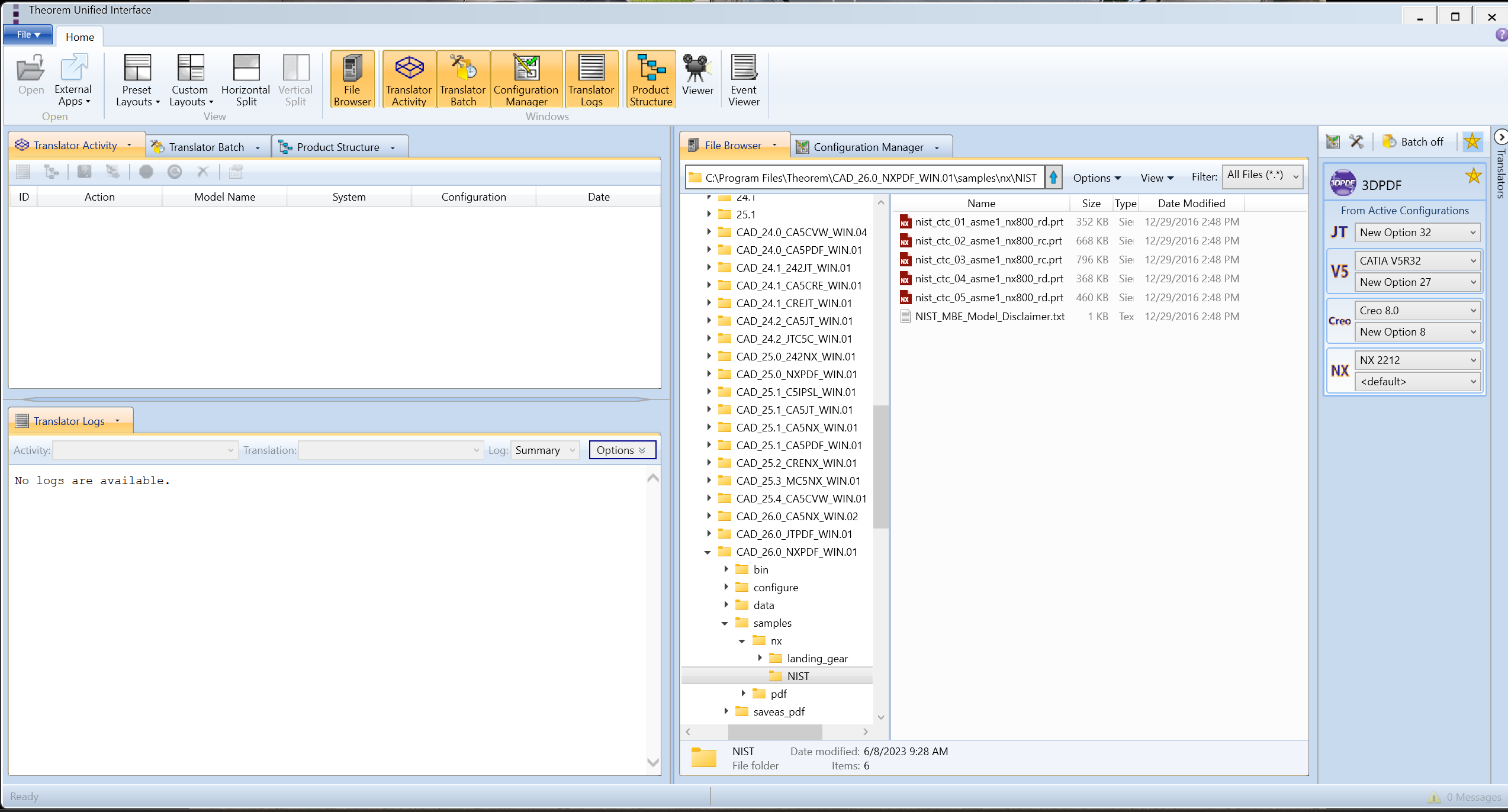
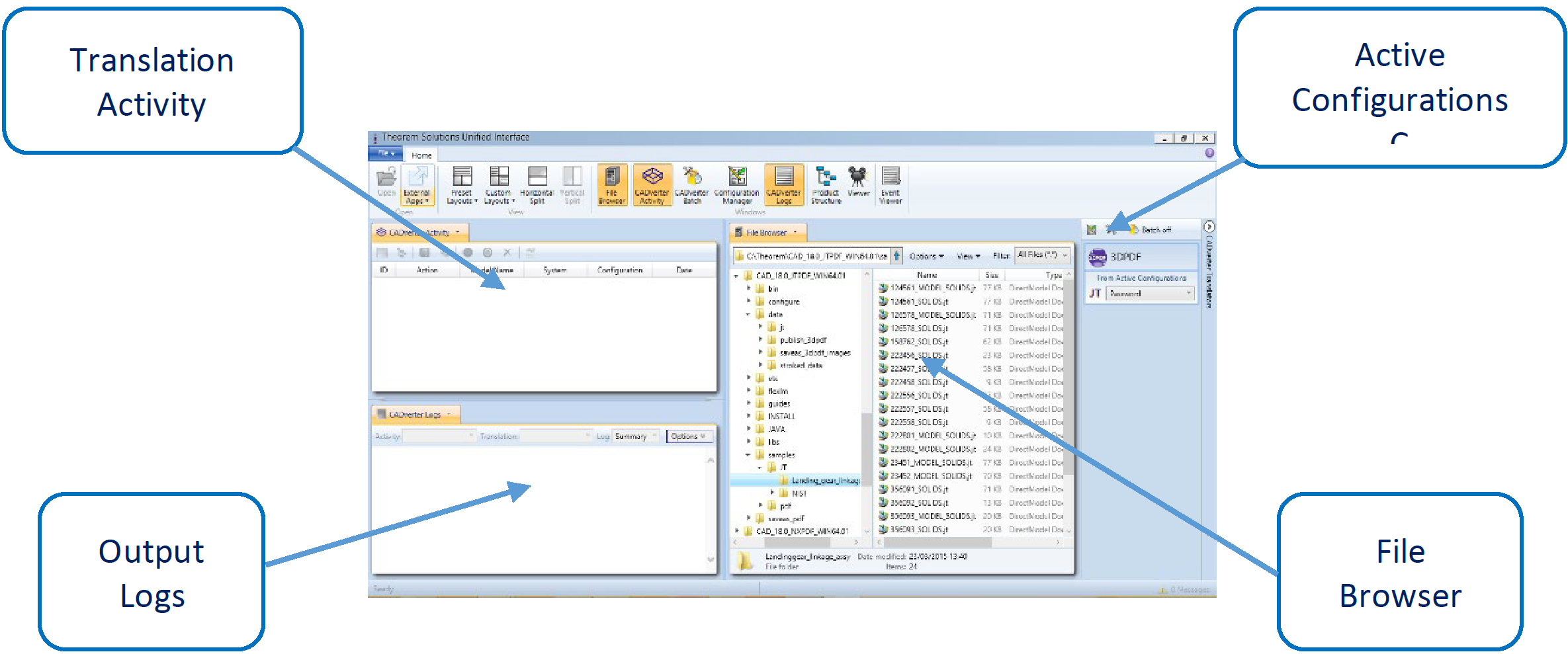
The default layout is split into 4 primary areas, which can be altered to the user’s preference:
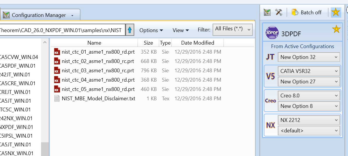
The simplest way to publish a NX file in 3D PDF is to drag a file from the file Browser Pane on to the 3D PDF Active Configuration. This will create a PDF file based upon the default template.
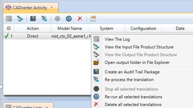
On completion, the Unified Interface will display the activity information and details from the log file created during the translation, if requested, in the Translation Activity and Output Log panes, respectively.
The generated output data can be located by selecting the translation from the Activity pane and opening the output folder:
Default Publishing – via the Command Line
Running a translation via the command line can be carried out via the cad_run.cmd file located in the
<installation_directory>\bin directory. The format of the command is as follows (Note! Replace the [version]
from the example with your version of NX, e.g. NX 2306):
<Translator_installation_directory>\bin\cad_run.cmd NX[version]_3DPDF -I <input_file> -o <output_file>

The example above will translate a sample file provided within the installation and produce the following screen output:
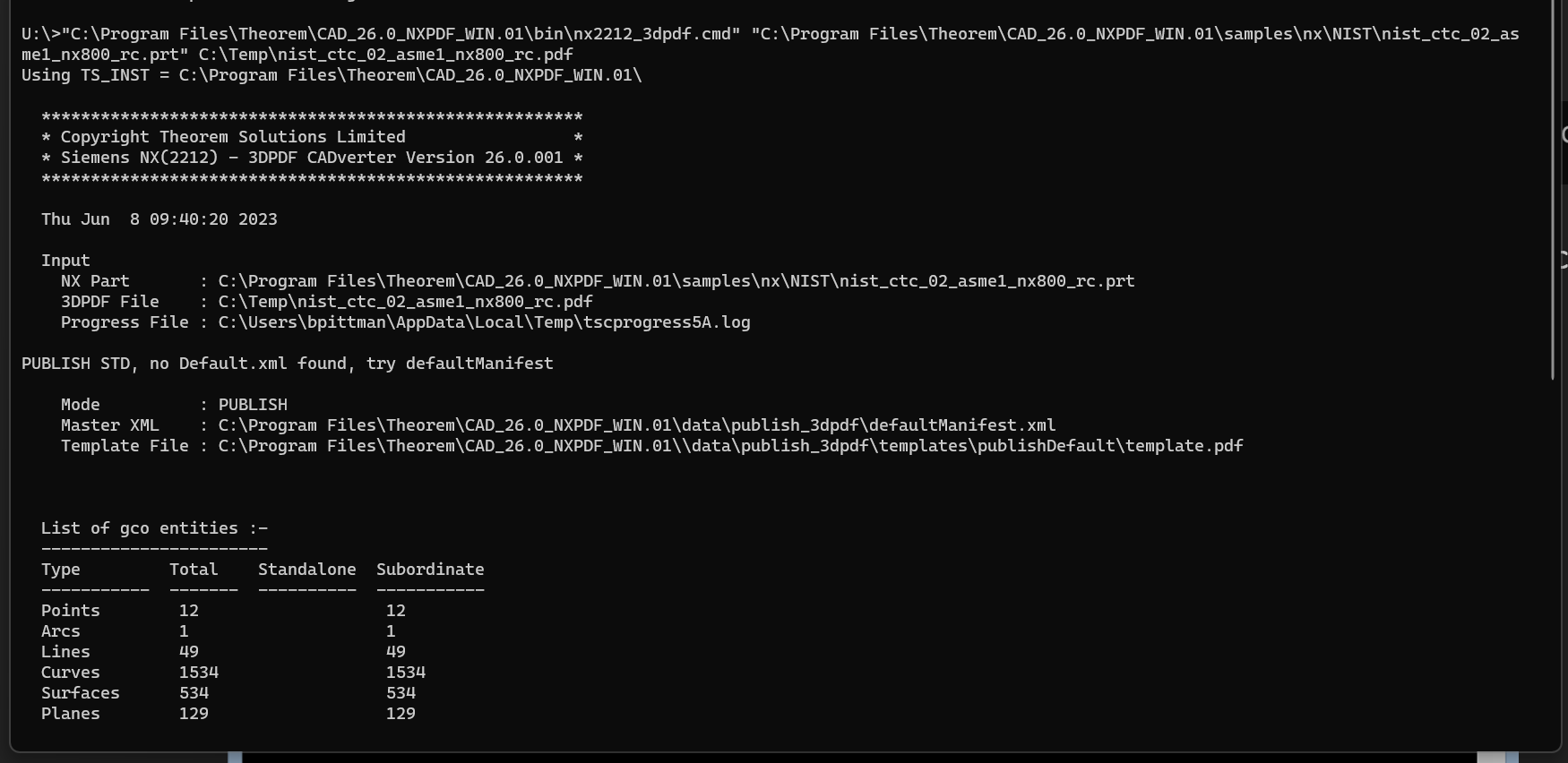
The file will be output to the target location. In this case:
C:\Temp\nist_ctc_02_asme1_nx800_rc.pdf
Publishing to Specific List of Templates
Publishing to Targeted Templates – via the Unified Interface
It is possible to publish to an individual or multiple templates via one translation run using the Unified Interface. In order to do this, a new configuration will be required.
The Configuration Manager pane can be launched via the Active Configuration Pane or from the Ribbon Configuration Manager button:
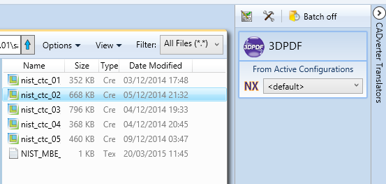
OR

Select the ‘Configuration Manager’ option from the ribbon menu at the top of the Unified Interface. This will then display the ‘Configuration Manager’ pane.
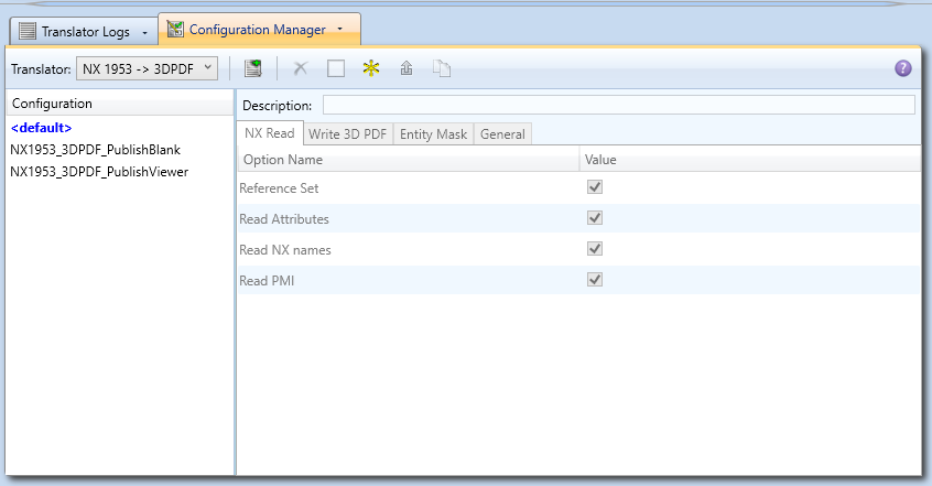
The Configuration Pane allows new configurations to be created based upon ALL available arguments within the Publish 3D application. Selecting the New Configuration icon will allow the user to change any Publish 3D argument.
The panels below show the required selections to create a Configuration to create output based upon Multiple Templates (Note! The same method is used to target an individual template, by selected only one template):
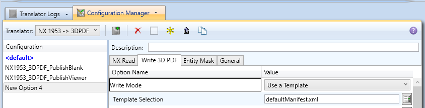
This will open a new selection window. Use the ‘Add File’ button on the right hand side of the window to select your templates.
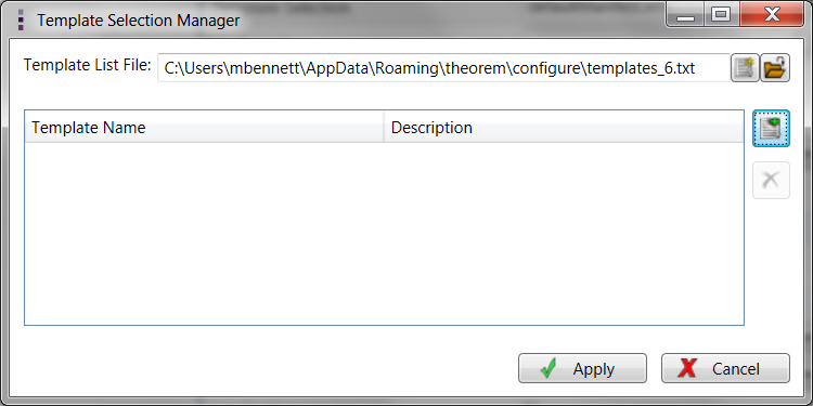
Now select your XML manifest files from the file browser and add them to your selection.
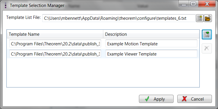
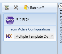
In order to run a translation using this configuration the Active Configuration setting for NX to 3D PDF must be changed to The “Multiple Template Output” Configuration:
Once this has been done the translation can be invoked in the same manner as for the Default publishing mechanism.
Publishing to Targeted Templates – via the Command Line
Publishing to an individual template or multiple templates can also be achieved via the command line interface.
First a list of target Manifest files that describe how to use a template must be created. (Note! For further information regarding our template design services please contact sales@theorem.com quoting “3D PDF Template Design”.)
The list is provided via a text file in the following format:
<Translator_installation_directory>\data\publish_3dpdf\templates\publishViewer.xml<Translator_installation_directory>\data\publish_3dpdf\templates\publishRFQ.xmlNote! Each line points to an XML manifest file, examples of which are provided in the Publish 3D installation.
Once this file has been created the syntax for running a command to publish to multiple templates is as follows (Note! Replace the [version] from the example with your version of NX, e.g. NX1953):
<Translator_installation_directory>\bin\cad_run.cmd NX[version]_3DPDF<input_file> <output_file> publish <manifest list>
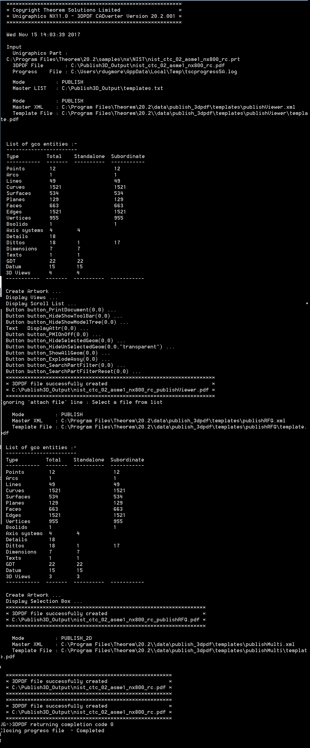
The example above will use the referenced template manifest list and will publish an output to each of the templates referenced via the manifest files provided, whether there be one or many in the list. The following screen output should be expected, producing one “Create Artwork” line per template:
Publishing without a Template
Publishing without a Template – via the Unified Interface
To run Publish 3D without a template in the Unified Interface, navigate to the configuration manager as described, and from the ‘Write Mode’ option in the ‘Write 3D PDF’ tab, select ‘No Template’. Save this configuration as previously described, you are now ready to publish without using a template.
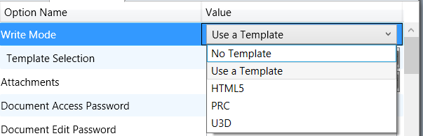
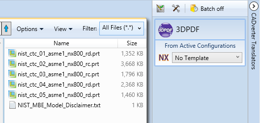
Now, in the ‘Active Configurations’ pane select your configuration from the menu and then ‘drag and drop’ your data to publish it to a PDF document.
On completion, the Unified Interface will display the activity information and details from the log file created during the translation, if requested, in the Translation Activity and Output Log panes, respectively.
The generated output data can be located by selecting the translation from the Activity pane and opening the output folder:
Publishing without a Template – via the Command Line
Publishing without a template can also be achieved via the command line interface.
The syntax for running a command to publish without a template is as follows (Note! Replace the [version] from the example with your version of NX, e.g. NX9):
<Translator_installation_directory>\bin\cad_run.cmd NX[version]_3DPDF<input_file> <output_file> publish off
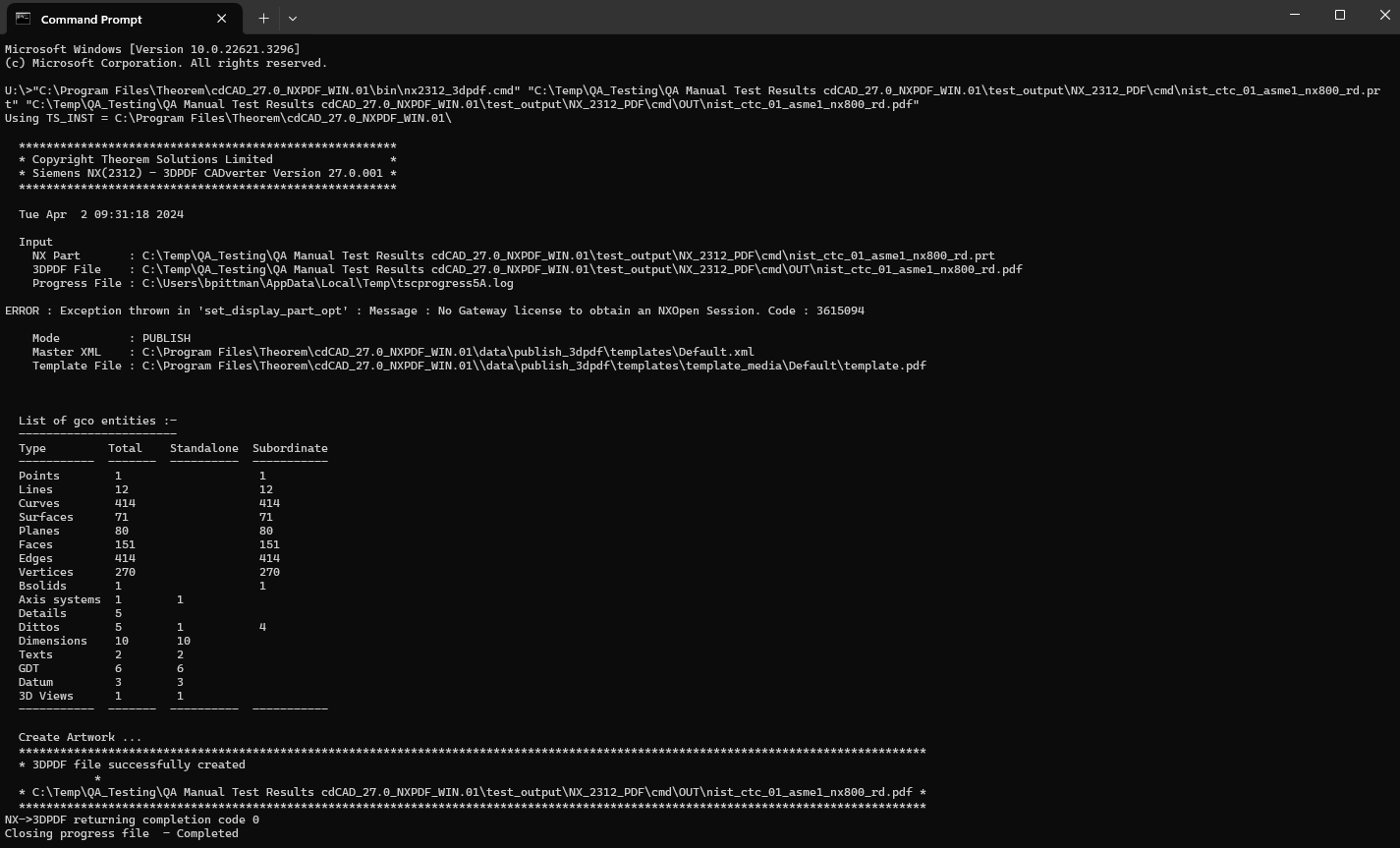
The example above will publish a PDF file containing the model data without any formatting. The following screen output should be expected:
Translator Customization
Publish 3D allows the information that is read from the source system and written to the target system to be tailored via a set of user specified arguments. Commonly used arguments are supported via the Unified Interface, with Advanced Arguments being described within this document for use in the Unified Interface or via the Command Line invocation.
Common Options for NX Publishing
Within the Configuration Manager pane of the Unified Interface, arguments that can be specified when publishing NX data into 3D PDF are grouped into 3 areas:
NX Read – Those arguments that affect how data is read from NX
Write 3D PDF – Those arguments that affect how the data is written to 3D PDF
Entity Masking – Those arguments that allow specific entities to be masked
General – Those arguments that are common to ALL Publishing activities regardless of source data
The image below shows the NX Read arguments that are available, with their default settings:
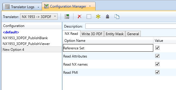
Each of these options is described below:
Option |
Description |
|---|---|
Reference Set |
Enables Reference Set processing. (Default is on). Command Line Syntax:
|
Read Attributes |
Enables NX Attribute processing. (Default is on). Command Line Syntax:
|
Read NX Names |
Read NX Entity Names, if they exist. (Default is on). Command Line Syntax:
|
Read PMI |
Read 3D PMI. (Default is on). Command Line Syntax:
|
The image below shows the Write 3D PDF arguments that are available, with their default settings:
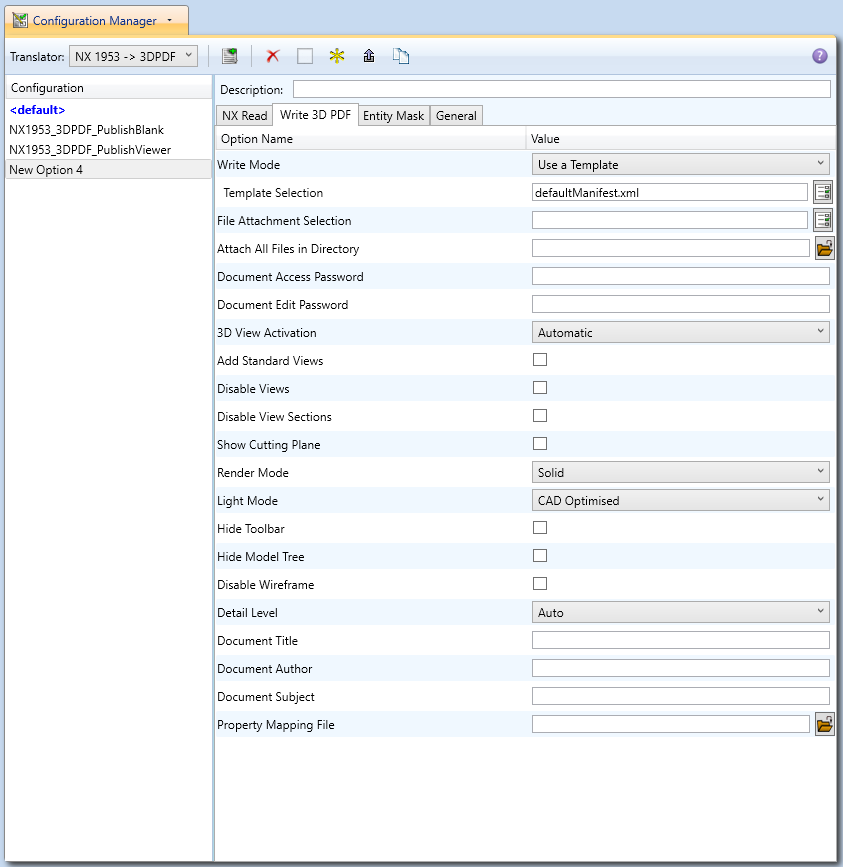
Each of these options is described below:
Option |
Description |
|---|---|
Write Mode |
Contains 5 options:
|
Template Selection |
Select which templates Publish 3D will use to create the output 3D PDF, if Write Mode is set to Use a Template (Default = defaultManifest.xml) Command Line Syntax:
|
File Attachments |
This option allows files to be attached to the output PDF file together with a brief description of the selected files. (Default is for no files to be attached) Command Line Syntax:
Where Attachment_List is a list of full path names to file followed by an optional description line: e.g. C:\TEMP\my_image.jpgThis is a jpg Image
C:\TEMP\report.txtReport Document
C:\TEMP\related.pdfC:\TEMP\another.pdfThis PDF has a description
Note in this example the ‘Related.pdf’ attached file doesn’t have the optional comment. The file path may contain environment variables which will be resolved. e.g. %TEMP%/myFile.pdf |
Attach all files in directory |
Attach the files found in specified directory: Command line syntax:
|
Document Access Password |
If a password is provided in the text field:
Command Line Syntax:
|
Document Edit Password |
If a password is provided in the text field (Note! This password MUST be different from the Document Access Password to enable Document Edit Permissions to be honoured):
Command Line Syntax:
|
3D View Activation |
Specifies how the 3D view in the resultant 3D PDF file is activated (Default is On Selection) Options are:
Command Line Syntax:
|
Add Standard Views |
Add isometric views to the data being written to PDF (Default is off) Command Line Syntax:
|
Disable Views |
Switch off any Captures/Views from being written into the PDF. (Default is off) Command Line Syntax:
|
Disable View Sections |
Switch off any sections within the Captures/Views from being written into the PDF. (Default is off) Command Line Syntax:
|
Show Cutting Plane |
Enable cut plane visulaization. (Default is off) Command Line Syntax:
|
Render Mode |
Controls which Rendering Mode to use for the model. Options are:
Command Line Syntax:
Where mode is set to one of the above values |
Light Mode |
Controls which Light Mode to use. Options are:
Command Line Syntax:
Where mode is set to one of the above values. Note! No command is required for the default value. |
Hide Toolbar |
Hide the 3D Toolbar in the resultant document. This can be re-enabled in Adobe if required. (Default is off) Command Line Syntax:
|
Hide Model Tree |
Hide the Model Tree in the resultant document. This can be re-enabled in Adobe if required. (Default is off) Command Line Syntax:
|
Disable Wireframe |
Disable Wireframe Processing (Default is to Enable Wireframe processing) Command Line Syntax:
|
Detail Level |
The Detail Level option can be used to set the render quality of the resultant 3D PDF output. A number of discrete values are made available via the UI. They correspond to a relative chordal deviation (% of the diagonal length across the model bounding box) or absolute chordal deviation, whichever is the smaller. The following options are available:
For very large (detailed) parts the use of this option (Low or Very Low) can significantly reduce the size of the output PDF file and the time taken to produce it, at the cost of quality. A setting of Medium is seen as a good compromise, between quality and size. This value is the default value. Command Line Syntax:
Where value = ultra_low, v_low, low, med, high, v_high, off |
Document Title |
Set the Document Properties ‘title’ field. Command Line Syntax:
|
Document Author |
Set the Document Properties ‘author’ field Command Line Syntax:
|
Document Subject |
Set the Document Properties ‘subject’ field Command Line Syntax:
|
Property Mapping File |
Allows a user to define how properties can be mapped from NX to the output PDF. Command Line Syntax:
Sample in %Install_dir%\data\publish_3dpdf\attrFilters\defaultAttrFilter.txt |
The image below shows the Masking arguments that are available, with their default settings:
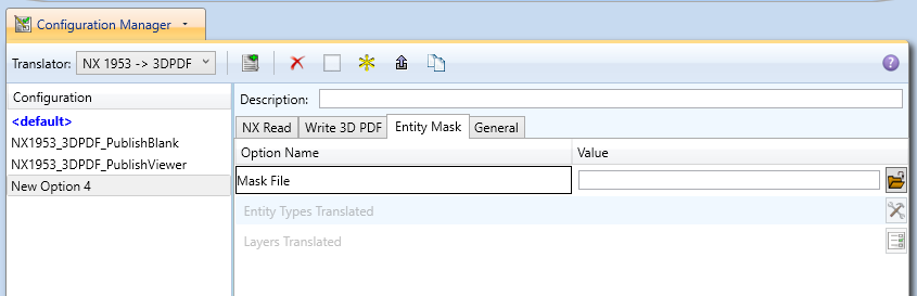
Each of these options is described below:
Option |
Description |
|---|---|
Mask File |
Specifies the Mask File to be written to, that can be referenced by future translations. A Mask file MUST be specified if masking is required. The first line in this file is OFF ALL ENT: Command Line Syntax:
|
Entity Types Translated |
Specifies a selection list from which to select which entity types are to be processed. The following types are available: “POI”,”LIN”,”ARC”,”CON”,”CUR”,”SUR”,”FAC”,”SOL”,”TEX”,”AXI” Command Line Syntax:
|
Layers Translated |
Specifies a selection list from which to select which layers are to be processed. Command Line Syntax:
|
The image below shows the General arguments that are available, with their default settings:
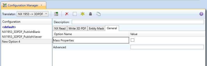
Each of these options is described below:
Option |
Description |
|---|---|
Mass Properties |
Allows Mass Property information to be read from the source data and written as attributes to the PDF document (Default is off) Command Line Syntax:
|
Advanced |
Allows any of the Command Line Advanced arguments documented below to be passed to the Unified Interface invocation |
Command Line Advanced Arguments
Any of the Advanced arguments can be added to the Command Line Invocation or to the General- >Advanced field when run from within the User Interface.
NX Advanced Arguments
Argument |
Description |
|---|---|
|
Read entities from ALL layers even if the layer is invisible |
|
Fits the visible geometry to the screen size (e.g. zooms the view), regardless of users source system settings. The default option is ‘fit_view_as_saved’, which reads the view according to the settings in the source CAD system. |
|
Attempt an NX heal on the (native) body - using the NX API. Note! This should be used in combination with regen_brep |
|
If set, Process As Saved part layers. If unset process All layers |
|
Reads any blanked entities. (Default is off) |
|
Allows assembly component level PMI to be read. (Default is off) |
|
This flag turns on the processing of 3D Views even if ‘read_pmi’ is off. If ‘read_pmi’ is ON, then ‘read_views’ is switched ON automatically. This can be overridden by specifying ‘no_read_views’ If ‘read_pmi’ is OFF, then ‘read_views’ is OFF by default. This can be overridden by specifying ‘read_views’ |
|
If set, append the Reference Set name to created part |
|
Allows brep data to be regenerated from the topology using the NX API. Note! It is only advised to use this option if solid information cannot be written into 3D PDF. |
|
Disables the creation of datum plane borders. The default is to create 4 datum plane bounding lines to mimic NX section lines |
|
Reading of NX assembly arrangements (Default is Off) |
|
Reading of NX face/body translucency (Default is Off) |
|
Using this additional option ensures that only the views that have the attribute “publish for disclosure” flag set to “True” are processed from the input file to the output PDF |
|
Reads all of the NX standard views |
|
Using this option allows you to retain trimmed bodies on the sectioned side of a section view. |
3DPDF Advanced Arguments
Argument |
Description |
|---|---|
|
Specify the log file for this process. |
|
Add ‘info’ messages to the log file. |
|
Switch off the writing of instance colours. |
|
Switch off the writing of any colours. |
|
Switch off the writing of attributes into the PDF. |
|
Disables edge highlighting |
|
By default a 2D poster is generated from the 3D model which can
be very time consuming for a complex model. This option disables
that process and uses a default JPG called
|
|
Where r g b are values 1 to 255, this controls the background colour of the 3D display, which now defaults to pale grey (204,204,204). |
|
Where r g b are values 1 to 255, this controls the override PMI colour. By default PMI is displayed in the same colour as the source CAD system. When a colour is not read the default will be black. This option allows the PMI colour to be fixed to any colour, clearly this is a single override colour for all PMI. |
|
Where r g b are values 1 to 255, this controls the override PMI colour. By default wireframe is displayed in the same colour(s) as the source CAD system. This option allows the wireframe colour to be fixed to any colour, clearly this is a single override colour for all PMI. |
|
Where value = tess_low,tess_med,tess_high, nurb or off When this option is selected the wireframe entities are written as lines/conic/nurbs. This results in a wire node for each entity contained under the Wireframe node in the model tree, there could be many wire nodes in a complex model. If any of the settings prefixed tess are used, these options convert wireframe into a number of sampled points on the curve and writes wireframe as a Poly Line, this allows many wires to be combined. However a Poly Line can only be a single colour, so wireframe of the same colour will be grouped into a Poly Wire, which will be a wire node contained under the Wireframe node in the model tree, there will be a wire node for each colour, when multi colours exist. If however all wireframe is the same colour, all wireframe is contained in the Wireframe node. |
|
This is a method to define which attributes are masked or included during translation. By default there is an attribute filter file installed at:
This command line option allows this file to be overridden, such that the named file is used instead of the default. The file format is best explained by means of examples: MPARTNAME,,0,,, (Delete MPARTNAME attribute)FILENAME,F I L E (name),1,,, (Rename ‘FILENAME’ to ‘F I L E (name)’)FILESIZE,,3,big,, (Default (always) FILESIZE value to big)*END,,0,,, (Delete all attributes that end with ‘END’)Theorem*,,0,,, (Delete all attributes that start with ‘Theorem’) |
|
This is a utility which can be used to generate a text file with the Key/Value pairs from the GCO DESIGN,DITTO and DETAIL entities, this can be used in the ‘design’ of templates. |
|
When assembly nodes contain no geometry, (could be due to missing part files) this option results in the model tree with ‘un- ticked’ nodes where no geometry was read. Where the 3DGeom node would be there will be a NoGeom node. Please note in order to activate this behaviour it was necessary to add a point at 0,0,0 which is contained by the NoGeom node. |
|
Where value = v_low, low,med,high,v_high,off These options can be used to control the tessellation setting, using the values 10,25,50,75,90%. These compression settings apply ONLY to PRC/U3D output files. |
|
Force views to be first angle projection regardless of source data |
|
Force views to be third angle projection regardless of source data |
|
Attributes on parts can be copied onto instance nodes with this option (default is off). (The user can enable dump_attr_file <file> option to confirm what attributes are available on part/instances, to check the effect of this option) |
|
Disable section capping (Default is on) |
|
When section cutting planes are enabled, the cutting plane colour can be controlled by r g b values in the range of 1 to 255 |
|
When section cutting planes are enabled, the cutting plane opacity can be specified by setting ‘val’ between 0.0 and 1.0 |
|
Section cutting intersections can be enabled via this option. (Default is off) |
|
When section cutting plane intersections are enabled, the cutting plane intersection colour can be controlled by r g b values in the range of 1 to 255 |
|
By default BREP data is omitted when the PDF file is generated so this options allows for such data to be retain. Do not use this option when the generation of BREP data in PDF is forbidden for legal or commercial reasons. |
|
There are occasions when the source data presented for
publishing to 3D PDF is invalid. In these circumstances, a
validation of the data is carried out by the translator and the user
is advised, via a message to the screen to re-run the translator,
specifying the |
|
By default this option is on. It will detect instances with no names and apply the part name to those instances. This accommodates cases where instance names are not available in the source data. |
|
This option will automatically display the resulting PDF file in an
Adobe Reader. The environment variable |
|
This can be useful when data is created with many open solids (1 per face). This can result in many 100’s or even 1000’s of solids which causes the 3D PDF file to have a massive entity tree, to be slower and larger than necessary, and with a Bounding Box for each face. Setting this option groups the solids into logical entities. |
|
Some systems will group solids by default so this option allows that setting to be disabled. |
|
Wireframe entities that are marked as invisible are by default NOT processed. This option allows them to be processed. |
|
By default extra checks are made to prevent views with clipped geometry. This flag disables these checks. |
|
This option is used to limit the number of PMI to Geometry associations that exist for any single PMI node. The default value being 500. It has been found that in rare cases many 1000’s of associations exist and this has a significant effect on the translation time. If the limit is exceeded the log file reports the PMI entities names and reports an error, allowing the user to modify the limit, or review the PMI’s validity. |
|
Set the permissions for the PDF file, the options being “PRINT” or “LOCK”, if no options are set then the create PDF file is fully open, the “PRINT” setting allows the file ONLY to be printed, the “LOCK” setting ensure the document cannot be modified. (Be aware that with Adobe Writer it is possible to override any permission setting). |
|
This allows the full control of all the permission settings when creating a PDF file, the in values need to be logically ORed together so 0x2 and 0x1 become 3. values are 0xHex (decimal) 0x01 (1) - DocumentPermOpen The user can open and decrypt the document. 0x02 (2) - DocumentPermSecure The user can change the document’s security settings. 0x04 (4) - DocumentPermPrint The user can print the document. Page Setup access is unaffected by this permission, since that affects Acrobat’s preferences - not the document’s. In the Document Security dialog, this corresponds to the Printing entry. 0x08 (8) - DocumentPermEdit The user can edit the document more than adding or modifying text notes (see also DocumentPermEditNotes). In the Document Security dialog, this corresponds to the Changing the Document entry. 0x10 (16) - DocumentPermCopy The user can copy information from the document to the clipboard. In the document restrictions, this corresponds to the Content Copying or Extraction entry. 0x20 (32) - DocumentPermEditNotes The user can add, modify, and delete text notes (see also DocumentPermEdit). In the document restrictions, this corresponds to the Authoring Comments and Form Fields entry. 0x40 (64) - DocumentPermSaveAs The user can perform a Save As…. If both DocumentPermEdit and DocumentPermEditNotes are disallowed, Save will be disabled but Save As… will be enabled. The Save As… menu item is not necessarily disabled even if the user is not permitted to perform a Save As… 0x100 (256) - DocumentPermFillandSign Overrides other DocumentPerm bits. It allows the user to fill in or sign existing form or signature fields. 0x200 (512) - DocumentPermAccessible Overrides DocumentPermCopy to enable the Accessibility API. If a document is saved in Rev2 format (Acrobat 4.0 compatible), only the DocumentPermCopy bit is checked to determine the Accessibility API state. 0x400 (1024) - DocumentPermDocAssembly Overrides various DocumentPermEdit bits and allows the following operations: page insert/delete/rotate and create bookmark and thumbnail. 0x800 (2048) - DocumentPermHighPrint This bit is a supplement to DocumentPermPrint. If it is clear (disabled) only low quality printing (Print As Image) is allowed. On UNIX platforms where Print As Image doesn’t exist, printing is disabled. 0x8000 (32768) - DocumentPermOwner The user is permitted to perform all operations, regardless of the permissions specified by the document. Unless this permission is set, the document’s permissions will be reset to those in the document after a full save. 0x10000 (65536) - DocumentPermFormSubmit This should be set if the user can submit forms outside of the browser. This bit is a supplement to DocumentPermFillandSign. 0x20000 (131072) - DocumentPermFormSpawnTempl This should be set if the user can spawn template pages. This bit will allow page template spawning even if DocumentPermEdit and DocumentPermEditNotes are clear. 0xFFFFFFFF - All permissions. |
|
This option creates a pseudo assembly structure below a part, such that each solid is modelled by a separate node. The default is to combine all solids that belong to the same part. Using this option can be useful when control over part with multiple solids is required, e.g. view/hide separate solids, however it should be noted that this option may compromise other functionality, such a PMI association. |
|
This option will magnify the view by the value provided, this is defaulted to 2.0 for all CAD systems. Values < 1.0 zoom out and values > 1.0 zoom in. The purpose of this option is to expose an adjustment factor that a given CAD system might need to best fit the VIEWS in PDF, this may be affected by the aspect ratio of the page size/template used in PDF write. Every effort has been made to set a good value by default. |
|
When ‘on’ the 3DGeom node names are replaced by the TAG name from the detail (part name). Default is off. |
|
This option enables the processing of flat to screen PMI data, the default is off. Please note fonts are not currently supported ‘on’ allows for FLAT TO TEXT types to be processed ‘all’ allows all FLAT TO SCREEN types to be process, however only the text and NOT the frames are processed |
|
Attach ALL file found in specified directory |
|
Option to append the attributes in PDF with useful data, like part count, which can be consumed by the templates. default - just add part count <file> - add the part count and process the file, such that 3 lines are processed part_name // matches the detail (part name)
attr_name // name of attribute to be added
attr_value // value of the attribute to be added
|
|
Move the sub assy PMI to top level. “all” will reposition all PMI into global space which can be used for true assemblies |
|
Processing by default is optimised for facet only data. If some data is incorrectly published this option can be used to check the facet quality. |
|
Expand the structure for a node per point using the tag name |
|
Import images into a template from a directory. |
Publish 3D Interactive
Publish 3D Interactive allows an active NX Part or Assembly to be published directly into 3D PDF, directly from the NX application.
In order to publish from within NX, the NX application must be started from within a Theorem environment, so that the appropriate NX menus are loaded.
NX can be started from a shortcut, if requested at installation time. Alternatively, it can be started via the script provided in the Publish 3D installation at:
<installation_directory>\bin\RunNX[version].cmd
(where [version] should be substituted for the version of NX that you have installed – e.g., 2212 2306 2312):
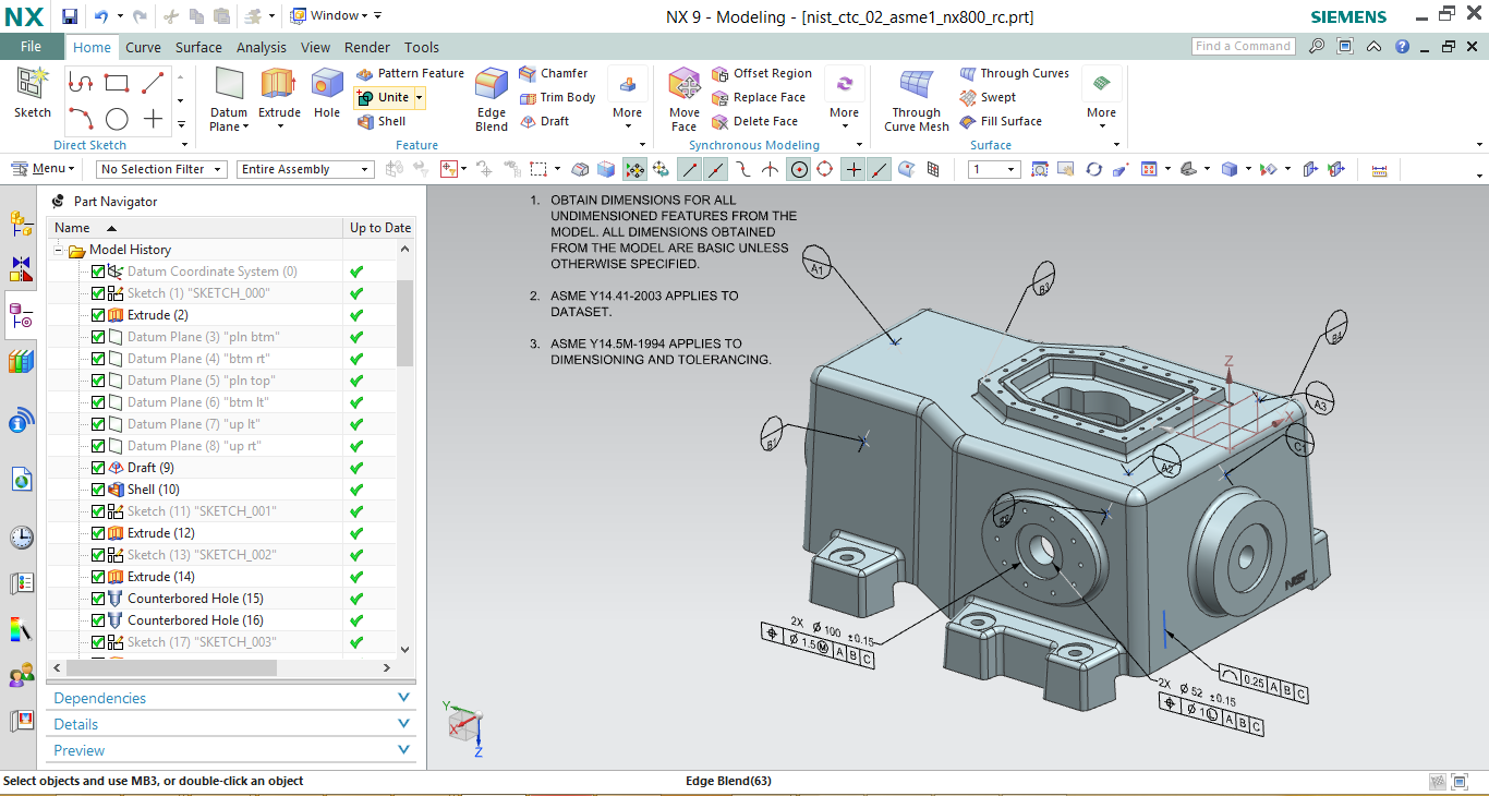
Once NX has been started and a model loaded, the active Part or Assembly can be exported by selecting the File->Export->Theorem Publish 3D Interactive menu:
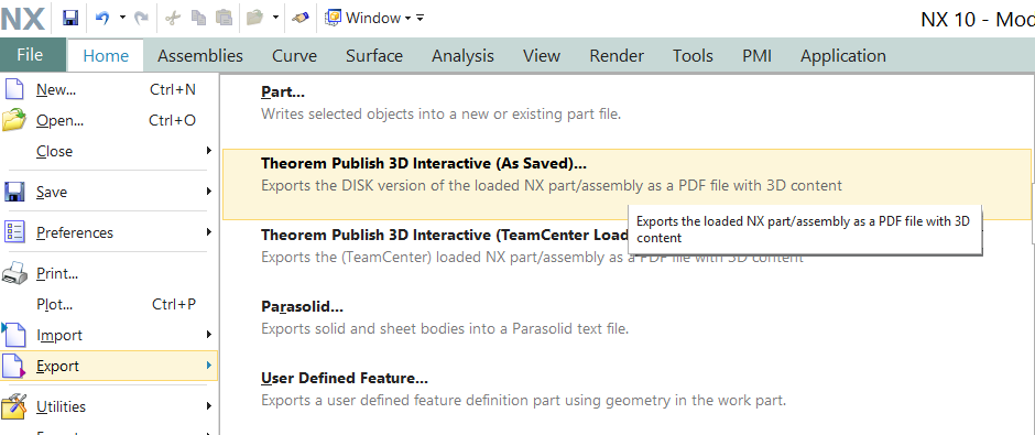
This will present the user with 2 options. If the user is using geometry loaded from the file system, then they should select (As Saved). If the models have been loaded from a TeamCenter environment then (TeamCenter Loaded) must be selected.
Having selected to export to 3D PDF the following menu will be presented to the user:
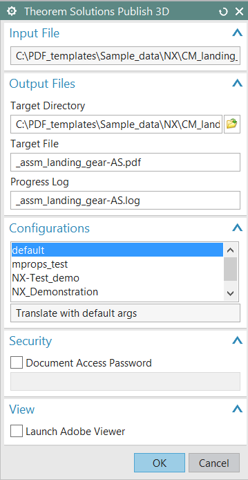
The Publish 3D Interactive interface allows the user to specify:
A target output directory
A target file name
A target log file (Progress File)
A predefined configuration files, used to set translation options and populate a predefined template
If you would like more information regarding our template design services please contact sales@theorem.com quoting “3D PDF Template Design”.
A password for the document – if required
The capability to launch the PDF on completion
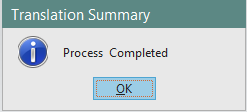
On selecting ‘OK’ a command window will be launched to display the translation process. On completion a dialog will be displayed to inform the user of the translation success/failure:
Setting your own NX Custom Dirs file
If you use your own custom_dirs.dat file with your NX installation and want to integrate Theorem menus you will need to complete the following actions:
Run “Configure.cmd” found in your Theorem software \bin directory.
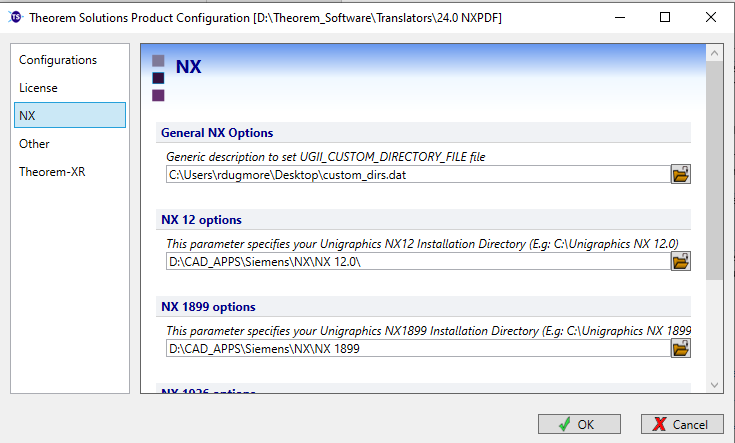
In the “General NX Options” section, select the custom_dirs.dat file that you wish to use with Theorem software.
You will then need to open your custom_dirst.dat file in a text editor and add in the following line:
${TS_INST}/ugmenus/v${NX_COMPATIBLE_BASE_RELEASE_VERSION}/ug_customisations
Once complete and you launch NX from your launcher, Theorem menus will be present to use.
Options for Processing FTA Data with Filled Text
Configuration Manager
The configurations listed under the Theorem Options panel are managed using the Configuration Manager from the Unified Interface for Publish 3D On Demand users (See ‘Configuration Manager’ on Page 12).
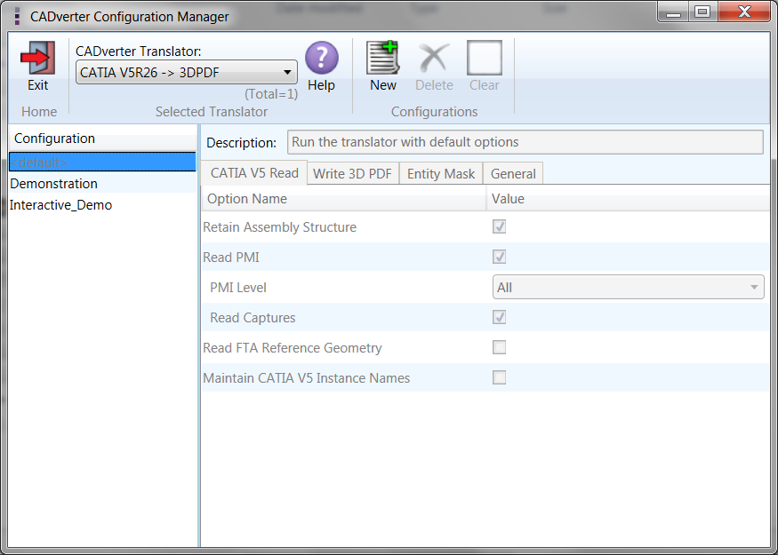
For Publish 3D Interactive only users, the configurations are managed using a standalone Configuration Manager. The configuration manager is launched by running the ConfigurationManager.cmd file from the \bin directory of your Theorem installation. The Configuration Manager (displayed below) is used to create configurations that can define things such as which options are used to publish files to 3DPDF and what template is used. These can then be saved and selected as part of your publishing process.
Security Changes to Adobe Reader
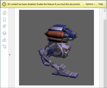
Adobe have implemented new security options to disable the autoplay of 3D content in PDF files. The following banner will be displayed upon opening a PDF file that contains 3D content:
To enable 3D content in the current document:
Click the Options button and then select an appropriate option:
Trust this document one time only
Trust this document always
To enable 3D content permanently in ALL documents:
Go to Edit > Preferences > 3D & Multimedia and then select the Enable playing 3D content checkbox