User Guide
Using the Product
Default Translations
Default Translation – via the Unified Interface
The Unified Interface can be started via the Start Menu – if a shortcut was added during installation.
Alternatively, the Unified Interface can be run via a Windows Explorer selection in:
<UI_installation_directory>\bin\Unified_Interface.cmd
The following interface will be launched:
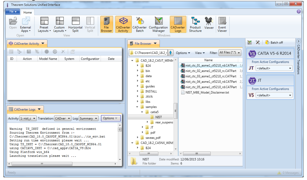
The default layout is split into 4 primary areas, which can be altered to the users preference. The simplest way to translate from CATIA V5 or JT is to drag a file from the file Browser Pane on to the Active Configurations for the translation you require.
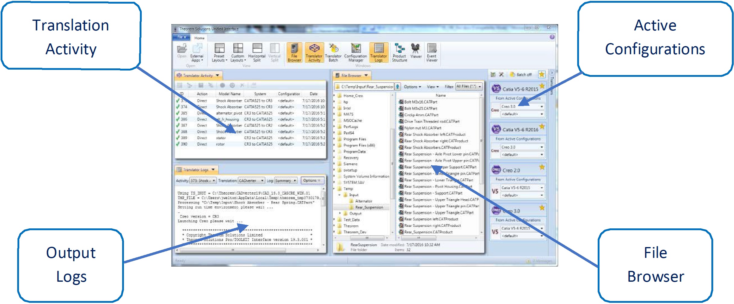
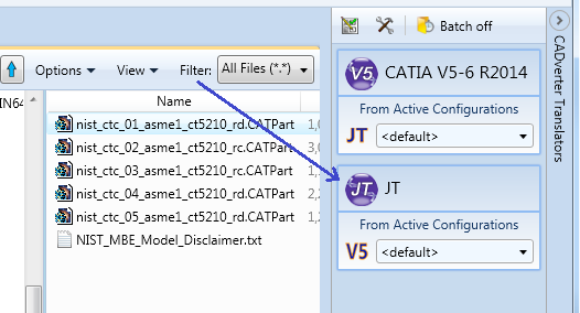
On completion, the Unified Interface will display the activity information and details from the log file created during the translation, if requested, in the Translation Activity and Output Log panes, respectively.
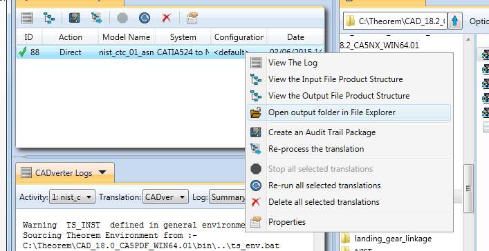
The generated output data can be located by selecting the translation from the Activity pane and opening the output folder.
Default Translation – via the Command Line
Running a translation via the command line can be carried out via the cad_run.cmd file located in
the <installation_directory>\bin directory. The format of the command is as follows when
translating from CATIA V5 to JT:
<Translator_installation_directory>\bin\cad_run.cmd CATIA5[XX]_JT -i <input_file> -o <output_file>
The format of the command is as follows when translating from JT to CATIA V5:
<Translator_installation_directory>\bin\cad_run.cmd JT_CATIA5[XX] -i <input_file> -o <output_file>
(Note! Replace the [XX] seen in the example with the version of CATIA V5 you are using. E.g. for CATIA V5 R34 (V5-6 R2024), change to CATIA534.)

The example above will translate a CATIA V5 sample file provided within the installation and finish with the following screen output when successful:
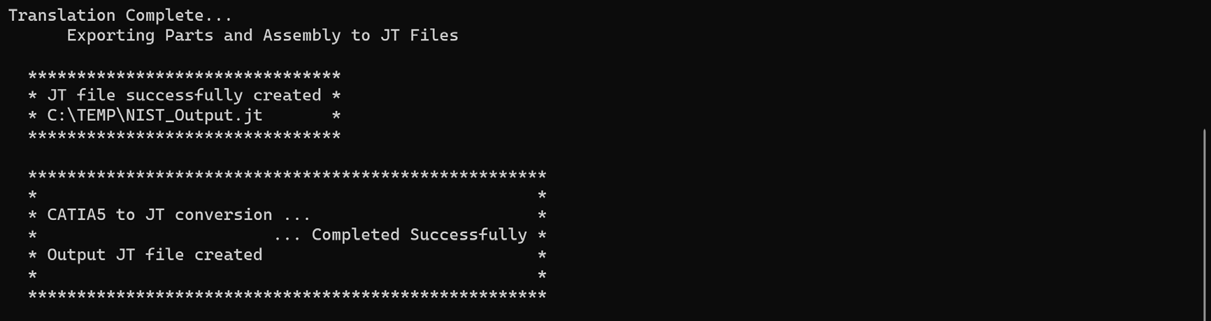
The file will be output to the target location. In this case:
C:\Temp\NIST_Output.jt
Translator Customization
SpinFire Convert allows the information that is read from the source system and written to the target system to be tailored via a set of user specified arguments. Commonly used arguments are supported via the Unified Interface, with Advanced Arguments being described within this document for use in the Unified Interface or via the Command Line invocation.
Common Options for CATIA V5 to JT
Within the Configuration Manager pane of the Unified Interface, arguments that can be specified when publishing CATIA V5 data into JT are grouped into 4 areas:
CATIA V5 Read – Those arguments that affect how data is read from CATIA V5
JT Write – Those arguments that affect how the data is written to JT
Entity Mask – Those arguments that allow specific read entities to be masked
General – Those arguments that are common to ALL Publishing activities regardless of source data.
CATIA V5 Read Arguments
The image below shows the CATIA V5 Read arguments that are available, with their default settings:
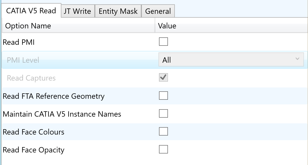
Each of these options is described below:
Option |
Description |
|---|---|
Read PMI |
Enables PMI data read from the V5 file. (Default is ON). Command Line Syntax:
Note: When ‘read_pmi’ is enabled it also enables the ‘fill_pmi_arrows’, ‘fill_pmi_text’ and ‘pmi_filled_text’ options. These can be overridden by setting the Advanced arguments: ‘dont_fill_pmi_arrows’ and/or ‘dont_fill_pmi_text’ |
PMI Level |
A secondary argument to ‘Read PMI’ and allows control of the level of PMI to be read. Default is ALL when ‘Read PMI’ is marked as ON. Options Available:
|
Read Captures |
A secondary argument to ‘Read PMI’ and allows the control over whether captures are read as part of the process. Default is ON when ‘Read PMI’ is marked as ON. Command Line Syntax:
|
Read FTA Reference Geometry |
Enables reading of FTA Reference Geometry (Default is Off) Command Line Syntax:
|
Maintain CATIA V5 Instance Names |
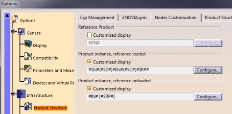
Honours CATIA V5 Tools->Options->Infrastructure->Product Structure->Nodes Customization panel settings (Default is Off) Command Line Syntax:
|
Read Face Colours |
Read the face colours (Default is OFF) Command Line Syntax:
|
Read Face Opacity |
Read the opacity of the face (Default is OFF) Command Line Syntax:
|
JT Write Arguments
The image below shows the Write JT arguments that are available, with their default settings:
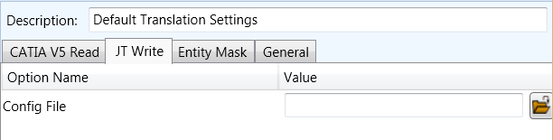
Each of these options is described below:
Option |
Description |
|---|---|
Config File |
Allows a JT configuration file to be specified. Please see JT Configuration File for a full description of the JT config file format. Command Line Syntax:
|
CATIA V5 to JT Entity Masking Arguments
The image below shows the Masking arguments that are available, with their default settings:
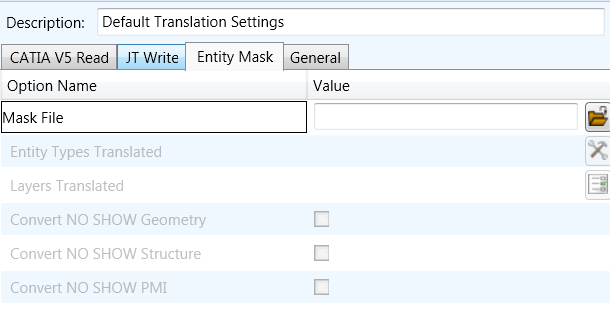
Each of these options is described below:
Option |
Description |
|---|---|
Mask File |
Specifies the Mask File to be written to, that can be referenced by future translations. A Mask file MUST be specified if masking is required. The first line in this file is OFF ALL ENT. Command Line Syntax:
|
Entity Types Translated |
Specifies a selection list from which to select which entity types are to be processed. The following types are available: “POI”,”CUR”,”SKI”,”SOL”,”ISO”,”TEX”,”AXI” Command Line Syntax:
|
Layers Translated |
Specifies a selection list from which to select which layers are to be processed. Command Line Syntax:
|
Convert NO SHOW Geometry |
Enables Hidden geometry to be processed (Default is Off) Command Line Syntax:
|
Convert NO SHOW Structure |
Enables Hidden Assembly Structure to be processed (Default is Off) Command Line Syntax:
|
Convert NO SHOW PMI |
Enables Hidden PMI to be processed (Default is Off) Command Line Syntax:
|
CATIA V5 to JT General Arguments
The image below shows the General arguments that are available, with their default settings.
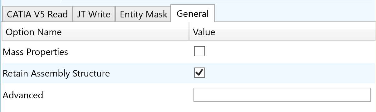
Each of these options is described below:
Option |
Description |
|---|---|
Mass Properties |
Allows Mass Property information to be read from the source data and written as attributes (Default is OFF) Command Line Syntax:
|
Retain Assembly Structure |
Maintain the assembly structure during translation. (Default is ON) Command Line Syntax:
|
Advanced |
Allows any of the Command Line Advanced arguments documented to be passed to the Unified Interface invocation. |
Processing CATIA V5 FTA data to JT PMI
When using the optional CATIA V5 to JT PMI add-on module all CATIA V5 FTA data can be translated to JT PMI output. This includes the translation of 3D dimensions and annotations which are mapped to the equivalent JT PMI entities. In addition, CATIA V5 3D sections are also able to be translated. The CATIA V5 Capture definitions, which manage the visibility of selective FTA elements as well as the view zoom and orientation, are directly mapped to JT Model Views.
Options for Processing FTA Data with Filled Text
When creating 3D dimensions and annotations with the CATIA V5 FTA module the user can create the text using either stick or filled text fonts. By default, the processing of CATIA V5 filled fonts will recreate the JT output using JT text glyphs. One benefit of using JT glyph-based text definitions is that when the model is reoriented, such that the initial view of the text is reversed, the user can select the annotations to be automatically reoriented. If the filled font representation was created with a simple polygon fill only the character outline would be reoriented and the polygon fill would remain in its original location making the output unreadable.
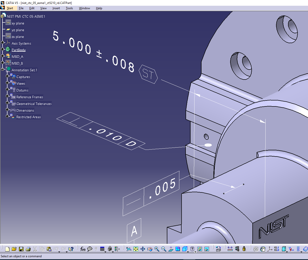
Picture showing typical CATIA V5 3D Dimensions and Annotations. Note, in the upper dimension the dimensions values 5.000 +- .008 are created using a filled text font. The characters “ST” in the frame are created using an unfilled stick font.
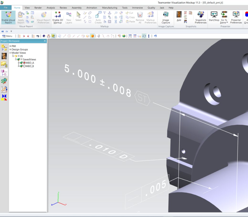
Picture showing default JT output of V5 FTA data mapped to JT PMI representation.
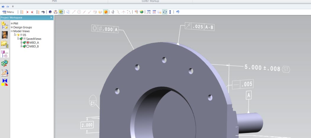
Picture showing the reorientation of the model with the text also reoriented. Note the text characters have been rotated 180 degrees and are now readable with filled character representation.
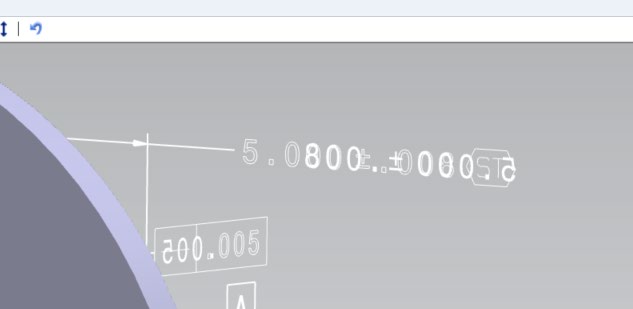
To recreate the JT filled text using simple polygons, rather than JT text glyph representations, use
the options pmi_glyphs_off pmi_polygons together. The output representation will appear filled
and look correct when viewed in the authored orientation. However, filled text created with
simple polygons, will not display correctly if the data is reoriented and the text switching in JT is
selected. The picture below shows an example of the display when the data is rotated, and the
text is reoriented. As you will see the simple polygon fill is still in its original orientation making
the dimension unreadable.
Options for Processing FTA Data using Outline Text
When processing V5 FTA text data created with filled font definition the user can select to
generate the JT text representation as outline text, therefore removing the internal rendering.
This is achieved by using the option pmi_glyphs_off.
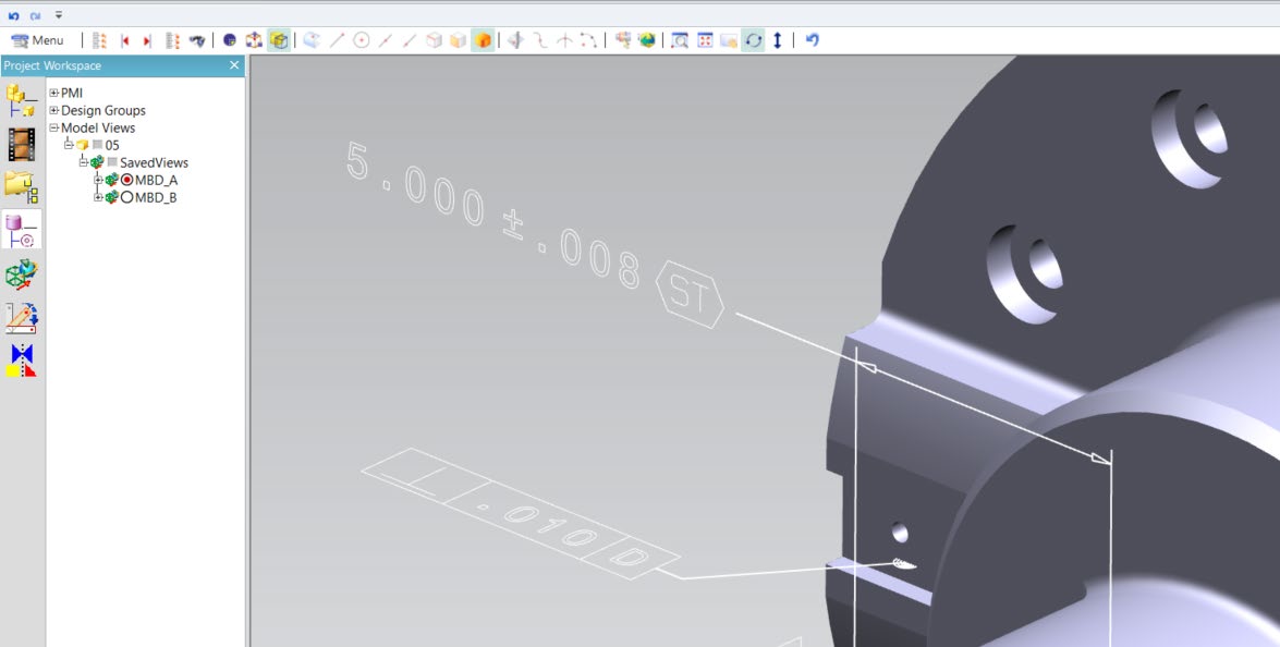
Picture showing JT PMI with filled text rendered in outline only. Note the option pmi_glyphs_off
also removes the filled arrowhead rendering.
If you would prefer to maintain filled arrowheads and only impact the characters to be recreated
in outline mode, then use the option dont_fill_pmi_text instead of the option pmi_glyphs_off.
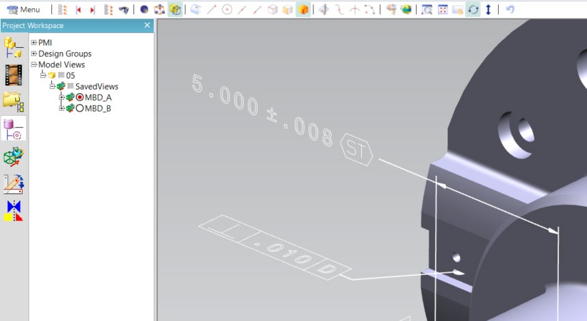
The resultant output is shown in the picture above with the text drawn in outline and the arrowheads filled.
Common Options for JT to CATIA V5
Within the Configuration Manager pane of the Unified Interface, arguments that can be specified when publishing JT data into CATIA V5 are grouped into 3 areas:
JT Read – Those arguments that affect how data is read from JT
CATIA V5 Write – Those arguments that affect how the data is written to CATIA V5
General – Those arguments that are common to ALL Publishing activities regardless of source data
JT Read Arguments
The image below shows the JT Read arguments that are available, with their default settings:
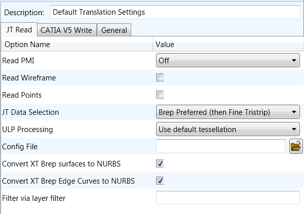
Each of these options is described below:
Option |
Description |
|---|---|
Read PMI |
Reads 3D PMI. Default is OFF. Command Line Syntax:
|
Read Wireframe |
Read JT wireframe data. Default is OFF. Command Line Syntax:
|
Read Points |
Read JT point data. Default is OFF. Command Line Syntax:
|
JT Data Selection |
Select Brep or tessellated data read. Default is ‘Brep Preferred (then fine facet)’. Command Line Syntax:
|
ULP Processing |
How to process ULP data in the JT part. Default is ‘Use Default Tessellation’. Command Line Syntax:
|
Config File |
Config File for Brep or ULP tessellation. Command Line Syntax:
|
Convert XT Brep surfaces to NURBS |
Read XT Brep surfaces as NURBS surfaces (else read in native form). Default is ON. Command Line Syntax:
|
Convert XT Brep Edge Curves to NURBS |
Read XT Brep edge curves as NURBS curves (else read in native form). Default is ON. Command Line Syntax:
|
Filter via layer filter |
Supply layer filter(s) separated by commas and double quoted. Default is OFF. Command Line Syntax:
|
CATIA V5 Write Arguments
The image below shows the CATIA V5 Write arguments that are available, with their default settings:
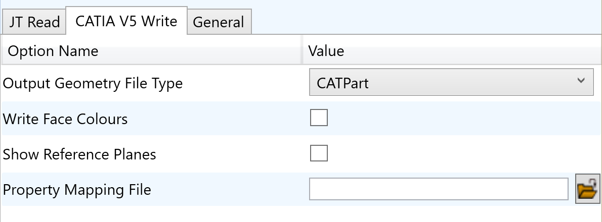
Each of these options is described below:
Option |
Description |
|---|---|
Output Geometry File Type |
Output Geometry file type. Default is CATPart. Command Line Syntax:
|
Write Face Colours |
Writes face colours. Default is ON. Command Line Syntax:
|
Show Reference Planes |
Creates reference planes. Default is OFF. Command Line Syntax:
|
Property Mapping File |
Path to Property Mapping File Command Line Syntax:
|
JT to CATIA V5 General Arguments
The image below shows the General arguments that are available, with their default settings:
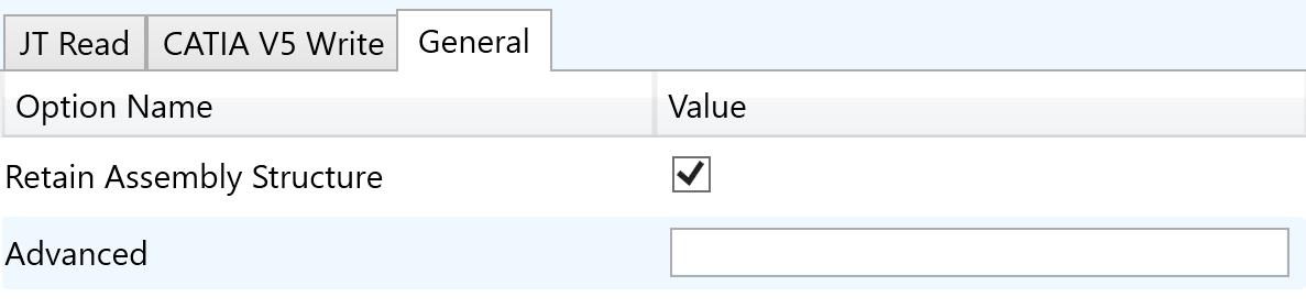
The option is described below:
Option |
Description |
|---|---|
Retain Assembly Structure |
Maintain the assembly structure during translation. (Default is ON) Command Line Syntax:
|
Advanced |
Allows any of the Command Line Advanced arguments documented below to be passed to the Unified Interface invocation. |
Command Line Advanced Arguments
Advanced arguments can be added to the Command Line or the UI General->Advanced field.
CATIA V5 Advanced Arguments
Argument |
Description |
|---|---|
|
Converts curves to NURBS form |
|
Converts surfaces to NURBS form |
|
Disables the read of filled arrow information |
|
Disables the read of filled text information |
|
Disables the read of PMI Capture information |
|
Read face opacity |
|
Sets the default to SOLID colours |
|
Reads hidden geometry / structure / pmi |
|
Allows sub-part specification tree information to be read and presented to JT as product structure information. |
|
CATIA V5 allows the display of shaded surfaces and edges. This option allows the translator to mimic this for FTA construction geometry by promoting the edge curves to standalone wireframe. |
|
Creates a cad property mapping file containing all attributes if one doesn’t exist. |
|
Removes all assembly structure and collapses ALL geometry into a single selectable object |
JT Advanced Arguments
Argument |
Description |
|---|---|
|
Enables reading of Wire Frame entities |
|
Reads reference planes |
Translating Interactively from within CATIA V5
The CATIA V5 to JT translator allows an active CATIA V5 Part or Assembly to be translated directly into JT or a JT Part or assembly to be imported, directly from the CATIA V5 application.
In order to translate from within CATIA V5, the CATIA V5 application must be started from within a SpinFire Convert environment, so that the appropriate CATIA V5 menus are loaded.
CATIA V5 can be started from a shortcut, if requested at installation time. Alternatively, it can be started via the script provided in the Translator installation at:
<installation_directory>\bin\catia5r[version]_start.cmd
(where [version] should be substituted for the version of CATIA V5 that you have installed – e.g. 28, 29, 30, 31)
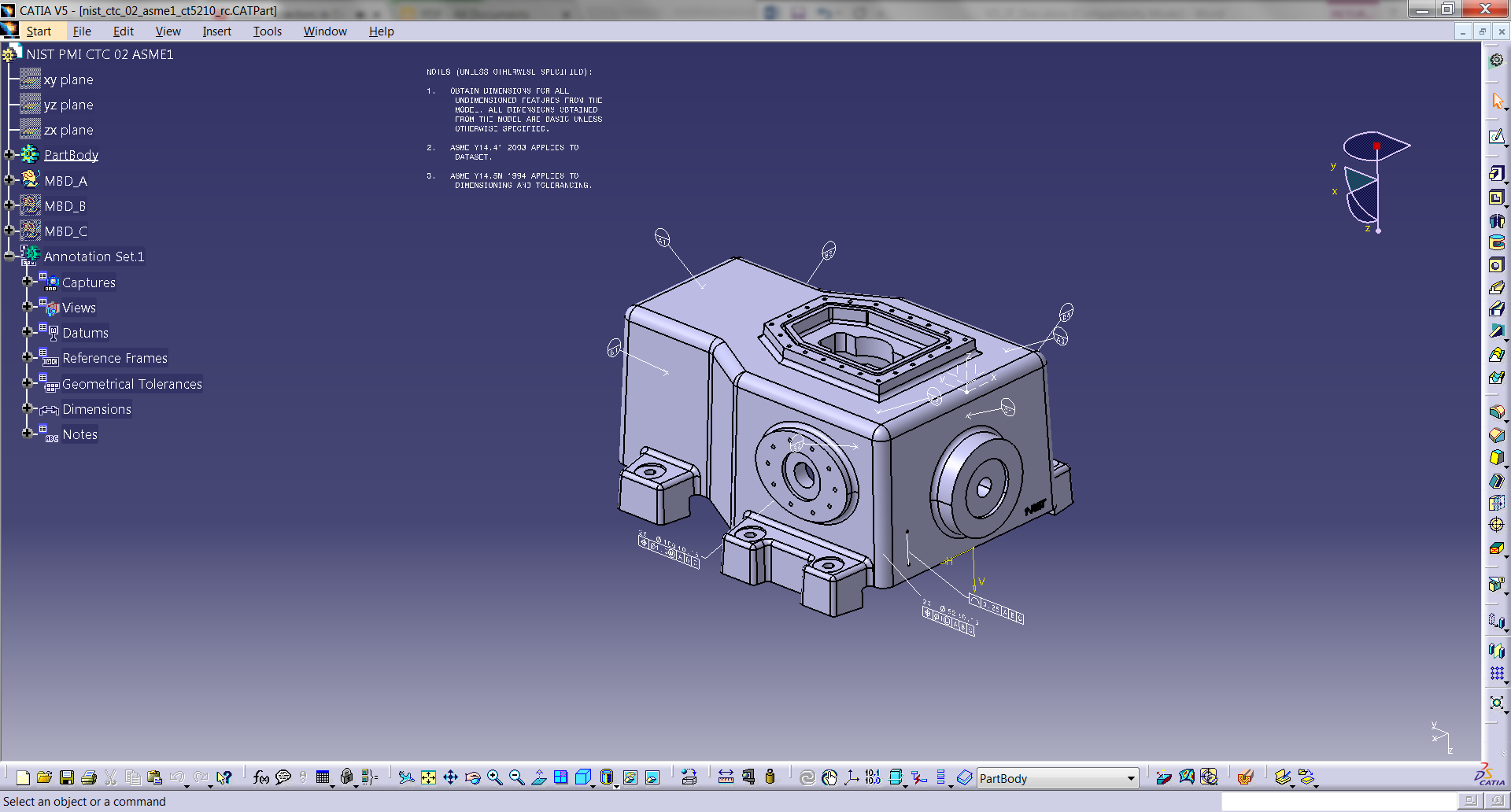
Save As JT
Once CATIA V5 has been started it is possible for a model to be saved to JT. To do this, the user selects the File -> Save As Menu Option. From the file browser window that opens, change the ‘Save as type’ option to be jt (*.jt).
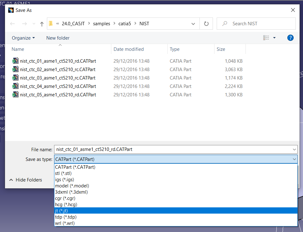
Once selected, press the ‘Save’ button to create the JT data.
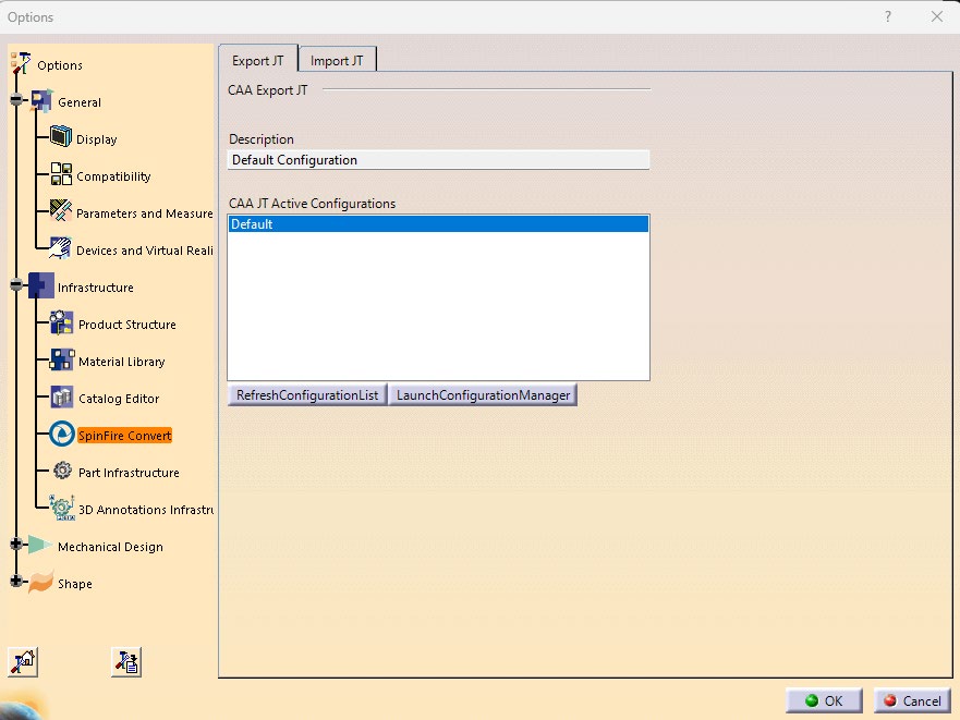
To add a user defined configuration to the process (created from the SpinFire Convert UI), this can be selected from the Tools>Options>Infrastructure>SpinFire Convert>Export JT menu. The process will then use this defined configuration to create the JT data as required.
Open JT Data
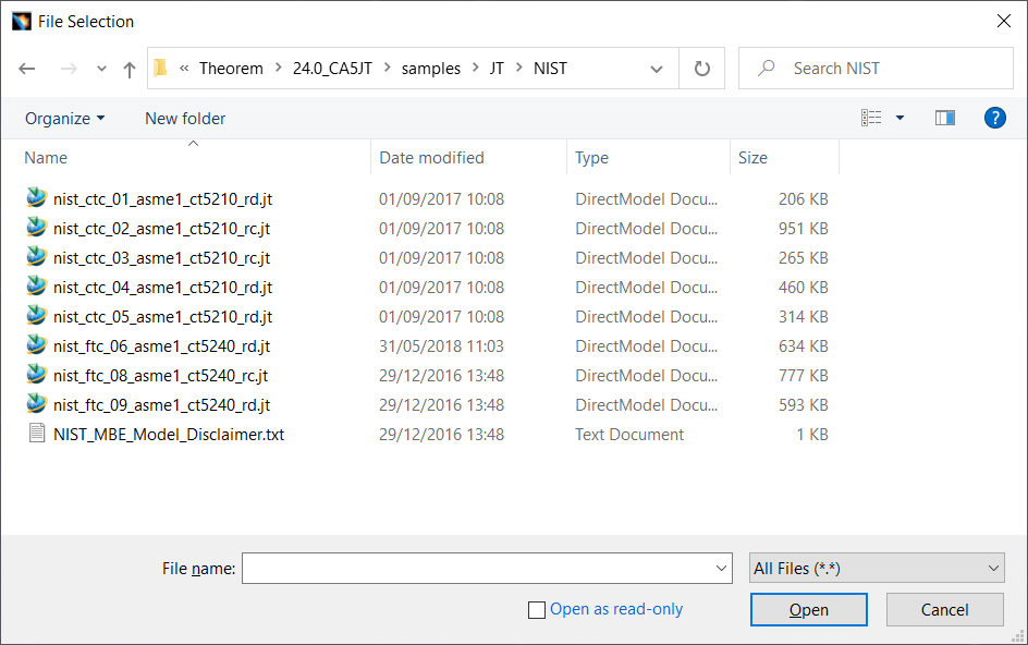
Once CATIA V5 has started it is possible for a model to be imported from JT using the File -> Open menu. Once selected, find the JT data you wish to import into CATIA V5 and select it from the file browser. When ready, press the ‘Open’ button from the menu to import.
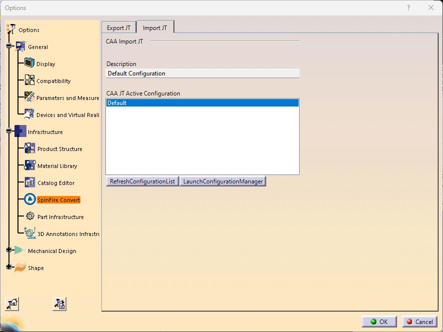
To add a user defined configuration to the process (created from the SpinFire Convert UI), this can be selected from the Tools>Options>Infrastructure>SpinFire Convert>Import JT menu. The process will then use this defined configuration to create the JT data as required.
SpinFire Convert Import and Export
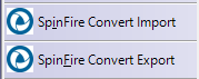
From the ‘File’ menu in CATIA V5 there are two options: ‘SpinFire Convert Import’ and ‘SpinFire Convert Export’. This allows you to import JT data or export to JT from the File menu. Select ‘File’ > ‘SpinFire Convert Export’ or ‘SpinFire Convert Import’ to open the menu.
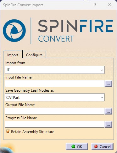
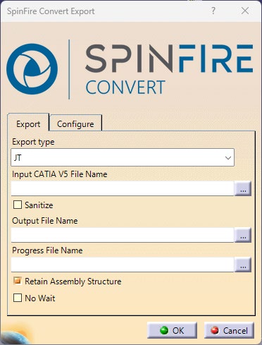
Provide output file name and log file location, then press ‘OK’ to export the data.
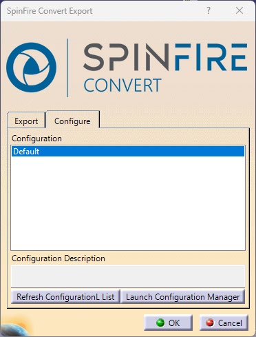
To add a custom configuration, select the ‘Configure’ tab. This allows the user to select a configuration or create a new one by selecting the ‘Launch Configuration Manager’ option. Once a configuration is decided simply to select it from the list for it to be applied.
CATIA V5 Configuration
Introduction
This Appendix details how to define and configure the CATIA V5 and SpinFire Convert environment to work together.
Conventions
- Release of CATIA V5
To indicate a release of CATIA V5 the notation <XX> shall be used. This needs to be replaced with the specific release to be used i.e. 31, 32, 33, 34, 35.
- Platform specific directory
Within the installation directory of CATIA V5 there is a platform specific directory i.e. win_b64. This directory shall be referred to as <OSDS> in this Appendix.
- SpinFire Convert Installation directory
The SpinFire Convert installation directory is set at installation time in the translator
ts_env.batfile. This directory shall be noted as<%TS_INST%>in this Appendix.
CATIA V5 Installation Directory
Upon installation of a CATIA V5 product the user will be asked to specify the installation directory. This is the directory which contains the platform specific <OSDS> directory.
Having selected the CATIA V5 installation directory via the browse button, the installation
process will record the location of the CATIA V5 installation directory in the ts_env.bat file. This
file is located in the SpinFire Convert installation directory. If the location of CATIA V5
subsequently changes, the translator can be guided to the changed location by modifying this
file using a text editor to modify the ts_env.bat that is located in the translator installation
directory.
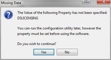
If no entry is included for DSLICENSING a warning dialog will be displayed which warns of the empty field. Selecting Yes to continue will allow the installation to continue.
Running CATIA V5 Translators
Before running the translator the user must run CATIA V5 interactively at least once to configure the CATIA V5 environment and license settings. This can be achieved by running the catia5r<XX>_start script as follows:
<Translator_Installation_Directory>\bin\catia5r<XX>_start.cmd
Once CATIA has been run the Translator can run as described in the relevant product User Guide.
CATIA V5 Environment DIRENV & ENV
The default location for CATIA V5 to store its global environment files is in the global directory:
Windows 10:
C:\ProgramData\DassaultSystemes\CATEnvOr
%APPDATA%\CATEnv
You can find this location by running:
%CATIAV5_INST%\<OSDS>\code\bin\setcatenv -h
The environment files are named in the form CATIA.V5RN.B<XX>.txt
If when installing CATIA V5 the default environment file location was replaced with another
location then this location needs to be indicated to the Translator by defining in the ts_env.bat
the environment variable CATIAV5_DIRENV:
set CATIAV5_DIRENV=/some/directory
If the SpinFire Convert installation is needed to support multiple releases of CATIA, then the user can define release specific locations using:
set CATIAV5R<XX>_DIRENV=/some/directory
SpinFire Convert attempts to create its own environment file called TheoremCatia5R<XX>.txt.
The user must therefore have write permission to the CATEnv directory. If this is not possible an
existing environment file can be specified using the variable CATIAV5_ENV. e.g.
set CATIAV5_ENV=CATIA.V5R35.B35
Note: the extension .txt is not required. The user can specify a release specific name using
CATIAV5R<XX>_ENV e.g.
set CATIAV5R35_ENV=CATIA.V5R31.B35
Checking the CATIA V5 Environment
A script is provided to check that the CATIA V5 environment is set up correctly. In a command window run the command script:
%TS_INST%\bin\checkcatia5r<XX>env.cmd
JT Configuration File
Introduction
A configuration file contains the settings for your translations. The configuration file can be
specified using the command line option -config or -z.
If this is not supplied the following directories will be searched in the specified order for the named configuration files (TS_INST = Installed directory):
tess.configin the directory where the translator is run
tess.configinTS_INST\etcdirectory
Two example config files are provided in the TS_INST\etc directory, a standard tess.config one,
and one that illustrates the options required for large assembly processing,
tessLargeAssm.config which is documented by some comments within it.
The JT configuration file contains various sections, each containing different settings based on the section.
The Setup Section
The setup options in the configuration file define how your files are translated. The setup section is the first part of the configuration file and contains a series of standard translator options.
To edit setup options:
Open an existing configuration file with a text editor.
Edit the configuration file options listed in the table below.
Save the configuration with a .config extension.
Option name |
Keywords |
Example |
|---|---|---|
EAITranslator |
EAITranslator { |
EAITranslator { |
OutputDirectory |
“path to directory” |
OutputDirectory = “/home/<user>/” |
CommonPartsPath |
“path to directory” |
CommonPartsPath = “/myaccount/jtparts/” |
chordalOption |
“RELATIVE” / “ABSOLUTE” |
chordalOption = “RELATIVE” |
structureOption |
“PER_PART” / “MONOLITHIC” / “FULL_SHATTER” |
structureOption = “MONOLITHIC” |
WriteWhichFiles |
“ALL” / “ASSEMBLY_ONLY” / “PARTS_ONLY” |
WriteWhichFiles = “ALL” |
compression |
true / false |
compression = true |
triStripOpt |
true / false |
triStripOpt = false |
seamSewing |
true / false (Note: Not available for Unigraphics) |
seamSewing = true |
seamSewingTol |
any integer |
seamSewingTol = 0.001 |
includeBrep |
true / false |
includeBrep = false |
brepPrecision |
“SINGLE” / “DOUBLE” |
brepPrecision = “SINGLE” |
autoNameSanitize |
true / false |
autoNameSanitize = true |
updateChangedPartsOnly |
true / false |
updateChangedPartsOnly = false |
verboseReporting |
true / false |
verboseReporting = false |
writeAsciiAssembly |
true / false |
writeAsciiAssembly = false |
singlePartsNoAssem |
true / false |
singlePartsNoAssem = false |
smartLODgeneration |
true / false |
smartLODgeneration = true |
autoLowLODgeneration |
true / false |
autoLowLODgeneration = true |
numLODs |
any integer |
numLODs = 3 |
close brace |
} |
} |
The Filter Section
The filter section of the configuration file contains the filename and metadata filtering information. Edit this section if you want to change how the translator sanitizes filenames and filters metadata keys.
To edit filter options:
Open an existing configuration file with a text editor.
Edit the configuration file options from the table below.
Save the configuration with a .config extension.
Option name |
Keywords |
Example |
|---|---|---|
Filter |
Filter { |
Filter { |
FilenameSanitizeSet |
“string of characters” |
FilenameSanitizeSet = “abc123.” |
FilenameSanitizeSetAdd |
“string of characters” |
FilenameSanitizeSetAdd = “4l” |
FilenameSanitizeSetDelete |
“string of characters” |
FilenameSanitizeSetDelete = “c” |
MetadataKey |
“string of characters” |
MetadataKey = “metadata key to exclude” |
close brace |
} |
} |
The Metadata Section
The metadata section sets which metadata to attach to all parts, assemblies and nodes of the model.
Note: Be sure to add these options to the configuration file in pairs: one line to define the metadata key and one line to define the metadata value.
To edit metadata options:
Open an existing configuration file (.CONFIG) in a text editor.
Edit the configuration file options shown in the table below.
Save the configuration with a .config extension.
Option name |
Keywords |
Example |
|---|---|---|
Metadata |
Metadata { |
Metadata { |
AddToParts |
“string of characters” |
AddToParts = “<metadata key>” / AddToParts = “<metadata value>” |
AddToAssemblies |
“string of characters” |
AddToAssemblies = “<metadata key>” / AddToAssemblies = “<metadata value>” |
AddToAllNodes |
“string of characters” |
AddToAllNodes = “<metadata key>” / AddToAllNodes = “<metadata value>” |
close brace |
} |
} |
The Level of Detail Section
The level of detail section of the configuration file contains the tessellation and simplification information for each level of detail in the file.
This section consists of several sets of level of detail (LOD) information, and the number of these sets depends on the number you specified on the numLODs line in the configuration file.
To edit level of detail options:
Open an existing configuration file in a text editor.
Edit the configuration file options listed below.
Save the configuration with a .config extension.
Option name |
Keywords |
Example |
|---|---|---|
LOD |
LOD “lod number” { |
LOD “1” { |
Level |
any integer |
Level = 1 |
Chordal |
any number |
Chordal = 0.001 |
Angular |
any number |
Angular = 25 |
Length |
any number |
Length = 1 |
FeatureSuppression |
any integer |
FeatureSuppression = 0 |
Simplify |
any number |
Simplify = 0.60 |
close brace |
} |
} |
The JT Options Section
The JT Options section of the configuration file contains arguments for JT data.
To edit special options:
Open an existing configuration file with a text editor.
Edit the configuration file options shown in the table below.
Save the configuration with a .config file extension.
Option |
Keyword |
Example |
Default Value |
|---|---|---|---|
JtOptions |
JtOptions { |
JtOptions { |
|
AddSemanticPMI |
true / false |
AddSemanticPMI = true |
true |
AnnotationPlanesViewsetName |
Character string |
AnnotationPlanesViewsetName = “Views” |
Views |
AppendCADExtension |
true / false |
AppendCADExtension = false |
true |
BrepType |
XT / JT / XTJT |
BrepType = true |
XT |
BrepWireframe |
true / false |
BrepWireframe = false |
false |
CadPropertyMappingFile |
Character String |
CadPropertyMappingFile = “%TS_INST%\data\jt\jt_property_mapping.txt” |
|
CollapseHierarchy |
SOLtoDetail / toSets / toPart / SURandFACtoDetail / toPartOptimized / expandPart |
CollapseHierarchy = SOLtoDetail |
SOLtoDetail |
DefaultLayerFilter |
“Character String” |
DefaultLayerFilter = “” |
“” |
EnhanceColour |
true / false |
EnhanceColour = true |
true |
ExpandPart |
true / false |
ExpandPart = false |
false |
ExplodeSolidsToFaces |
true / false |
ExplodeSolidsToFaces = false |
false |
ExternalDetailNaming |
Character string |
ExternalDetailNaming = “” |
“” |
FaceEdgeTol |
Real |
FaceEdgeTol = 0.000006 |
0.000006 |
FixDegenerateEdges |
true / false |
FixDegenerateEdges = true |
true |
FixSmallFeaturesOpenSolids |
true / false |
FixSmallFeaturesOpenSolids = false |
false |
FixSmallFeaturesSolids |
true / false |
FixSmallFeaturesSolids = false |
false |
ForceBodyCreation |
true / false |
ForceBodyCreation = true |
true |
IncrementalSewing |
true / false |
IncrementalSewing = true |
true |
IncrementalSewingNoOfIterations |
Integer |
IncrementalSewingNoOfIterations = 5 |
5 |
JtBrepFixup |
true / false |
JtBrepFixup = False |
False |
LayerFilter |
true / false |
LayerFilter = false |
false |
ModelViews |
true / false |
ModelViews = true |
true |
NameRootNode |
true / false |
NameRootNode = false |
false |
OutputUnits |
mm / cm / m / inches |
OutputUnits = mm |
mm |
ParasolidTolerantModelling |
true / false |
ParasolidTolerantModelling = true |
true |
ParasolidTolerantModellingFactor |
Integer |
ParasolidTolerantModellingFactor = 3 |
3 |
PlmxmlPart |
true / false |
PlmxmlPart = false |
false |
PlmxmlPropertyMappingFile |
Character String |
PlmxmlPropertyMappingFile = “%TS_INST%\data\jt\plmxml_property_mapping.txt” |
|
PmiAttributeMap |
true / false |
PmiAttributeMap = false |
false |
PmiAttributeMapFilename |
“Character String” |
PmiAttributeMapFilename = “” |
|
PmiAttributeSplit |
true / false |
PmiAttributeSplit = false |
false |
PmiGlyphs |
2D / 3D / off |
PmiGlyphs = 3D |
3D |
PmiPolygons |
true / false |
PmiPolygons = false |
false |
ProduceTessellatedOutput |
true / false |
ProduceTessellatedOutput = false |
false |
ReuseSolids |
true / false |
ReuseSolids = false |
false |
SavedViewsViewsetName |
“Character String” |
SavedViewsViewsetName = “Captures” |
Captures |
SewParasolidBodies |
true / false |
SewParasolidBodies = true |
true |
SewParasolidBodiesTol |
Real |
SewParasolidBodiesTol = 0.01 |
0.01 |
ShineSetting |
Integer |
ShineSetting = 30 |
30 |
SimplifyGeometry |
true / false |
SimplifyGeometry = false |
false |
SplitDiscontinuousSurfaces |
true / false |
SplitDiscontinuousSurfaces = false |
false |
StructureOutputType |
JT / PLMXML / PLMXMLJT / STEPBOM / STEPBOM_E2 |
StructureOutputType = JT |
JT |
SubNode |
true / false |
SubNode = false |
false |
UseInstanceNames |
true / false |
UseInstanceNames = false |
false |
FlushRootNodeColour |
true / false |
FlushRootNodeColour = false |
false |
ExplodeSolidIntoFaces |
true / false |
ExplodeSolidIntoFaces = false |
false |
AddSolidNodes |
true / false |
AddSolidNodes = false |
false |
WriteSubAssyFiles |
true / false |
WriteSubAssyFiles = false |
false |
create_cadid |
true / false |
create_cadid = false |
false |
cadid_attr |
Character String |
cadid_attr = “” |
|
cadid_fname |
Character String |
cadid_fname = “” |
|
close brace |
} |
} |
The Catia5 Options Section
The Catia5 Options section of the configuration file contains arguments for Catia5 data.
To edit special options:
Open an existing configuration file with a text editor.
Edit the configuration file options shown in the table below.
Save the configuration with a .config file extension.
Option |
Keyword |
Example |
Default Value |
|---|---|---|---|
Catia5Options |
Catia5Options { |
Catia5Options { |
|
ApplyTrimmingLimits |
true / false |
ApplyTrimmingLimits = false |
false |
AssemblyReportFilename |
Character string |
AssemblyReportFilename = “” |
|
ConvertSurfaceFaceLimits |
On / Off / Powerfill |
ConvertSurfaceFaceLimits = On |
On |
ConvertGenericFilletSurfaceTol |
Real |
ConvertGenericFilletSurfaceTol = 0.0001 |
0.0001 |
ConvertCurvesToNurbs |
true / false |
ConvertCurvesToNurbs = false |
false |
ConvertCurvesToNurbsTol |
Real |
ConvertCurvesToNurbsTol = 0.00001 |
0.00001 |
ConvertSurfacesToNurbs |
None / Fillets / Spheres / Fillets+Spheres |
ConvertSurfacesToNurbs = None |
None |
ConvertSurfacesToNurbsTol |
Real |
ConvertSurfacesToNurbsTol = 0.00001 |
0.00001 |
DecimalSeparator |
dot / comma |
DecimalSeparator = dot |
dot |
FaceOpacity |
true / false |
FaceOpacity = true |
true |
FeatureName |
true / false |
FeatureName = false |
false |
GenerateEmptyPart |
true / false |
GenerateEmptyPart = false |
false |
HybridJT |
true / false |
HybridJT = false |
false |
InstanceNaming |
Character String |
InstanceNaming = “” |
|
MaximumNurbsDegree |
Integer |
MaximumNurbsDegree = 5 |
5 |
MergeCGRVertices |
true / false |
MergeCGRVertices = false |
false |
NonManifold |
true / false |
NonManifold = false |
false |
OpacityZero |
Real |
OpacityZero = 0.1 |
0.1 |
OutputMBD |
true / false |
OutputMBD = false |
false |
OutputMBDLeafNodes |
true / false |
OutputMBDLeafNodes = false |
false |
PrintInfo |
true / false |
PrintInfo = true |
true |
ProcessCaptures |
true / false |
ProcessCaptures = false |
false |
ProcessEsplice |
true / false |
ProcessEsplice = false |
false |
ProcessElectrical |
true / false |
ProcessElectrical = false |
false |
ProcessHybridJT |
true / false |
ProcessHybridJT = false |
false |
ProcessLargeFaces |
HideLargeFaces / AllowLargefaces / DatumFaces / True / False |
ProcessLargeFaces = Datumfaces |
DatumFaces |
ProcessLayers |
ALL_LAYERS / A comma separated list of layer numbers (0-255), using hyphen ‘-’ to separate number ranges. |
ProcessLayers = ALL_LAYERS |
ALL_LAYERS |
ProcessMotion |
true / false |
ProcessMotion = false |
false |
ProcessOpenSolids |
true / false |
ProcessOpenSolids = true |
true |
ProcessPMI |
true / false |
ProcessPMI = false |
false |
ProcessPoints |
true / false |
ProcessPoints = true |
true |
ProcessSolids |
true / false |
ProcessSolids = true |
true |
ProcessWelds |
true / false |
ProcessWelds = false |
false |
ProcessWireFrame |
true / false |
ProcessWireFrame = true |
true |
ReadCachedCGR |
true / false |
ReadCachedCGR = false |
false |
ReadCGREdges |
true / false |
ReadCGREdges = true |
true |
ReadFaceColours |
true / false |
ReadFaceColours = true |
true |
ReadFTAReferenceGeometry |
true / false |
ReadFTAReferenceGeometry = false |
false |
ReadHiddenData |
None / Geometry / Structure / All |
ReadHiddenData = None |
None |
ReadInfiniteAxis |
true / false |
ReadInfiniteAxis = false |
false |
ReadLeafNodeCGR |
true / false |
ReadLeafNodeCGR = true |
true |
ReadMotion |
true / false |
ReadMotion = false |
false |
ReadNOA |
true / false |
ReadNOA = false |
false |
ReadScanData |
true / false |
ReadScanData = true |
true |
ReadSpaceReservations |
true / false |
ReadSpaceReservations = false |
false |
ReduceNurbsSurfaceDegree |
true / false |
ReduceNurbsSurfaceDegree = false |
false |
RetainAssemblyStructure |
true / false |
RetainAssemblyStructure = true |
true |
RetainTrailingZeros |
true / false |
RetainTrailingZeros = false |
false |
SimplifyCurves |
true / false |
SimplifyCurves = false |
false |
SimplifyProgressFile |
true / false |
SimplifyProgressFile = false |
false |
SelectionSets |
true / false |
SelectionSets = false |
false |
SurfaceChecking |
true / false |
SurfaceChecking = false |
false |
SurfaceCheckingTol |
Real |
SurfaceCheckingTol = 0.001 |
0.001 |
TextName |
true / false |
TextName = false |
false |
TopGroupPerBody |
true / false |
TopGroupPerBody = false |
false |
TrimFaceSurfaces |
true / false |
TrimFaceSurfaces = true |
true |
UDFAxisSystems |
true / false |
UDFAxisSystems = false |
false |
ViewContext |
Default3D / Unfolded |
ViewContext = Default3D |
Default3D |
close brace |
} |
} |
The Catia4 Options Section
The Catia4 Options section of the configuration file contains arguments for Catia4 data.
To edit special options:
Open an existing configuration file with a text editor.
Edit the configuration file options shown in the table below.
Save the configuration with a .config file extension.
Option |
Keyword |
Example |
Default Value |
|---|---|---|---|
Catia4Options |
Catia4Options { |
Catia4Options { |
|
CatiaAssemblyPartsPath |
ASIS / SET / LAYER / ENTITYTYPE / VIEW |
ColourVisualizationMode = ASIS |
ASIS |
ColourVisualizationMode |
Character string |
AssemblyReportFilename = “” |
|
FacetColour |
true / false |
FacetColour = false |
false |
GroupPipes |
groupPipelines / groupPipes / ungroupPipelines |
GroupPipes = groupPipelines |
groupPipelines |
ProcessEntityNames |
ALL_ENTITIES / A comma separated list of ENTITY names |
ProcessEntityNames = ALL_ENTITIES |
ALL_ENTITIES |
ProcessFAC |
true / false |
ProcessFAC = true |
true |
ProcessGPR |
true / false |
ProcessGPR = true |
true |
ProcessLayers |
ALL_LAYERS / CURRENT_LAYER_FILTER / A comma separated list of layer numbers (0-255), using hyphen ‘-’ to separate number ranges. |
ProcessLayers = ALL_LAYERS |
ALL_LAYERS |
ProcessModelNumber |
Integer |
ProcessModelNumber = 1 |
1 |
ProcessNOSHOW |
true / false |
ProcessNOSHOW = false |
false |
ProcessNRBS |
true / false |
ProcessNRBS = true |
true |
ProcessPIP |
true / false |
ProcessPIP = true |
true |
ProcessPOI |
true / false |
ProcessPOI = true |
true |
ProcessSetNames |
ALL_SETS / A comma separated list of SET names |
ProcessSetNames = ALL_SETS |
ALL_SETS |
ProcessSKI |
true / false |
ProcessSKI = true |
true |
ProcessSOL |
true / false |
ProcessSOL = true |
true |
ProcessSTR |
true / false |
ProcessSTR = true |
true |
ProcessSUR |
true / false |
ProcessSUR = true |
true |
ProcessWireFrame |
true / false |
ProcessWireFrame = true |
true |
UseColorMethod |
AS_FILED / SET / LAYER / ENTITY |
UseColorMethod = AS_FILED |
AS_FILED |
close brace |
} |
} |
The General Options Section
The General Options section of the configuration file contains general arguments.
To edit special options:
Open an existing configuration file with a text editor.
Edit the configuration file options shown in the table below.
Save the configuration with a .config file extension.
Option |
Keyword |
Example |
Default Value |
|---|---|---|---|
GeneralOptions |
GeneralOptions { |
GeneralOptions { |
|
MassProperties |
true / false |
MassProperties = false |
false |
ProgressFileInformation |
true / false |
ProgressFileInformation = true |
true |
ProgressFileWarnings |
true / false |
ProgressFileWarnings = true |
true |
ReportFilename |
Character String |
ReportFilename = “%TEMP%\report1.log” |
|
AdvancedOptions |
Character String |
AdvancedOptions = “” |
|
close brace |
} |
} |
Error Codes
Common Error Codes
When processing data, the command screen or log file will show a return code as a status of the translation. These are detailed below.
Return Code |
Description |
|---|---|
0 |
Success |
1 |
Issues during write leg such as incomplete run or no arguments given |
2 |
Issue obtaining license |
3 |
Input file argument issue or failure to open Progress File |
4 |
Issue during read including no entities read |
5 |
Failure to located secondary process (aka vwr_3dpdf.exe or vwr_jt.cmd) |
7 |
Failure to open CATIA V5 document |
8 |
Failure to find root node of CATIA V5 document |
9 |
Failure to start CATIA V5 session |
10 |
catia5cadverter.dll version doesn’t match the catia5_XXX.exe |
11 |
CATIA V4 data given as input file but bi _V4MAIN license available |