User Guide
Using the Product
Default Translations
Default Translation – via the Unified Interface
The Unified Interface can be started via the Start Menu – if a shortcut was added during installation.
Alternatively, the Unified Interface can be run via a Windows Explorer selection in:
<UI_installation_directory>\bin\Unified_Interface.cmd
The following interface will be launched:
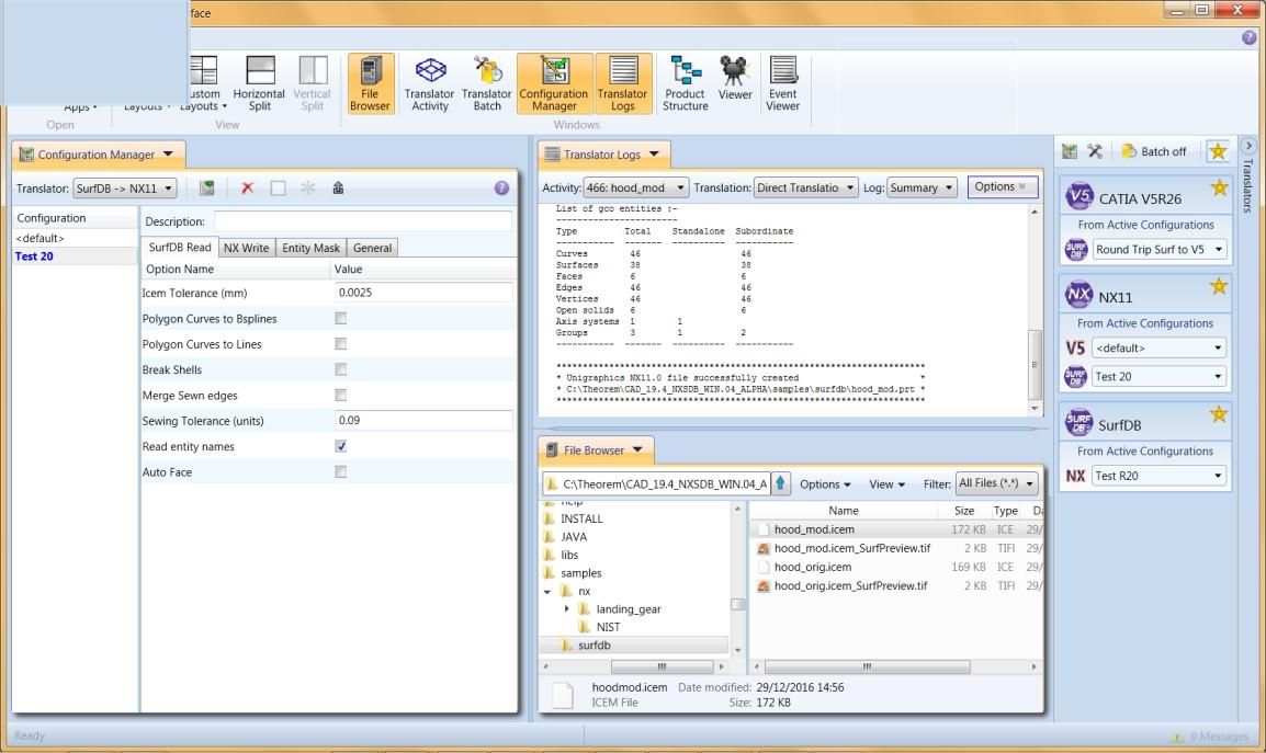
The default layout is split into 4 primary areas, which can be altered to the users preference:
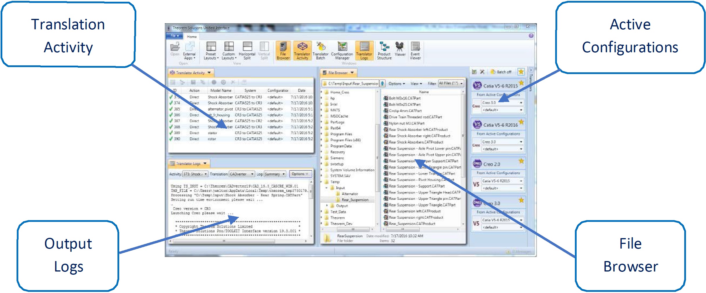
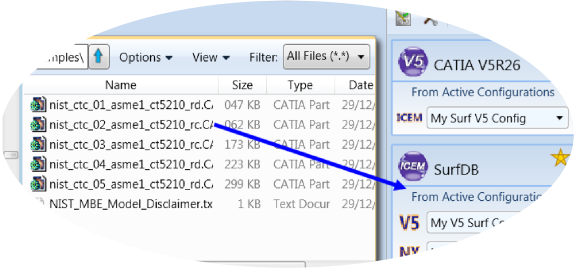
The simplest way to translate from Surf or V5 is to drag a file from the file Browser Pane on to the Active Configurations for the translation you require.
On completion, the Unified Interface will display the activity information and details from the log file created during the translation, if requested, in the Translation Activity and Output Log panes, respectively.
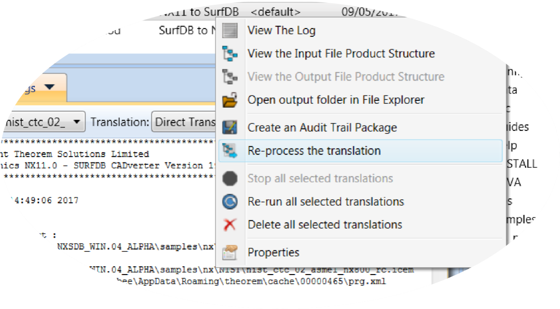
The generated output data can be located by selecting the translation from the Activity pane and opening the output folder. Other tasks such as Re-processing the translation are also possible from this menu:
Default Translation – via the Command Line
Running a translation via the command line can be carried out via the cad_run_UI.cmd file
located in the <installation_directory>\bin directory. The format of the command is as
follows when translating from Surf to V5:
<Translator_installation_directory>\bin\cad_run_UI.cmd SurfDB_CATIA5[XX] -i <input_file> -o <output_file> -c "<configuration name>"
The format of the command is as follows when translating from V5 to Surf:
<Translator_installation_directory>\bin\cad_run_UI.cmd SurfDB_CATIA5[XX] -i <input_file> -o <output_file> -c "<configuration name>"
Where <configuration name> is the name of a Configuration e.g. "My SURF V5 Config"
(see below).
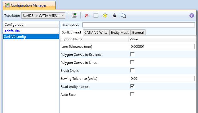
(Note! Replace the [XX] seen in the example with the version of V5 that you are using. E.g. for V5R31, change to CATIA531):

The example above will translate a Surf sample file provided within the installation and produce the following screen output:
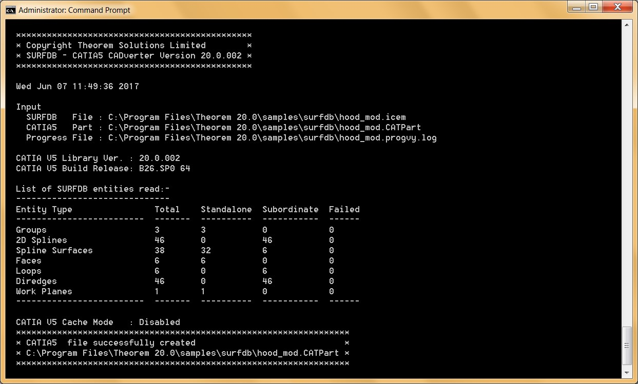
The file will be output to the target location. In this case:
C:\Program Files\Theorem 20.0\samples\surfdb\NIST\hood_mod.CATPart
CADverter Customization
CADverter allows the information that is read from the source system and written to the target system to be tailored via a set of user specified arguments. Commonly used arguments are supported via the Unified Interface, with Advanced Arguments being described within this document for use in the Unified Interface or via the Command Line invocation.
General Notes for Surf to V5
The SURFDB Ellipse entity holds both the Arc and Ellipse definitions. The appropriate CATIA entity will be created.
Conversion of the Polygon Curve is dependant upon whether the ‘mc_to_bsp’ and ‘mc_to_lin’ options have been used. If none of these options are used then Polygon Curves are ignored. They can both be used together if required.
Standalone Spline Surfaces are always faced as CATIA V5 always has topology on geometry.
Shells will be written as separate Faces. If the ‘break_shells’ option is used or the Shell sewing process fails, the shell will be formed by a Surface Join.
Common Options for Surf to V5
Within the Configuration Manager pane of the Unified Interface, arguments that can be specified when publishing Surf data into V5 are grouped into 4 areas:
Surf Read – Those arguments that affect how data is read from Surf
V5 Write – Those arguments that affect how the data is written to V5
Entity Mask – Those arguments that allow specific read entities to be masked
General – Those arguments that are common to ALL Publishing activities regardless of source data
Surf Read Arguments
The image below shows the Surf Read arguments that are available, with their default settings:
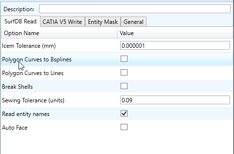
Each of these options is described below:
Option |
Description |
|---|---|
Icem Tolerance |
This tolerance is used in the translation when checking Face base surfaces for degeneracy and when fitting 3D edge curves. This can be altered with this option if required (Default is 0.000001m). Command Line Syntax:
|
Polygon Curves to B-splines |
Converts polygon curves to b-splines. (Default is OFF). Command Line Syntax:
|
Polygon Curves to Lines |
Converts polygon curves to lines. (Default is OFF). Command Line Syntax:
|
Break Shells |
Any Shells encountered in the translation will be converted to UG Trimmed Surfaces (Solids). If this option is used then Shells will be broken into separate Faces. (Default is OFF). Command Line Syntax:
|
Sewing Tolerance |
When a Shell is read it has to be sewn together (unless the break_shells option has been used). (Default is 0.09/units). Command Line Syntax:
|
Don’t Read Names |
By default entity names are read from V5. (Default is Off). Command Line Syntax:
|
Auto Face |
This option specifies that standalone Bezier patches should be automatically faced. (Default is Off). Command Line Syntax:
|
V5 Write Arguments
The image below shows the Write V5 arguments that are available, with their default settings:
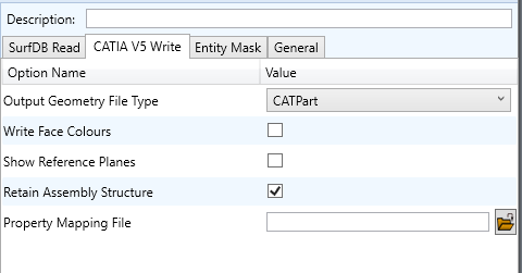
Each of these options is described below:
Option |
Description |
|---|---|
Output Geometry Type |
Allows the user to define the file format to be created. Options are; CATPart, model, cgr, igs, CATShape, Tesselated. Default is CATPart. Command Line Syntax – the corresponding settings in order are:
|
Write Face Colours |
Reads face colour but this can lead to a performance hit. The alternative option is apply the colour from the solid. Default is on. Command Line Syntax:
|
Show Reference Planes |
Shows planes. Default is Off. Command Line Syntax:
|
Surf to V5 Entity Masking Arguments
The image below shows the Masking arguments that are available, with their default settings:
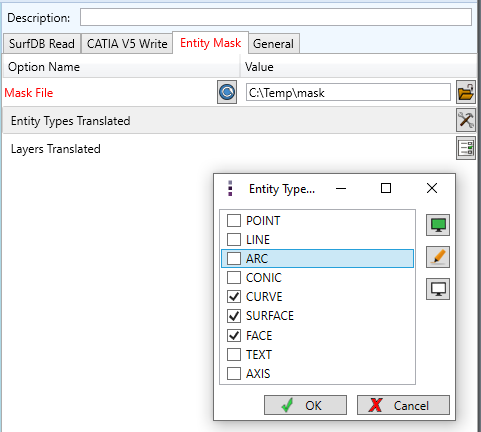
Each of these options is described below:
Option |
Description |
|---|---|
Mask File |
Specifies the Mask File to be written to, that can be referenced by future translations. A Mask file MUST be specified if masking is required. The first line in this file is OFF ALL ENT: Command Line Syntax:
|
Entity Types Translated |
Specifies a selection list from which to select which entity types are to be processed. The following types are available: “POI”,”LIN”,”ARC”,”CON”,”CUR”,”ISO”,”SUR”,”FAC”,”TEX”,”AXI” Command Line Syntax:
|
Layers Translated |
Specifies a selection list from which to select which layers are to be processed. Command Line Syntax:
|
Surf to V5 General Arguments
The image below shows the General arguments that are available, with their default settings:
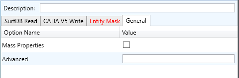
Each of these options is described below:
Option |
Description |
|---|---|
Advanced |
Allows any of the Command Line Advanced arguments documented below to be passed to the Unified Interface invocation. |
There are a number of arguments that may be provided to the CADverter. They can be supplied in any order. Those marked in red italics are on by default when running from within the ICEM SURFDB GUI. These options are chosen to maintain the data quality with respect to surface and curve parameterization etc. rather than ensure greatest success on conversion.
Option |
Description |
|---|---|
Advanced |
Allows any of the Command Line Advanced arguments documented below to be passed to the Unified Interface invocation |
|
This tolerance is used in the translation when checking Face base surfaces for degeneracy and when fitting 3D edge curves. The default icem_tol is 0.0025 mm or 0.0001 inch. If required, this can be altered with this option if required. |
|
This specifies that Polygon Curves read from the SURFDB file should be
converted to linear B-Splines. Both |
|
This option specifies that Polygon Curves read from the SURFDB file should
be converted to Line entities. Both of |
|
Specifies that any Shells encountered will be broken into separate Faces in the translation. |
|
When a Shell is read its subordinate faces have to be sewn together. This is achieved by the join operator which checks if all entities are within the defined tolerance. The tolerance by default is 0.001 mm. If the check fails the join are not successful. |
|
When the join is created the angle between connecting edges can be checked to see if they are within a given angle. By default the angle is 0.5 degrees. If the check fails the join are not successful. |
|
When the join is created the tangency between adjacent edges can be checked. If the check fails the join are not successful. |
|
When the join is created the connexicity between connecting edges can be checked. If the check fails the join are not successful. |
|
When a composite curve is read its subordinate curves have to be sewn together. This is achieved by the join operator which checks if all entities are within the defined tolerance. The tolerance by default is 0.001 mm. If the check fails the join are not successful. |
|
When the join is created the angle between adjacent curves can be checked to see if they are within a given angle. By default the angle is 0.5 degrees. If the check fails the join are not successful. |
|
When the join is created the tangency between connecting edges can be checked. If the check fails the join are not successful. |
|
When the join is created the connexicity between connecting edges can be checked. If the check fails the join are not successful. |
|
By default entity conversion messages are output to the progress file, this option restricts the output to only errors and warnings. |
|
By default, 2D edge curves for faces are not written directly to CATIA V5. They are created in CATIAV5 by projecting the 3D edge curve onto the surface. This option allows the parameterized NURBS representation to be maintained as long as the underlying surface was originally of BEZIER or NURBS type. |
|
By default, entity names will not be read. If this option is used the names will be read and passed to CATIA V5. |
|
By default face supporting surfaces are trimmed back to the face boundary. This option will cause these surfaces not to be trimmed during the translation. |
|
By default when an axis system is created it is shown. This option will allow the axis system to be hidden. |
|
By default groups are not read. This option allows the groups to be read and converted to bodies in CATIA V5 to preserve the hierarchy. |
|
By default standalone surfaces have topology added to them in CATIA5.
However there is no control on the curve types created. This option adds
the topology on the read leg and therefore the edge curves are of a known
type. Needs to be used in conjunction with |
|
By default, if the CATIA V5 write encounters faces which are based on order
2x2 B-Spline Surfaces, it checks the surfaces to see if they are planar and
if so will convert them to Planes to save space. If such surfaces should be
kept as B-Spline Surfaces then the |
|
The default behaviour of reporting an error if an attempt was made to create a curve whose length is less than the CATIA V5 resolution values has been altered. This option reinstates this error reporting to the progress file. |
|
The default behaviour is to leave standalone planes in show mode. This option cause them to be hidden. |
|
The default behaviour is to maintain the NURBS surface and curve parameterization form the input but this may not be ideal for CATIA V5. This option allows CATIA V5 to optimize the parameterization on NURBS surfaces, curves or both. |
|
The default behavior is to split edges that pass through surface degeneracy’s. This option stops this. |
|
To improve the success rate of face creation and limit the amount of data created the underlying surfaces are trimmed back to the face extents and for NURBS surfaces a margin of error is allowed to improved the success in projecting the 3D edge curves onto the surface to create the 3D edge curves. These option alter this behavior. |
|
Causes NURBS curves to be simplified to analytics if possible. |
|
Causes analytic surfaces to be created as NURBS. |
|
Stops the removal of double edge curves i.e. two adjacent edge curves that run between the same vertices. |
|
Stops the fixing up of 3D edges curves including trimming back to vertices. |
General Notes for V5 to Surf
Ellipses with hmaj/hmin >1000 are converted to 3D Splines due to loss of precision during conversion.
SURFDB does not support the Parabola or Hyperbola so they are converted to 3D Splines.
Standalone Planes are ignored unless the ‘pln_to_wpln’ option is used in which case they are converted to Work Planes.
Planes that are base surfaces of Faces will be converted to Spline surfaces.
Face 3D edges that are Circular Arcs will be converted to 3D Splines.
Since the SURFDB file does not support Solid Entities, any Solids encountered will be written to the SURFDB file as a collection of Faces.
If a mirrored Axis is encountered it will NOT be converted as the SURFDB file does not support mirrored axes.
Axis names are converted to upper case.
Common Options for V5 to Surf
Within the Configuration Manager pane of the Unified Interface, arguments that can be specified when publishing Surf data into V5 are grouped into 4 areas:
Surf Write – Those arguments that affect how the data is written to Surf
Entity Mask – Those arguments that allow specific read entities to be masked
General – Those arguments that are common to ALL Publishing activities regardless of source data
Surf Write Arguments
The image below shows the Surf Write arguments that are available, with their default settings:
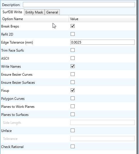
Each of these options is described below:
Option |
Description |
|---|---|
Break Breps |
By default, Brep Solids (as opposed to Open Solids) will be broken down into
their constituent Faces during conversion. By using the Command Line Syntax:
|
Refit 2D |
Optional. Specifies that faces read from UG should not have their 2D parametric edges refitted before being written to SURF but as far as possible, should be kept as they are from UG. This argument also increases the speed of processing because the translator does not have to perform the refitting process. If this option is not used then Face edges will be checked to see if splitting is required and whether the parametric loops are closed correctly. Default is OFF. Command Line Syntax:
|
Edge Tolerance (mm) |
There are 4 conditions for which 2D edge curves will be refitted for a particular Face during translation:
Default is 0.0025. Command Line Syntax:
|
Trim Face Surfaces |
Faces can be based on surfaces that are significantly larger than the face
requires. By default, the translator will leave such surfaces as they are
(which can lead to tolerance and extent problems in the receiving system).
By using the Command Line Syntax:
|
Ascii |
Creates reference planes. Default is OFF. Command Line Syntax:
|
Write Names |
By default, each entity will be written to the output file with its name (if
it has one). If the Command Line Syntax:
|
Ensure Bezier Curves |
All spline curves that are single segment will be checked to ensure that they are in Bezier form, if possible. Default is OFF. Command Line Syntax:
|
Ensure Bezier Surfaces |
All single patch surfaces will be checked to ensure that they are in Bezier form, if possible. Default is OFF. Command Line Syntax:
|
Fixup |
This option specifies that the check for effectively zero length parametric segments in B-Spline Curves should NOT be performed. If the option is not used then by default the check IS performed and any segments encountered which are too short are removed. Default is ON. Command Line Syntax:
|
Polygon Curves |
This option will check for degree 1 B-Spline curves that are not part of a Face and convert them to Polygon Curves. The default is to convert such curves to BSplines in the normal way. Default is OFF. Command Line Syntax:
|
Planes to Work Planes |
Independent Planes are written to Work Planes in SURF. Default is ON. Command Line Syntax:
|
Planes to Surfaces |
By default, the translator will convert free planes in V5 to Work planes in SURF unless the argument ‘no_pln_to_wpln’ is specified, in which case they are ignored. If turned on, then Bsurfs will be created. Default is OFF. Command Line Syntax:
|
Side Length (mm) |
Related to pln_to_srf. Default is 1. Command Line Syntax:
|
Unface |
Trims the surface back to the face boundary, if the value set is in the tolerance of the surface isoparms. Default is OFF. Command Line Syntax:
|
Unface Tolerance (mm) |
Related to unface. Default is 0.00001. Command Line Syntax:
|
Check Rational |
Check to ensure incoming surfaces are rational. NOTE this can take will take a longer time to process if switched on. Default is OFF. Command Line Syntax:
|
V5 to Surf Entity Masking Arguments
The image below shows the Masking arguments that are available, with their default settings:
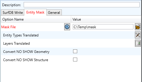
Each of these options is described below:
V5 to Surf General Arguments
The image below shows the General arguments that are available, with their default settings:
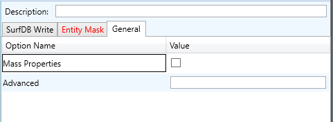
The option is described below:
Option |
Description |
|---|---|
Advanced |
Allows any of the Command Line Advanced arguments to be passed to the conversion process. |
Command Line Advanced Arguments
Any of the advanced arguments can be added to the Command Line Invocation or to the General->Advanced field when run from within the User Interface.
Surf Advanced Arguments
Argument |
Description |
|---|---|
|
Converts curves to NURBS form. Default is OFF. Command Line Syntax:
|
|
Converts surfaces to NURBS form. Default is OFF. Command Line Syntax:
|
|
Reads face opacity. This can lead to a performance degradation. Default is OFF. Command Line Syntax:
Allows definition of tolerance below which an entity is considered to be totally transparent. |
Translating Interactively from within Surf
The Surf to V5 translator allows an active Surf Part or Assembly to be exported directly into V5 format or an V5 Part or assembly to be imported directly from within the Surf application.
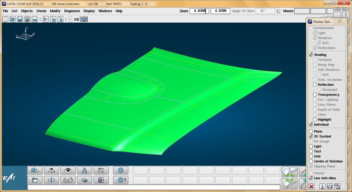
In order to translate from within Surf, the Surf application must be started.
The appropriate KDdat files must be modified to set the environment up to successfully create good quality data depending on the translator use. The modification of these files is explained later in this document in the Surf Configuration – Configuring Surf. Surf can then be started using the standard commands.
Export
Once Surf has been started and a model loaded, the active Part or Assembly can be exported to V5.
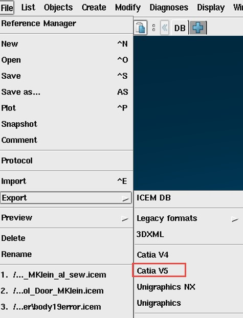
In order to export, the user selects the File -> Export Menu Option:
Which in turn launches the Export panel:
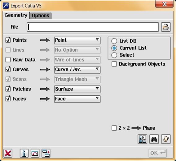
The File field may be prepopulated. However, this can be modified prior to selecting the OK button.
The Options tab is shown below, for further information please refer to the relevant section of the ICEM Surf documentation.
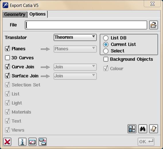
On selecting OK the on the Export Panel, the active Part or Assembly will be written to CATIA V5 using the selected output directory.
Import
Once Surf has been started, V5 data can be imported into Surf.
In order to import, the user selects the File -> Import Option:
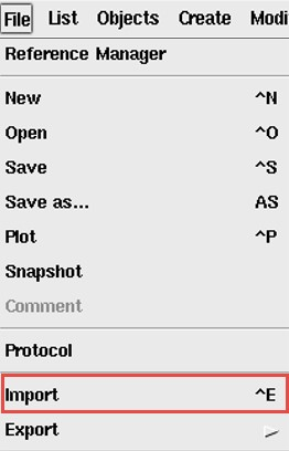
Which in turn launches the Import File Browser panel:
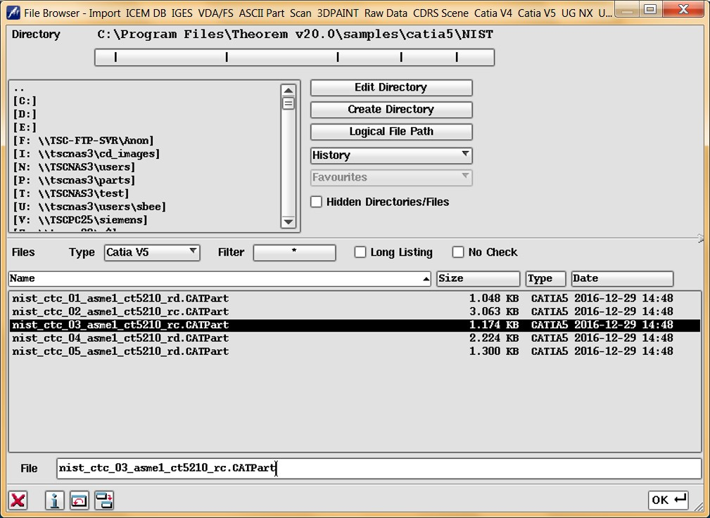
The Import From option allows the user to select the V5 part or assembly to import. Selecting the OK button, brings up the Import dialog.
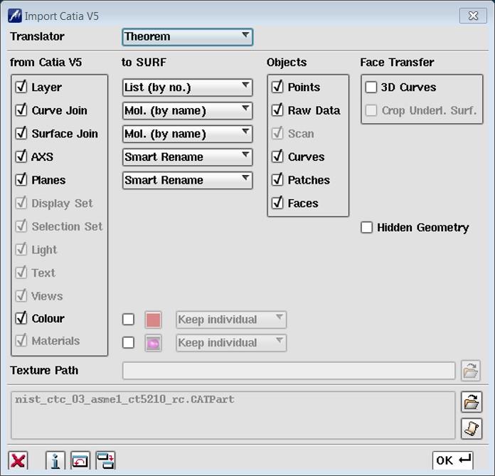
Selecting OK the on the Import Panel import V5 data will be imported into Surf and the data saved using the input into the selected output directory. For more information please refer to the relevant section of the ICEM Surf documentation.
Surf Configuration
Introduction
For the Surf product to work with a Theorem product for import/export it is necessary for the system administrator to make some modifications to directive files with the Surf product. These files are named:
kddat_to_catia5_directive.txt
catia5_to_kddat_directive.txt
For a default Surf 2017 installation their location is in:
C:\Program Files\Dassault Systemes\ICEM Surf\icemsurf-2017.2\win_b64\reffiles
The partial contents of the catia5_to_kddat_directive.txt file are shown below.
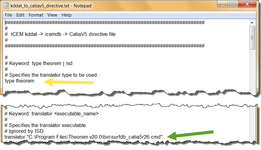
Two scripts control the launching of the Theorem:
%TS_INST%\bin\catia5r[XX]_surfdb.cmd
%TS_INST%\bin\surfdb_catia5r[XX].cmd
As these scripts source the Theorem environment which includes the V5 ROOT DIR they can be used directly in the definition within the directives files. In the above diagram the translator type should be set to theorem (default is ISD). The translator should point to the cmd file for the appropriate version of CATIA V5. In the example shown this is R26.
Similar change are needed to the kddat_to_catia5r[XX]_directive.txt to enable the converter
to point to the correct export translator type and cmd file e.g:
C:\Program Files\Theorem\21.2\bin\surfdb_catia5r26.cmdDefault Values
The original products were written to support the premise that original Surface Design data would be written into V5 for final detailing. It was also seen to be important that these surfaces should not change, if possible, to keep the original design intent.
Current design practices of using scanned data or convergent modelling means that the data often starts off in the CAD system and passed to Surf to create the surface required.
If the surface then needs to be detailed, it may then need to be passed back to the CAD system. In an iterative Design process, this return trip may happen several times.
Because of the different modelling philosophies between CAD and Surface design, and exact and tolerant modelling techniques, a number of compromises may have to be made between success and accuracy during the translation.
There are two sets of recommended defaults to suit the different design practices used. Please note that each customers data may differ in its requirements for translation, so the defaults used are advisory only.
Configuration Files
From revision 21.1 the customer is able to use UI generated configurations on the command line, this functionality will be expanded in future revisions.
For printing a config file argument contents:
The Configuration files are of xml format. If you want a list of the contents in text form, then the following command can be used:
C:\Program Files\Theorem\21.1\bin\cad_run.cmd -a "My V5 SURF Config" -o C:\temp\contents.txt
For running CAD_RUN with a config:
C:\Program Files\Theorem\21.1\bin\cad_run_UI.cmd CATIA526_SurfDB -c "My V5 SURF Config"
-i C:\Program Files\Theorem\21.1\samples\catia5\NIST\nist_ctc_01_asme1_ct5210_rd.CATPart
-o C:\Program Files\Theorem\21.1\samples\catia5\NIST\nist_ctc_01_asme1_ct5210_rd.icem
Using Defaults:
"C:\Program Files\Theorem 21.1\bin\cad_run_UI.cmd" CATIA526_SurfDB
-i "C:\PPC\Customers\XXXCo\R20 Tests_020617\Example.CATPart"
-o "C:\PPC\Customers\XXXCo\R20 Tests_020617\Example.icem"