User Guide
Running the Product
Once configured and licensed, the product is ready to be run.
There are 2 distinct ways of running the translator:
Via the Theorem Unified Interface
The Unified Interface offers a Desktop Environment that allows CAD and Visualization data to be viewed pre and post translation
Via the Command Line
The Command Line Interface provides a direct method of invoking the translator. It can be used via a DOS shell or called via a third party application as part of a wider process requirement.
Using the Product
Default Translations
Default Translation – via the Unified Interface
The Unified Interface can be started via the Start Menu – if a shortcut was added during installation.
Alternatively, the Unified Interface can be run via a Windows Explorer selection in:
<UI_installation_directory>\bin\Unified_Interface.cmd
The following interface will be launched:
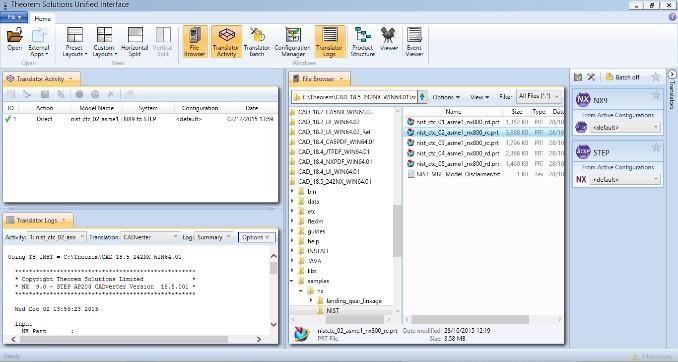
The default layout is split into 4 primary areas, which can be altered to the user’s preference:
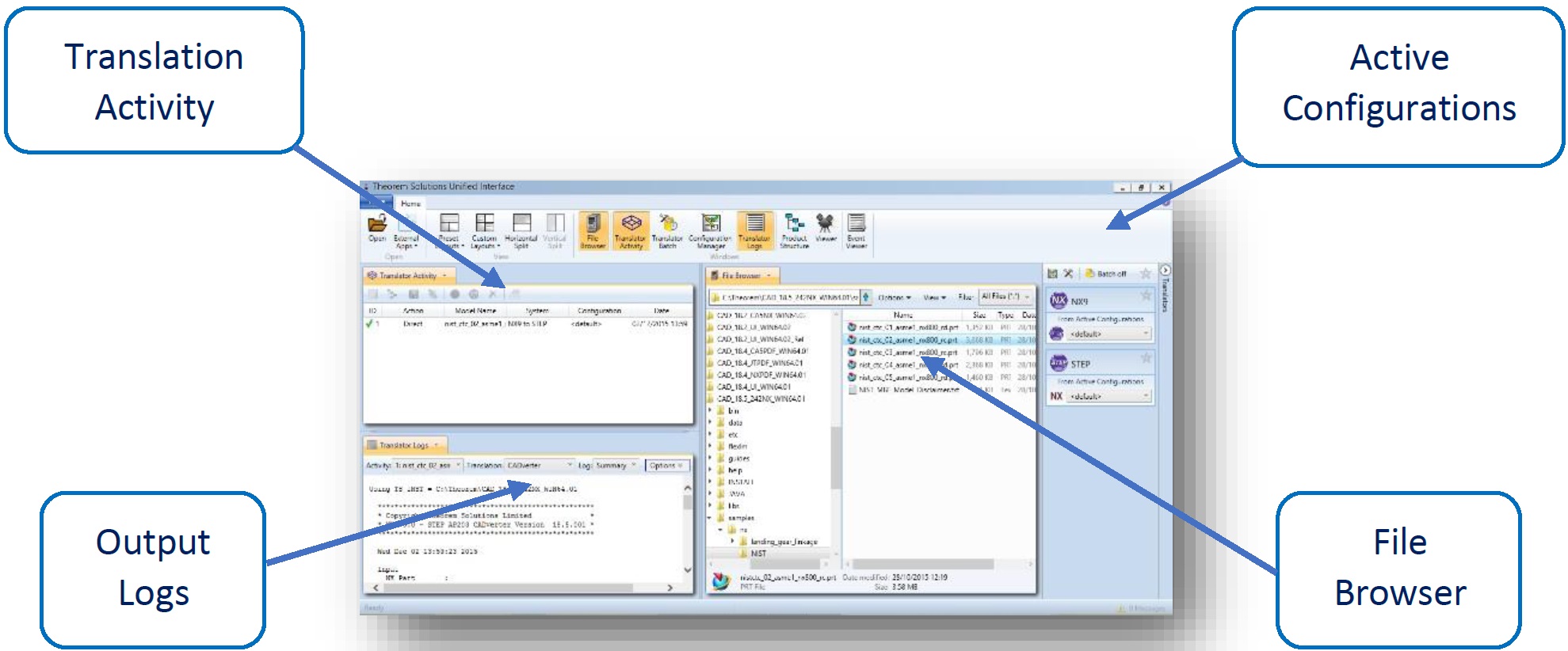
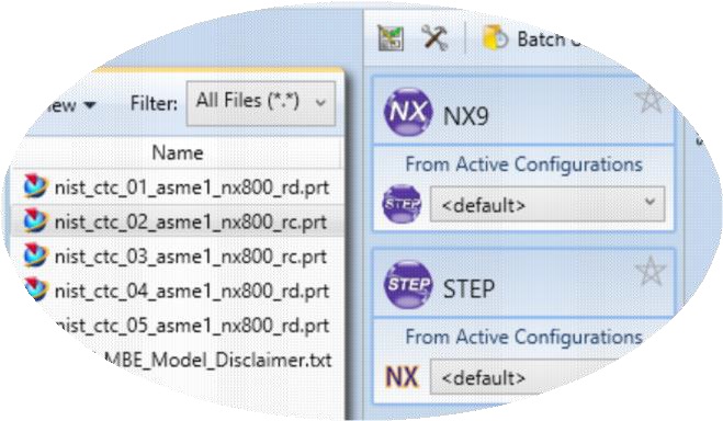
The simplest way to translate from STEP or NX is to drag a file from the file Browser Pane on to the Active Configurations for the translation you require.
On completion, the Unified Interface will display the activity information and details from the log file created during the translation, if requested, in the Translation Activity and Output Log panes, respectively.
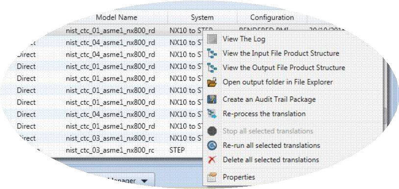
The generated output data can be located by selecting the translation from the Activity pane and opening the output folder:
Default Translation – via the Command Line
Running a translation via the command line can be carried out via the cad_run.cmd file
located in the <installation_directory>\bin directory. The format of the command is as
follows when translating from STEP to NX:
<Translator_installation_directory>\bin\cad_run.cmd STEP_UnigraphicsNX [XX] <input_file> <output_file>
The format of the command is as follows when translating from NX to STEP:
<Translator_installation_directory>\bin\cad_run.cmd UnigraphicsNX[XX]_STEP <input_file> <output_file>
(Note! Replace the [XX] seen in the example with the version of NX you are using. E.g. for NX9 change to UnigraphicsNX9):

The example above will translate a STEP sample file provided within the installation and produce the following screen output:
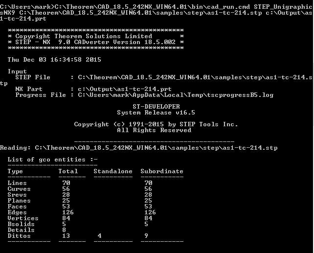
Note! This is only the top of the screen output.
The file will be output to the target location. In this case:
C:\Output\as1-tc-214.prt
CADverter Customization
CADverter allows the information that is read from the source system and written to the target system to be tailored via a set of user specified arguments. Commonly used arguments are supported via the Unified Interface, with Advanced Arguments being described within this document for use in the Unified Interface or via the Command Line invocation.
Common Options for STEP to NX
Within the Configuration Manager pane of the Unified Interface, arguments that can be specified when publishing STEP data into NX are grouped into 4 areas:
STEP Read – Those arguments that affect how data is read from STEP
NX Write – Those arguments that affect how the data is written to NX
Entity Mask – Those arguments that allow specific read entities to be masked
General – Those arguments that are common to ALL Publishing activities regardless of source data
STEP Read Arguments
The image below shows the STEP Read arguments that are available, with their default settings:
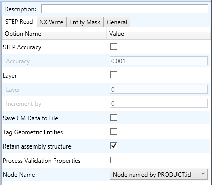
Each of these options is described below:
Option |
Description |
|---|---|
STEP Accuracy |
This option is used to specify the tolerance value used by the CADverter to decide whether a curve or surface is closed, or a surface is degenerate. For most cases, the default value of 0.001 mm will be adequate. Default is OFF. Command Line Syntax:
|
Layer |
This option may be used to define layer information, if the input STEP File does not contain layering, for processing into the receiving system. Default is OFF. You can specify either the one and only layer that the STEP data is to be put on to (if the Incremental Layer option is not used), or the start layer if other than zero is required (if the Incremental Layer option is used). For example, if a layer of 3 is specified and the Incremental Layer option is not used, then all geometry will be written to layer 3. If you specify a layer of 3 and set a value in the Incremental Layer option, then the geometry from each Shape Representation encountered in the STEP file will be put on a new layer starting from layer 3, incremented by the value entered each time. NOTE: If a STEP AP203 or STEP AP214 file containing Colours and Layer Modular extension data is read, the values in the file will take precedence over the values entered by this option. Command Line Syntax:
|
Save CM Data to File |
STEP files contain more than just geometric data. In addition it can contain Configuration Management Data (also known as CM Data, or PDM information), such as the names of people and organisations fulfilling various roles (design creator etc.). By using this option this non-geometric data will be printed out into a CM Data File, which conforms to the Theorem Solutions CM Data File format. The CM Data File will be
named Command Line Syntax:
|
Tag Geometric Entities |
Many CAD systems have the capability to apply TAG values to geometric entities. This option instructs the CADverter to use the value found in the ‘name’ field of the Geometric Representation Item as this TAG value. Default is OFF. Command Line Syntax:
|
Retain Assembly Structure |
If the Input STEP File contains any assembly structure, then by default assembly structure will be created in the Output CAD format. Default=On. Deselection of this option (or the command line option Command Line Syntax:
|
Process Validation Properties |
If the STEP File contains Geometric Validation Property data, conforming to the appropriate modular extension, then this flag activates processing of this data. This data is used to provide a check on the success of the translation. The method used for this check depends upon the target system, some will automatically check the data (e.g. Unigraphics). Default is OFF. Command Line Syntax:
|
Node Name |
This option gives the choice of which PRODUCT entity attribute to use for naming the structure nodes in the target system, when reading in an assembly from STEP. Default is PRODUCT.id Command Line Syntax:
|
NX Write Arguments
The image below shows the Write NX arguments that are available, with their default settings:
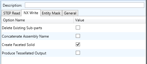
Each of these options is described below:
Option |
Description |
|---|---|
Delete Existing Sub-parts |
Delete existing sub-parts. Default is OFF. Command Line Syntax:
|
Concatenate Assembly Name |
Concatenates assembly name. Default is OFF. Command Line Syntax:
|
Create Faceted Solid |
Creates a faceted solid if the source data is faceted. Default is ON. Command Line Syntax:
|
Produce Tessellated Output |
Create a tessellated JT file instead of an NX file. Default is OFF. Command Line Syntax:
|
STEP to NX Entity Masking Arguments
The image below shows the Masking arguments that are available, with their default settings:
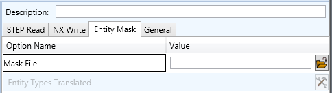
Each of these options is described below:
Option |
Description |
|---|---|
Mask File |
Specifies the Mask File to be written to, that can be referenced by future translations. A Mask file MUST be specified if masking is required. The first line in this file is OFF ALL ENT: Command Line Syntax:
|
Entity Types Translated |
Specifies a selection list (see picture) from which to select which entity types are to be processed. The following types are available: “POI”,”LIN”,”ARC”,”CON”,”CUR”,”SUR”,”FAC”,”SOL” Command Line Syntax:
|
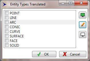
STEP to NX General Arguments
The image below shows the General arguments that are available, with their default settings:
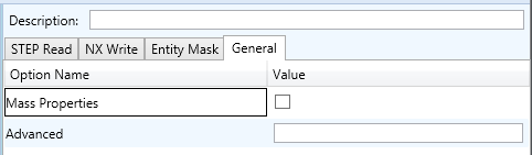
Each of these options is described below:
Option |
Description |
|---|---|
Mass Properties |
Allows Mass Property information to be read from the source data and written as attributes to the PDF document. Default is OFF. Command Line Syntax:
|
Advanced |
Allows any of the Command Line Advanced arguments documented below to be passed to the Unified Interface invocation |
STEP to NX Advanced Arguments
Theorem’s STEP to NX translator has been configured with default settings that optimises the translation process. However, there are times when a satisfactory result cannot be obtained, so it may be required to deploy one or more Advanced Arguments to improve the translated result.
The following table describes useful Advanced Arguments that can be entered into the General Tab -> Advanced field:
Option |
Description |
|---|---|
Parasolid Tolerant Modelling |
Enables Parasolid tolerant modelling. Default is ON Command Line Syntax:
|
Factor |
Specify the factor level of Parasolid Tolerant Modelling when turned on. Default is 3. Command Line Syntax:
|
Sew Parasolid Bodies |
Enables the sewing of Parasolid bodies. Default is ON Command Line Syntax:
|
Tolerance |
Specify the tolerance for the sew command above. Default is 0.01. Command Line Syntax:
|
Keep All Bodies |
A secondary option used with Sew Parasolid Bodies. Keep all bodies (no matter how small) that may be created as a result of sewing. Default is OFF. Command Line Syntax:
|
Incremental Sewing |
Enables incremental sewing when used with Sew Parasolid Bodies. Default is ON. Command Line Syntax:
|
Split Discontinuous Surfaces |
Splits discontinuous surfaces. Default is ON. Command Line Syntax:
|
Force body creation (No check of Parasolid entities) |
Removes the checking of Parasolid entities. Default is ON. Command Line Syntax:
|
Fix Degenerate Edges |
On face create failure, check and fix any degenerate edges. Default is ON. Command Line Syntax:
|
Specify a Face Edge Tolerance |
Specify an edge tolerance to be used when creating faces. Default is ON. Command Line Syntax:
|
Edge Tolerance |
A secondary option used with Specify a Face Edge Tolerance where the tolerance value is assigned. Default is 0.000006. Command Line Syntax:
|
Fix small features in solids |
Remove small edges, sliver and spike faces from solid bodies. Default is OFF. Command Line Syntax:
|
Fix small features in open solids |
Remove small edges, sliver and spike faces from open solids. Default is OFF. Command Line Syntax:
|
Simplify Geometry |
Simplify Geometry. Default is OFF. Command Line Syntax:
|
Attempt Body Healing |
Try to heal a body with issues. Default is ON. Command Line Syntax:
|
Body Healing Tolerance |
A secondary option used with Attempt Body Healing where the tolerance value is assigned. Default is 0.0095. Command Line Syntax:
|
Common Options for NX to STEP
Within the Configuration Manager pane of the Unified Interface, arguments that can be specified when publishing NX data into STEP are grouped into 4 areas:
NX Read – Those arguments that affect how data is read from NX
STEP Write – Those arguments that affect how the data is written to STEP
Entity Mask – Those arguments that allow specific read entities to be masked
General – Those arguments that are common to ALL Publishing activities regardless of source data
NX Read Arguments
The image below shows the NX Read arguments that are available, with their default settings:
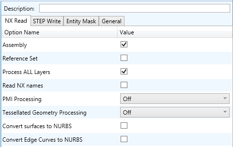
Each of these options is described below.
Option |
Description |
|---|---|
Assembly |
Retain assembly structure. Default is ON. Command Line Syntax:
|
Reference Set |
Enabled reference set processing. Default is OFF Command Line Syntax:
|
Process ALL Layers |
Process all layers, else ‘As Saved’. Default is ON Command Line Syntax:
|
Read NX names |
Read NX entity names, if they exist. Default is OFF. Command Line Syntax:
|
PMI Processing |
Specifies how to process 3D PMI. The options are:
|
Tessellated Geometry Processing |
Enables a tessellated or facetted representation to be used for each Brep solid in the output STEP file. The options are:
|
Convert surfaces to NURBS |
Read surfaces as NURBS surfaces (else read in native form). Default is ON. Command Line Syntax:
|
Convert Edge Curves to NURBS |
Read edge curves as NURBS curves (else read in native format). Default is ON. Command Line Syntax:
|
STEP Write Arguments
The image below shows the STEP Write arguments that are available, with their default settings:
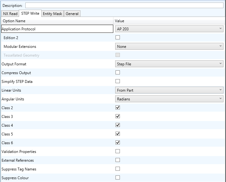
Each of these options is described below:
Option |
Description |
|---|---|
Application Protocol |
Specifies the type of STEP file. Default is AP 203.
Command Line Syntax:
|
Edition 2 |
For AP 203 STEP Files, specifies that edition 2 of the standard is to be used. Default is OFF. Command Line Syntax:
|
Modular Extensions |
Allows modular extensions to be used in AP 203 files. The options are:
|
Tessellated Geometry |
Specifies that tessellated representation is to be used for tessellated/facetted solids in the output AP 242 file. The alternative is to use the older facetted representation. Default is OFF. Command Line Syntax:
|
Output Format |
Specifies the text format of the STEP file. Default is Part 21.
Command Line Syntax:
|
Compress Output |
Specifies that the output STEP file is to be compressed. Default is OFF. Command Line Syntax:
|
Simplify STEP Data |
Any BSpline geometry from the Input file will be checked to see if it can be accurately represented by analytical geometry (e.g. Arcs or spheres). If this is the case, the BSpline geometry will be converted to the appropriate analytical curve or surface, thus reducing the overall size of the resultant STEP File. Default is OFF. Command Line Syntax:
|
Linear Units |
Specifies to units to be used in the output STEP files. CADverter will write the STEP File in identical units of length to those used in the Input file. If different units of length are required (i.e. to send an Inch part from a supplier in the USA, to a European company modelling in Millimetres), then this option allows for the specification of a different unit of length to be used for data written to the STEP File. Command Line Syntax:
|
Angular Units |
By default, the angular units written to a STEP File are Radians. This is the most accurate method for Data Exchange as the majority of CAD Systems use Radians for their internal unit of Angular Measure. If it is required to use a different angular unit then, by applying this option, CADverter will write angular units of the specified type. Command Line Syntax:
|
Class 2 / Class 3 / Class 4 / Class 5 / Class 6 |
This instructs CADverter as to which Conformance Class of data the user wishes to create in the STEP file. For example, the original CAD file may contain solids data, however the user needs it represented in the STEP file as a collection of trimmed surfaces. This would be achieved by selecting Class 4 for output. CADverter will then interpret the data in the context of the specified class. By default, all classes are on, so the resulting STEP File would maintain the data as it appears in the input file. Conformance Classes STEP groups its entities into Conformance Classes 1 to 6. The definitions of the Classes are given below:
Class 1 alone is not supported as it is non-geometric. Command Line Syntax:
|
Validation Properties |
If this option is selected, then the CADverter will write Validation Data (Volume, Surface Area and Centroid information) into the STEP File. Default is OFF. If a suitable STEP post-processor is used to read the STEP File, these values can be used to automatically validate that the exchange has been a success. Command Line Syntax:
|
External References |
CADverter has the capability to create a STEP File containing Structure and PDM information, with references to the Geometry files as either Native CAD models or STEP Files. Default is OFF. This capability is useful for exchanging large structures in multiple files rather than creating a single monolithic STEP File with both Structure and Geometry embedded in it. Command Line Syntax:
|
Suppress Tag Names |
Switches off the processing of TAG names from the STEP File. Some STEP Files contain TAG Names which are duplicates of those applied to other STEP geometric entities (e.g. all Edge Curves may be tagged as “Edge_Curve”). Since most CAD systems require TAG names to be unique, this can lead to extremely long processing times, as each TAG must be altered to avoid name clashes. Default is OFF. Command Line Syntax:
|
Suppress Colour |
Prevents colour being added to the entities in the output STEP file. Default is OFF. Command Line Syntax:
|
NX to STEP Entity Masking Arguments
The image below shows the Masking arguments that are available, with their default settings:
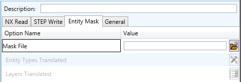
Each of these options is described below:
Option |
Description |
|---|---|
Mask File |
Specifies the Mask File to be written to, that can be referenced by future translations. A Mask file MUST be specified if masking is required. The first line in this file is OFF ALL ENT: Command Line Syntax:
|
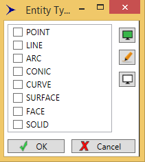
Entity Types Translated |
Specifies a selection list from which to select which entity types are to be processed. The following types are available: “POI”,”LIN”,”ARC”,”CON”,”CUR”,”SUR”,”FAC”,”SOL” Command Line Syntax:
|
Layers Translated |
Specifies a selection list from which to select which layers are to be processed. Command Line Syntax:
|
NX to STEP General Arguments
The image below shows the General arguments that are available, with their default settings:
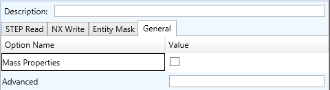
The option is described below:
Option |
Description |
|---|---|
Mass Properties |
This causes CADverter to calculate and print mass properties information for the created solid bodies. The printed output appears in the progress file. This needs to be selected if validation properties are required in the output STEP file. Command Line Syntax:
|
Advanced |
Allows any of the Command Line Advanced arguments documented below to be passed to the Unified Interface invocation |
NX to STEP Advanced Arguments
Theorem’s NX to STEP translator has been configured with default settings that optimises the translation process. However, there are times when a satisfactory result cannot be obtained, so it may be required to deploy one or more Advanced Arguments to improve the translated result.
The following table describes useful Advanced Arguments that can be entered into the General Tab -> Advanced field:
Option |
Description |
|---|---|
pmi_attr |
Adds validation properties for polyline PMI into the STEP file. |
assy_val_props |
Adds validation properties for assembly entities into the STEP file. |
A GUIDE TO THE CM-DATA DEFINITION FILE FOR THEOREM STEP TRANSLATORS
To conform to the published standard, a STEP file must contain some Configuration Management (CM) data and may also contain a geometrical representation of a part or Assembly. Whilst the Theorem translators are supplied to allow the use of STEP AP203, STEP AP214 and STEP AP242 with designed geometry there is a minimum subset of CM data which must be included in the STEP file in order to comply with the standard.
In addition to the minimum subset to satisfy the rules for the AP, there is also a level of support for data within the Units of Functionality (UoF) defined which must be provided to allow the processor to be fully conformant for those UoFs. The minimum level of support implies that the user has a means of defining the data items for those UoFs rather than that the processor will populate them with default values.
This document defines the format of a text file by which this CM data can be supplied to the translator for inclusion with geometry in a STEP part 21 file.
The data required is that which is additional to the geometrical definition and structure and which is necessary to allow the STEP part 21 file created to contain the minimum subset of Configuration Management data in order to satisfy all of the rules of the AP.
Optional input allows the processor to provide full support for the UoFs “identification” and “authorization”.
The remainder of this document deals mainly with the CM Data input for the AP203 CADverter, as the AP214 and AP242 standards do not require the same level of minimum data. For AP214 and AP242, the requirement is only for the Product, Version and Definition data to be present.
This document is divided into sections each of which will give a different perspective on the data to be provided.
The first section provides an overview of the data and file construction.
The second section defines the structure of the file in more detail and describes each entity and attribute. Note that the descriptions given imply a certain interpretation of the AP203 schema and structure and might be described or used differently according to the internal culture and terminology of any enterprise.
The third section defines the mapping to the AP203 schema entities and attributes at AIM (Application Interpreted Model) level.
The fourth section defines the mapping to the AP203 ARM (the Application Reference Model). Not all of the entities and attributes in the file are defined in the ARM but all are required to satisfy the AP203 rules related to the ARM information used.
The fifth section is a sample file as used within the PDES Stepnet testing process.
The sixth section defines the defaults used for each entity where the relevant data is not provided.
1. Overview
The data pertains to a PART and to a specific VERSION and DEFINITION of that PART. The PART must have an owner (the design owner). The VERSION must have been created, supplied, approved and classified. The classification must have an approver. The DEFINITION or the specific design of this version must have a creator and must be approved.
Thus the basis for the data is a series of actions (which includes the required actions of approving other actions). Actions require a “performer” and may have a “date” of action attached.
A “performer” must be defined as a person and the organization to which they belong. Thus the “performer” is defined within the context of a person and organization combination.
A “date” here is defined as the combination of a date and time, the time being specified relative to the appropriate local time zone.
The data is therefore split into 2 sections.
The first section allows basic units of information which might be required more than once within the part related data to be defined. These are organizations, people and time zones. This is referred to as the library section below.
The second section allows the specific part information to be supplied and uses the data from the first section.
2. Structure and Mapping
The data is differentiated into header records and attribute records. Header records begin with a # and define the start of a block of attribute information. The block name defines the type of data following and is in upper case characters (eg #ORG, #PERSON, #CLASSIFICATION).
Attribute records begin with a $ which is followed by the attribute name in lower case characters. This name is followed by a colon which is then followed by the data. The data may contain blank characters. Where multiple items are data are defined (eg $date) the items are delimited by a comma
e.g. $person_id : Person-1 $purpose : Because I want to $date : edt,1993,7,17,13,45,20
The majority of the information defined is textual. Where it is other than text data this is specified in the description for the attribute in this section.
Where AP203 restrictions apply the relevant possible list of options is given. If the data is text information in AP203 then the user may choose to use an alternative value and no check is made that the restriction rule has been satisfied. NB for make_or_buy the data within the AP203 schema is defined with an enumeration and so only the values listed may be used.
Where appropriate, recommendations from the AP203 Recommended Practices document have been given.
The base information for the CM data consists of people, organizations, addresses and date- times.
The format allows for the input of a number of organizations, each one initiated via the #ORG record and for which a unique $org_id must be provided.
Where people are referred to this is done within the context of an organization so the organizations are defined first. Subsequently each person block is defined with a reference via org_id back to the relevant organization.
The persons are initiated via a #PERSON record for which a $org_id record must be used to identify the relevant organization and also for which a unique $person_id record must be provided which identifies the person and organization combination.
Date and time items are defined within the context of a time zone so the time zone(s) data is defined first. For each time zone, initiated with a #TIME_ZONE record, a unique name must be defined. Time zone descriptions below are done in relation to Greenwich Meant Time (GMT). For the purposes of this data GMT is deemed to be equivalent to Coordinated Universal Time which is the formal reference time for AP203.
Persons and organizations may have addresses. Addresses must be defined with an address_id before they can be referred to within a person or org definition. They are linked via the address_id.
Following the input of the base information the data relevant to the specific product may be defined. The #DATA record delineates between organization, person and time_zone data and the product data.
Each set of data for the product may refer back to persons via the person_id. Date items refer to the relevant time zone via the given name.
Each item used in this file is flagged as mandatory (m) or optional (o). Note that in most cases the omission of a mandatory attribute will cause an error message to be given but a default value will be assigned to the attribute to allow processing to continue.
The library section of the file contains #ORG, #PERSON and #TIMEZONE blocks.
Mandatory/Optional |
Field |
Description |
|---|---|---|
m |
$address_id |
address identifier |
o |
$internal_location |
|
o |
$street_number |
|
o |
$street |
|
o |
$postal_box |
|
o |
$town |
|
o |
$region |
|
o |
$postal_code |
|
o |
$country |
|
o |
$facsimile_number |
|
o |
$telephone_number |
|
o |
$electronic_mail_address |
|
o |
$telex_number |
NB! at least one optional parameter must be set
Mandatory/Optional |
Field |
Description |
|---|---|---|
m |
$org_id |
unique organization identifier |
m |
$org_name |
the name of the organization |
o |
$org_description |
a description of the organization |
o |
$address_id |
organization address identifier |
Mandatory/Optional |
Field |
Description |
|---|---|---|
m |
$org_id |
the organization to which the person belongs in this context |
m |
$person_id |
unique person id |
m |
$first_name |
person’s first name |
m |
$last_name |
person’s last name |
o |
$middle |
person’s middle names if any exist |
o |
$prefix |
person’s prefix titles if any exist |
o |
$suffix |
person’s suffix titles if any exist |
o |
$address_id |
person address identifier |
Mandatory/Optional |
Field |
Description |
|---|---|---|
m |
$name&offset |
The time zone in which the activity dates are defined is specified relative to GMT. A name for the time zone by which the dates provided will refer to it is given together with the hours difference from GMT. Positive hour offset values apply to time zones which are ahead (ie east) of the meridian. Negative time zones refer to time zones which are behind the meridian (ie west of the meridian). Optionally a minute offset can be added. Format is: name,hour or name,hour,minute name – may not contain commas. hour – is an integer number. minute – is an integer number. |
The end of the library section and start of the data section is defined with a block header #DATA
When dates are defined in this section it is actually a date and time which has to be provided. The syntax for a date record is as follows.
$date : time-zone-name,year,month,day,hour,minute,second
Mandatory/Optional |
Field |
Description |
|---|---|---|
m |
time-zone-name |
name of the time zone defined in the library section |
m |
year |
the year (integer number) |
m |
month |
the month of the year (integer number) |
m |
day |
the day of the month (integer number) |
m |
hour |
the hour of the day (integer number) |
o |
minute |
the minute of the hour (integer number) |
o |
second |
the second of the minute (real number) |
Each field is delimited with a comma.
The data in this section can be considered in 3 categories:
Information about the part
Information about version of the part
Information about definition of the part
The data section can specify information related to the part via the following block headers grouped according to these 3 categories:
#PRODUCT
#DESIGN_OWNER
#PRODUCT_VERSION
#PRODUCT_SOURCE
#DESIGN_SUPPLIER
#VERSION_CREATION
#VERSION_APPROVAL
#CLASSIFICATION
#CLASSIFICATION_APPROVAL
#PRODUCT_DEFINITION
#DESIGN_CREATOR
#PRODUCT_APPROVAL
Definitions and attributes for these are as follows:
Mandatory/Optional |
Field |
Description |
|---|---|---|
m |
$product_name |
part name |
m |
$product_id |
part number |
o |
$description |
part description |
o |
$product_type |
part_type be assembly, inseparable_assembly, detail or customer_furnished_equipment |
o |
$product_class |
part_classification must be assembly, inseparable_assembly, detail, customer_furnished_equipment cast, coined, drawn, extruded, forged, formed, machined, molded, rolled or sheared |
o |
$context_name |
name for product_context (AP203 mechanical_context) |
o |
$category_name |
optional additional product category. Products may have additional category information. Each category may have a description. The additional category will be related to the product with a product_category_relationship which may have a name and description. A category name introduces a new category definition. Subsequent category information will pertain to that category until another category name is found. Note for standard part indicator set as standard_part |
o |
$category_desc |
product_category.description for preceding category |
o |
$category_rel_name |
product_category_relationship name for preceding category linking to product_related_product_category |
o |
$category_rel_desc |
product_category_relationship.description for preceding category_rel |
Mandatory/Optional |
Field |
Description |
|---|---|---|
m |
$person_id |
the id of the person defined in the library section |
Mandatory/Optional |
Field |
Description |
|---|---|---|
m |
$version |
the revision letter |
o |
$description |
a description for this version |
Mandatory/Optional |
Field |
Description |
|---|---|---|
m |
$make_or_buy |
may be MADE, BOUGHT or NOT_KNOWN |
Mandatory/Optional |
Field |
Description |
|---|---|---|
m |
$person_id |
the id of the person defined in the library section |
Mandatory/Optional |
Field |
Description |
|---|---|---|
m |
$person_id |
the id of the person defined in the library section |
Mandatory/Optional |
Field |
Description |
|---|---|---|
m |
$person_id |
the approver |
m |
$status |
status of the approval must be one of: Approved, not_yet_approved, disapproved, withdrawn |
m |
$purpose |
the purpose of the action |
m |
$date |
the date when the action took place |
Mandatory/Optional |
Field |
Description |
|---|---|---|
m |
$person_id |
the classification officer |
m |
$status |
the classification level must be one of: unclassified, classified, proprietary, confidential, secret, top_secret |
m |
$purpose |
the purpose of the classification |
m |
$name |
the name for the classification if the version is defined with a status of classified, this could be the company name for the classification eg “secret restricted” |
m |
$date |
the date of classification |
Mandatory/Optional |
Field |
Description |
|---|---|---|
m |
$person_id |
the approver |
m |
$status |
status of the approval must be one of: approved, not_yet_approved, disapproved, withdrawn |
m |
$purpose |
the purpose of the action |
m |
$date |
the date when the action took place |
Mandatory/Optional |
Field |
Description |
|---|---|---|
m |
$description |
a description for this definition |
o |
$id |
identifier for product_definition |
o |
$life_cycle_stage |
for AP203 must be set as design |
o |
$context_name |
design discipline context name |
o |
$shape_name |
name for product definition shape |
o |
$shape_description |
description for product definition shape |
Mandatory/Optional |
Field |
Description |
|---|---|---|
m |
$person_id |
the id of the person defined in the library section |
m |
$date |
the date when the design creation took place |
Mandatory/Optional |
Field |
Description |
|---|---|---|
m |
$person_id |
the approver |
m |
$status |
status of the approval must be one of: approved, not_yet_approved, disapproved, withdrawn |
m |
$purpose |
the purpose of the action |
m |
$date |
the date when the action took place |
The file is terminated with an #END record
3. Mappings to the AIM (The Schema)
Mandatory/Optional |
Field |
AIM Mapping |
|---|---|---|
m |
$org_id |
organization.id |
m |
$org_name |
organization.name |
o |
$org_description |
organization.description |
Mandatory/Optional |
Field |
AIM Mapping |
|---|---|---|
m |
$org_id |
$organization.id : person_and_organization |
m |
$person_id |
person.id |
m |
$first_name |
person.first_name |
m |
$last_name |
person.last_name |
o |
$middle |
person.middle_names |
o |
$prefix |
person.prefix_titles |
o |
$suffix |
person.suffix_titles |
Mandatory/Optional |
Field |
AIM Mapping |
|---|---|---|
o |
$internal_location |
address.internal_location |
o |
$street_number |
address.street_number |
o |
$street |
address.street |
o |
$postal_box |
address.postal_box |
o |
$town |
address.town |
o |
$region |
address.region |
o |
$postal_code |
address.postal_code |
o |
$country |
address.country |
o |
$facsimile_number |
address.facsimile_number |
o |
$telephone_number |
address.telephone_number |
o |
$electronic_mail_address |
address.electronic_mail_address |
o |
$telex_number |
address.telex_number |
NB! at least one optional parameter must be set
Mandatory/Optional |
Field |
AIM Mapping |
|---|---|---|
m |
$name&offset |
file-id-name,hour,minute – file-id-name is the name used within this file |
m |
(hour) |
coordinated_universal_time_offset.hour_offset. The sign of this value defines ahead_or_behind. +ve values -> ahead. -ve values -> behind (so Eastern Standard Time = -5) |
o |
(minute) |
coordinated_universal_time_offset.minute_offset |
Where for any date below:
Mandatory/Optional |
Field |
AIM Mapping |
|---|---|---|
m |
file-id-name,year,month,day,hour,minute,second |
date |
m |
file-id-name |
-> time_zone -> coordinated_universal_time_offset |
m |
year |
calendar_date.year_component |
m |
month |
calendar_date.month_component |
m |
day |
calendar_date.day_component |
m |
hour |
local_time.hour_component |
o |
minute |
local_time.minute_component |
o |
second |
local_time.second_component |
#DATA
Mandatory/Optional |
Field |
AIM Mapping |
|---|---|---|
m |
$product_name |
product.name |
m |
$product_id |
product.id |
o |
$description |
product.description |
o |
$product_type |
product_related_product_category.name must be: Assembly, inseparable_assembly, detail, customer_furnished_equipment |
o |
$product_class |
product_related_product_category.name must be one of: product_type list, cast, coined, drawn, extruded, forged, formed, machined, molded, rolled or sheared |
o |
$context_name |
product_context.name (AP203 mechanical_context.name) |
o |
$category_name |
product_category.name. Note for standard part indicator set as standard_part |
o |
$category_desc |
product_category.description for preceding category |
o |
$category_rel_name |
product_category_relationship.name |
o |
$category_rel_desc |
product_category_relationship.description |
Mandatory/Optional |
Field |
AIM Mapping |
|---|---|---|
m |
$person_id |
cc_design_person_and_organization_assignment.assigned_person_and_organization where: cc_design_person_and_organization_assignment.role -> person_and_organization_role.name = “design_owner” cc_design_person_and_organization_assignment.items[0] = product |
Mandatory/Optional |
Field |
AIM Mapping |
|---|---|---|
m |
$version |
product_definition_formation_with_specified_source.id |
o |
$description |
product_definition_formation_with_specified_source.description |
Mandatory/Optional |
Field |
AIM Mapping |
|---|---|---|
m |
$make_or_buy |
product_definition_formation_with_specified_source.make_or_buy NB must be BOUGHT, MADE or NOT_KNOWN |
Mandatory/Optional |
Field |
AIM Mapping |
|---|---|---|
m |
$person_id |
cc_design_person_and_organization_assignment.assigned_person_and_organization where: cc_design_person_and_organization_assignment.role -> person_and_organization_role.name = “design_supplier” cc_design_person_and_organization_assignment.items[0] = product_definition_formation_with_specified_source |
Mandatory/Optional |
Field |
AIM Mapping |
|---|---|---|
m |
$person_id |
cc_design_person_and_organization_assignment.assigned_person_and_organization where: cc_design_person_and_organization_assignment.role -> person_and_organization_role.name = “creator” cc_design_person_and_organization_assignment.items[0] = product_definition_formation_with_specified_source |
Mandatory/Optional |
Field |
AIM Mapping |
|---|---|---|
m |
$person_id |
approval_person_organization.person_organization |
m |
$status |
approval_status.name |
m |
$purpose |
approval.level |
m |
$date |
approval_date_time.date_time and cc_design_date_and_time_assignment.assigned_date_and_time where: cc_design_date_and_time_assignment.role -> date_time_role.name = “sign_off_date” cc_design_date_and_time_assignment.items[0] = approval_person_organization for VERSION_APPROVAL |
Mandatory/Optional |
Field |
AIM Mapping |
|---|---|---|
m |
$person_id |
cc_design_person_and_organization_assignment.assigned_person_and_organization where: cc_design_person_and_organization_assignment.role -> person_and_organization_role.name = “classification_officer” cc_design_person_and_organization_assignment.items[0] = security_classification |
m |
$status |
security_classification_level.name |
m |
$purpose |
security_classification.purpose |
m |
$name |
security_classification.name |
m |
$date |
cc_design_date_and_time_assignment.assigned_date_and_time where: cc_design_date_and_time_assignment.role -> date_time_role.name = “classification_date” .items[0] = security_classification |
Mandatory/Optional |
Field |
AIM Mapping |
|---|---|---|
m |
$person_id |
approval_person_organization.person_organization |
m |
$status |
approval_status.name |
m |
$purpose |
approval.level |
m |
$date |
approval_date_time.date_time and cc_design_date_and_time_assignment.assigned_date_and_time where: cc_design_date_and_time_assignment.role -> date_time_role.name = “sign_off_date” cc_design_date_and_time_assignment.items[0] = approval_person_organization for CLASSIFICATION_APPROVAL |
Mandatory/Optional |
Field |
AIM Mapping |
|---|---|---|
m |
$description |
product_definition.description |
o |
$id |
product_definition.id |
o |
$life_cycle_stage |
product_definition_context.life_cycle_stage using product_definition_context subtype design_context |
o |
$context_name |
product_definition_context.name |
o |
$shape_name |
product definition shape.name |
o |
$shape_description |
product definition shape.description |
Mandatory/Optional |
Field |
AIM Mapping |
|---|---|---|
m |
$person_id |
cc_design_person_and_organization_assignment.assigned_person_and_organization where: cc_design_person_and_organization_assignment.role -> person_and_organization_role.name = “creator” cc_design_person_and_organization_assignment.items[0] = product_definition |
m |
$date |
cc_design_date_and_time_assignment.assigned_date_and_time where: cc_design_date_and_time_assignment.role -> date_time_role.name = “creation_date” cc_design_date_and_time_assignment.items[0] = product_definition |
Mandatory/Optional |
Field |
AIM Mapping |
|---|---|---|
m |
$person_id |
approval_person_organization.person_organization |
m |
$status |
approval_status.name |
m |
$purpose |
approval.level |
m |
$date |
approval_date_time.date_time and cc_design_date_and_time_assignment.assigned_date_and_time where: cc_design_date_and_time_assignment.role -> date_time_role.name = “sign_off_date” cc_design_date_and_time_assignment.items[0] = approval_person_organization for PRODUCT_APPROVAL |
#END
4. Mappings to the ARM
Note that there are many attributes which don’t map directly to the ARM of AP203 but need to be defined to satisfy the entity definitions or AP203 rules based on other ARM requirements.
Only those elements of the file format definition which relate directly to the ARM are listed here.
The data is indented in order to denote a dependency on a previous block. eg DESIGN_OWNER is dependent on PRODUCT, CLASSIFICATION_APPROVAL is dependent on CLASSIFICATION.
ARM mappings are as follows.
Mandatory/Optional |
Field |
ARM Mapping |
|---|---|---|
#ORG |
PERSON_ORGANIZATION.organization |
|
#PERSON |
PERSON_ORGANIZATION.person |
|
m |
$org_id |
|
m |
$person_id |
PERSON_ORGANIZATION.person_organization_id |
#ADDRESS |
Address |
Mandatory/Optional |
Field |
ARM Mapping |
|---|---|---|
m |
$product_name |
PART.part_nomenclature |
m |
$product_id |
PART.part_number |
o |
$product_type |
PART_TYPE |
o |
$product_class |
PART_CLASSIFICATION |
o |
$category_name |
Standard part indicator = ‘standard_part’ |
Mandatory/Optional |
Field |
ARM Mapping |
|---|---|---|
m |
$person_id |
PERSON_ORGANIZATION (Is The Owner Of PART) |
Mandatory/Optional |
Field |
ARM Mapping |
|---|---|---|
m |
$version |
PART_VERSION.revision_letter |
#PRODUCT_SOURCE |
PART_VERSION.make_or_buy_code |
Mandatory/Optional |
Field |
ARM Mapping |
|---|---|---|
m |
$person_id |
PERSON_ORGANIZATION (Missing From ARM) |
Mandatory/Optional |
Field |
ARM Mapping |
|---|---|---|
m |
$person_id |
PERSON_ORGANIZATION (Is The Creator Of PART_VERSION) |
Mandatory/Optional |
Field |
ARM Mapping |
|---|---|---|
m |
$person_id |
PERSON_ORGANIZATION (APPROVAL is Authorized By… Approves PART_VERSION) |
m |
$status |
APPROVAL.status |
m |
$purpose |
APPROVAL.purpose |
m |
$date |
APPROVAL.date |
Mandatory/Optional |
Field |
ARM Mapping |
|---|---|---|
m |
$person_id |
PERSON_ORGANIZATION (Classification Officer) |
m |
$status |
PART_VERSION.security_code |
Mandatory/Optional |
Field |
ARM Mapping |
|---|---|---|
m |
$person_id |
PERSON_ORGANIZATION (CLASSIFICATION is approved by) |
Mandatory/Optional |
Field |
ARM Mapping |
|---|---|---|
m |
$description |
DESIGN_DISCIPLINE_PRODUCT_DEFINITION.description |
o |
$life_cycle_stage |
discipline_id life cycle stage |
o |
$context_name |
discipline_id name |
Mandatory/Optional |
Field |
ARM Mapping |
|---|---|---|
m |
$person_id |
PERSON_ORGANIZATION (Is The Creator Of DESIGN_DISCIPLINE_PRODUCT_DEFINITION) |
m |
$date |
DESIGN_DISCIPLINE_PRODUCT_DEFINITION.creation_date |
Mandatory/Optional |
Field |
ARM Mapping |
|---|---|---|
m |
$person_id |
PERSON_ORGANIZATION (APPROVAL is Authorized By… Approves DESIGN_DISCIPLINE_PRODUCT_DEFINITION) |
5. Sample File
In this sample file empty records have been used to provide easier reading but the blank lines are not required for an actual file and would be ignored.
#ADDRESS
$address_id : NVI-Address
$region : Michigan
$country : USA

#ADDRESS
$address_id : White-Address
$town : Detroit
$country : USA
$electronic_mail_address : KWhite@NVI.com

#ORG
$org_id : NVI-Michigan
$org_name : New Ventures, Inc.
$address_id : NVI-Address

#ORG
$org_id : CDI
$org_name : Contract Design, Inc

#PERSON
$org_id : NVI-Michigan
$person_id : 333-003
$last_name : White
$first_name : K.
$middle : H.
$address_id : White-Address

#PERSON
$org_id : NVI-Michigan
$person_id : 555-005
$last_name : Johnson
$first_name : Stephen
$prefix : Mr.

#PERSON
$org_id : NVI-Michigan
$person_id : 666-006
$last_name : Spock
$first_name : Robert
$middle : S.

#PERSON
$org_id : NVI-Michigan
$person_id : 222-002
$last_name : Pierre
$first_name : Gabrielle

#PERSON
$org_id : NVI-Michigan
$person_id : 777-007
$last_name : Black
$first_name : James

#PERSON
$org_id : CDI
$person_id : CDI-2
$last_name : Smith
$first_name : B.

#TIME_ZONE
$name&offset : edt -5

#DATA

#PRODUCT
$product_name : Fillet Boot
$product_id : 22222

#PRODUCT_VERSION
$version : A

#PRODUCT_SOURCE
$make_or_buy : BOUGHT

#DESIGN_OWNER
$person_id : 333-003

#DESIGN_SUPPLIER
$person_id : CDI-2

#DESIGN_CREATOR
$person_id : 222-002
$date : edt,1993,7,19,19,46,55

#VERSION_CREATION
$person_id : 222-002

#PRODUCT_DEFINITION
$description : detailed drawing as planned for STEP conformance testing

#VERSION_APPROVAL
$person_id : 777-007
$status : approved
$purpose : Approved as initial STEP test case part
$date : edt,1993,7,17,13,29,52

#PRODUCT_APPROVAL
$person_id : 777-007
$status : approved
$purpose : Approved as STEP conformance testing drawing
$date : edt,1993,7,19,19,47,51

#CLASSIFICATION_APPROVAL
$person_id : 666-006
$status : approved
$purpose : Approved as unclassified STEP test data
$date : edt,1993,7,17,13,47,28

#CLASSIFICATION
$person_id : 555-005
$status : unclassified
$purpose : open availability of STEP test data
$date : edt,1993,7,17,13,45,20
$name : 1993-C1

#END
6. Defaults Definition
This describes the full set of defaults used for the data attributes which may be defined. However, once an organization has been defined then that organization becomes the default. Once a person has been defined then that person becomes the default person (and organization).
Any unset date will be defaulted to the current time and date, defined as YYYY,MM,DD,HH below
#ORG
$org_id : Default_oid
$org_name : Default_org

#PERSON
$org_id : Default_oid
$person_id : Default_pid
$last_name : Doe
$first_name : John

#TIME_ZONE
$name&offset : tsc_gmt,0

#DATA

#PRODUCT
$product_name : product name
$product_id : product id
$product_type : detail or assembly dependent on data

#PRODUCT_VERSION
$version : version 0

#PRODUCT_SOURCE
$make_or_buy : NOT_KNOWN

#DESIGN_OWNER
$person_id : Default_pid

#DESIGN_SUPPLIER
$person_id : Default_pid

#DESIGN_CREATOR
$person_id : Default_pid
$date : tsc_gmt,YYYY,MM,DD,HH

#VERSION_CREATION
$person_id : Default_pid

#PRODUCT_DEFINITION
$description : unknown

#VERSION_APPROVAL
$person_id : Default_pid
$status : not_yet_approved
$purpose : unknown
$date : tsc_gmt,YYYY,MM,DD,HH

#PRODUCT_APPROVAL
$person_id : Default_pid
$status : not_yet_approved
$purpose : unknown
$date : tsc_gmt,YYYY,MM,DD,HH

#CLASSIFICATION_APPROVAL
$person_id : Default_pid
$status : not_yet_approved
$purpose : unknown
$date : tsc_gmt,YYYY,MM,DD,HH

#CLASSIFICATION
$person_id : Default_pid
$status : unclassified
$purpose : unknown
$date : tsc_gmt,YYYY,MM,DD,HH

#END