User Guide
Translating Interactively from within 3DExperience
Launching 3DExperience with Theorem Plug-ins
The 3DExperience to Creo View translator allows an opened 3DExperience part or assembly to be exported directly to Creo View.
In order to translate from within 3DExperience, the application must be started using a Theorem environment, so that the appropriate Theorem partner plug-ins are available. (See 3DExperience Environment files)
3DExperience can be started from a desktop shortcut created during installation.
Alternatively, it can be started via the script provided in the translator installation located in:
<installation_directory>bin
The script name is:
start_3DEXPERIENCE_Theorem_Multi-CAD_CREOVIEW_CATIAV6R<version>.cmd
(where <version> should be substituted for the version of 3DExperience that you have installed - e.g. 2021x, 2022x, 2023x)
Interactive Export to Creo View
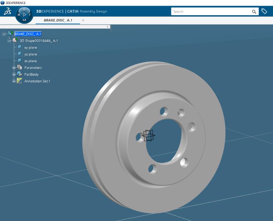
Once the 3DExperience application has been launched, open the product or representation that is going to be exported to Creo View.
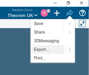
Select the arrow in the top right corner, then from the list displayed select Export.
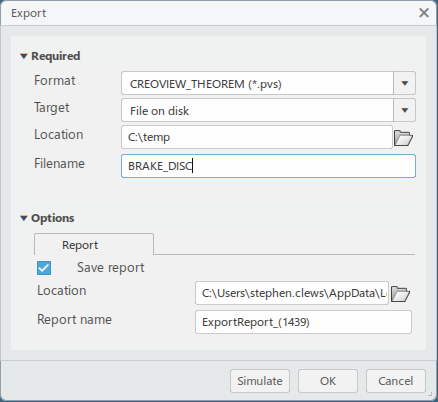
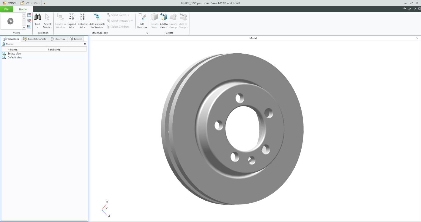
In the Export dialog box is displayed. Ensure the “Format” is set to CREOVIEW_THEOREM (*.pvs). Select the required location for the files and ensure the Filename displayed is correct. Click OK to initiate the translation.
Theorem Interactive Conversion Settings
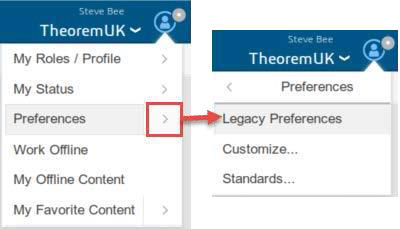
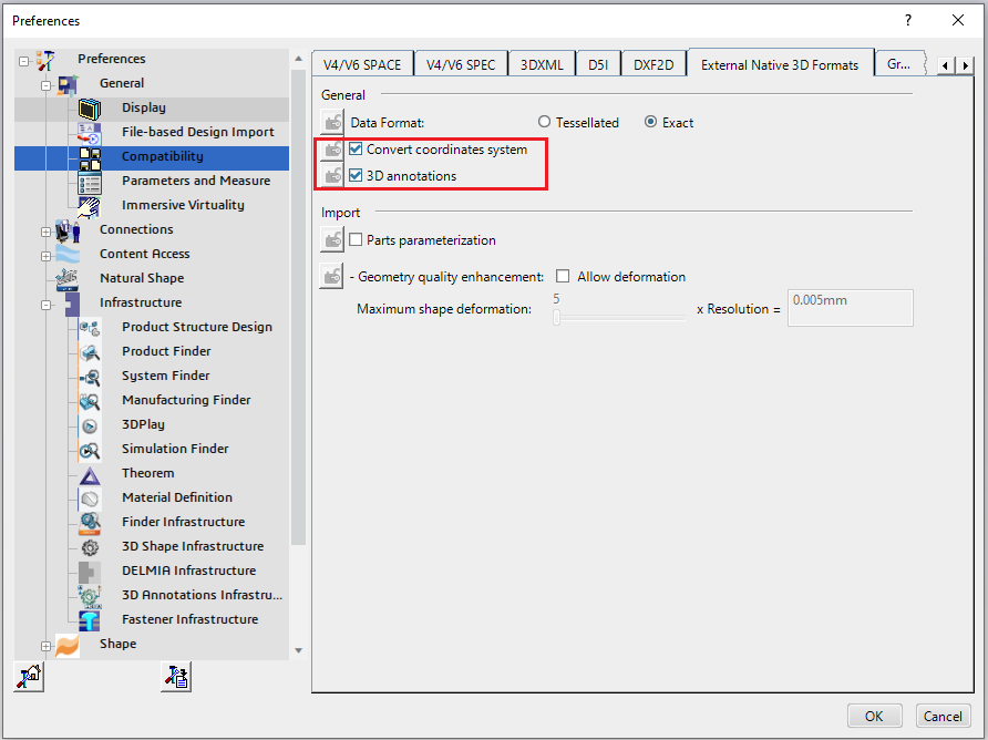
The 3DExperience interface does not currently require the user to apply any specific settings for the translation. There are some general settings that should be checked if required (e.g. for PMI conversion.) These are accessed through Preferences>Legacy Preferences>General>Compatibility>External Native 3D Formats. There are also some options that can be applied within the Theorem setting. These are accessed through Preferences>Legacy Preferences> Infrastructure>Theorem:
This page is a standard Dassault Page that sets the preferred mode of conversion (in this case Exact), and also the general options “Convert coordinates system” and “3D annotations”. Both of which are toggled on.
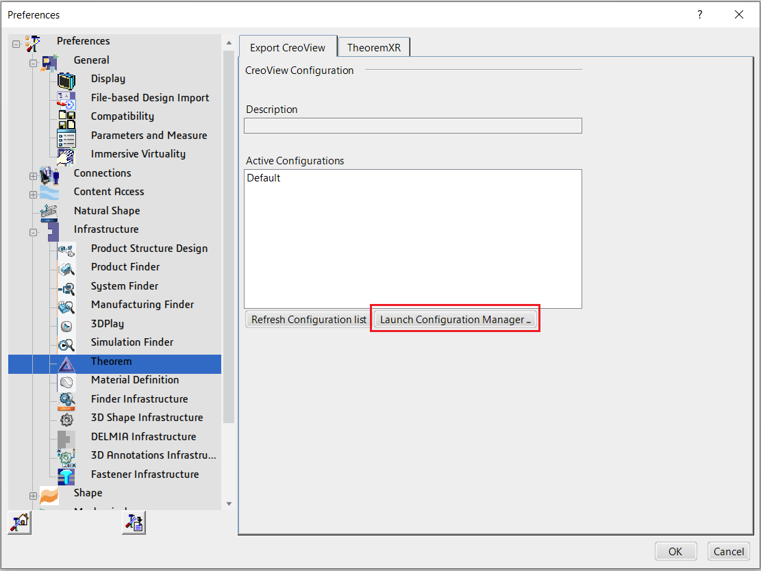
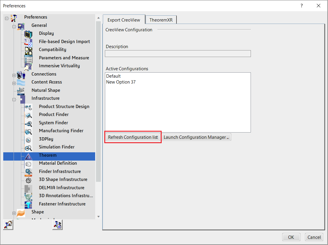
A dedicated tab under ‘Infrastructure>Theorem’ allow the user access to Theorem Configurations for Publish 3D. From this Panel, the user can select a predefined configuration or create a new configuration. To create a new configuration, select the ‘Launch Configuration Manager’ command.
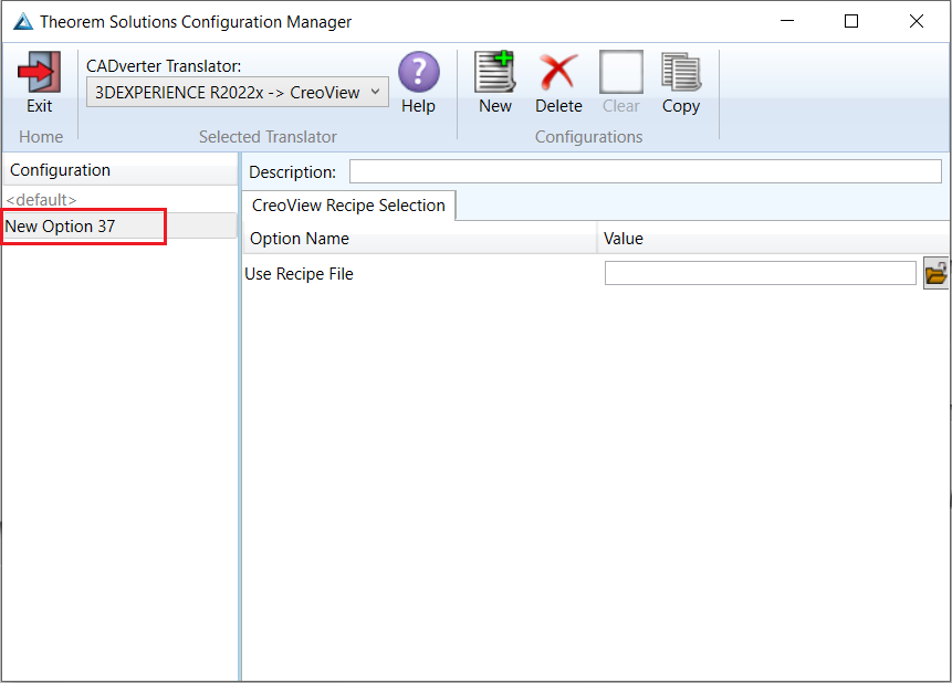
In the configuration manager window, select New. Rename as required.
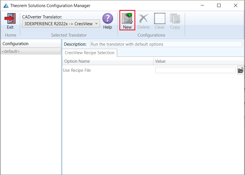
Any new configurations created will be displayed in the Active Configurations list once it has been refreshed. To do this select ‘Refresh Configuration list’
Configuration Manager
Within the Configuration Manager, only a CreoView Recipe Selection tab is available where a saved recipe file (.rcp) can be added.
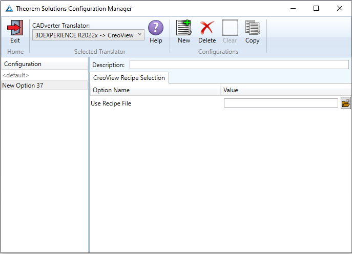
To add a recipe file, click on the folder icon and navigate to the directory where the file is saved. Select the file then click Open to add it to the configuration selected in the configuration manager.
Recipe Files
A recipe is a set of user-defined rules that drive the individual CAD Adapter. The recipe concept provides a solution to the problem of efficiently converting CAD data into a form suitable for viewing on a wide range of computer platforms. While most CAD parts will convert into an efficient form for large-scale visualisation, some parts require modifications to the standard visualisation recipe to be viewed effectively.
The Adapter is provided with a master or default recipe file. This file is preconfigured to allow the visualisation of most objects. The master recipe file should not be edited. Instead, new recipe files can be created using the Save As function in the recipe editor (rcpedit.exe) provided with the translator. Launching the rcpedit.exe will display a number of tabs with the available translation options displayed under these tabs.
The Basic tab provides standard PTC options that we will not discuss in this document, as these are well documented in PTC’s ‘Creo View MCAD Adapters Installation and Configuration Guide’ document, which can be obtained via the PTC Reference Documents Site at https://www.ptc.com/appserver/cs/doc/refdoc.jsp.
Instead, we will focus on the Theorem specific settings that affect the output. These are accessible via the Advanced Tab and are grouped into 2 sub pages:
CATIAV6
CREO VIEW
CATIAV6
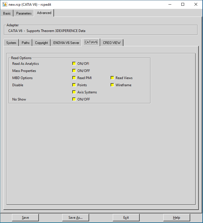
Each of the options displayed in the image above are described below:
Read Options |
Description |
|---|---|
Read as Analytics |
If checked this causes the data to be read as Analytic data where possible. |
Mass Properties |
Reads the Mass properties from the CAD data where available. |
MBD Options |
When checked reads PMI and Views/Capture data if available. Note this is only available with an add on license. |
Disable |
Stops Points, Wire Frame and/or Axis systems from being read. |
No Show |
Read’s data that has been hidden. |
CREO VIEW
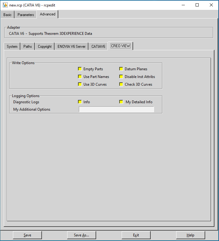
Each of the options displayed in the image above are described below:
Write Options |
Description |
|---|---|
Empty Parts |
Creates an empty (contains a single point at X0, Y0, Z0) dummy .ol file for empty nodes, to force the geometry node creation, where no geometry exists. |
Datum Planes |
Allows large planes, that are by default omitted, to be written as Datum Planes. Selecting this option will replace PLANES where the bounding box diagonal exceeds 0.1Km with a Datum PLANE 35mm square. The bounding box size can be adjusted using: The size of the created datum PLANE can be adjusted using:
|
Use Part Names |
Use the ‘Part Number’ names for assembly nodes. The default is to use ‘Instance Names’. |
Disable Inst Attribs |
Disables the output of any Instance attributes. |
Use 3D Curves |
This option allows the Creo View API to generate its own 2D curves. This option is most likely only ever used as a work around when poor data is encountered. |
Check 3D Curves |
This option allows the Adapter to test the data and if necessary automatically enable
Use 3D Curves. A default tolerance of 0.01 (1%) face/surface overlap being used for
these checks. This tolerance can be adjusted with |
Logging Options |
|
|---|---|
Info |
Generate a more verbose log. |
My Detailed Info |
Generate a more verbose log. Used as a diagnostics level of detail in the log file (for debug purposes only). |
My Additional Options |
|
|---|---|
set_omit_large_planes <value> |
Omit large PLANEs greater than the tolerance value (default is 100 M). e.g. |
set_create_datum_planes <value> |
Omit large PLANEs greater than the tolerance value (default is 100 M). Omitted large PLANEs can be replaced by datum PLANEs (default 35mm). The size of that datum PLANE is controlled with this option. e.g. |
Translating in Batch using CATUtil - DataExchangePLMBatch
Launching DataExchangePLMBatch
The Dassault Systemes CATUTIL Batch Monitor tool can be launched with the correct Theorem enabled environment using the scripts provided in the Translator installation at:
<installation_directory>\bin\start_CATUTIL_Theorem_Multi-CAD_CREOVIEW_CATIAV6R<revision>.cmd
(where <revision> should be substituted for the version of 3DExperience that you have installed - e.g. 2021x, 2022x, 2023x)
It can also be started from the Tools>Utility workbench within an Interactive 3DExperience session.

Batch Export to Creo View
Here is an example showing what is required in preparation for a 3DExperience database selection and batch export.
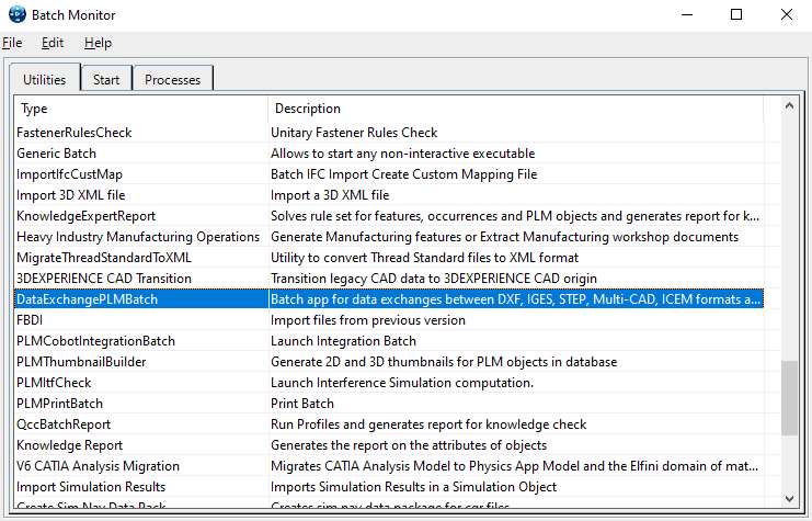
Double click on DataExchangePLMBatch.
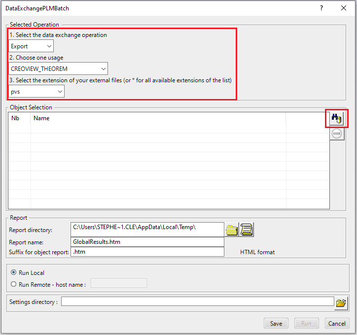
Ensure that ‘Export’ is selected as the data exchange operation, ‘CREOVIEW_THEOREM’ is selected as the usage and ‘pvs’ is selected as the extension.
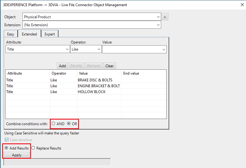
To add the required products for the batch export, select the 3DExperience Platform Object Search icon.
In the subsequent window displayed, add the required products using the correct attribute, operator and value ensuring that the correct object type has been selected. (E.g. Physical Product.) For multiple products ensure that the OR condition has been selected. Select Add results and click Apply to add the list of products to the Object Selection field.
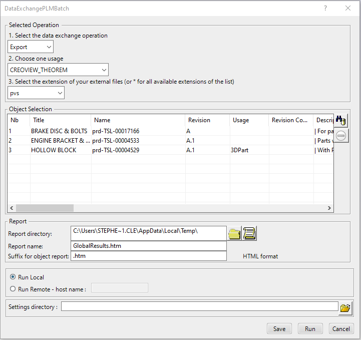
To change the location where both the report and the pvs files will be saved, select the icon next to the Report directory field, then select the required directory.
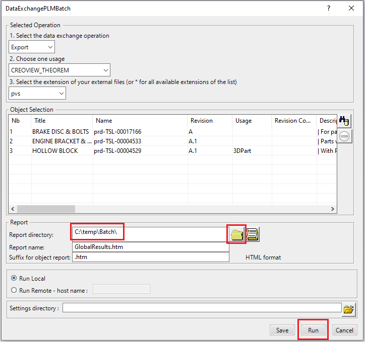
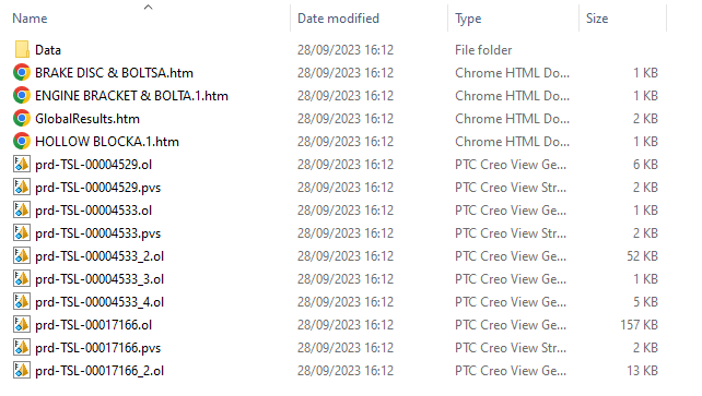
Click Run to initiate the Batch Export.
Adding Options for a Batch Translation
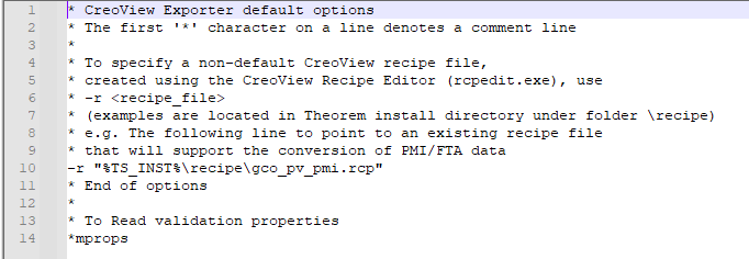
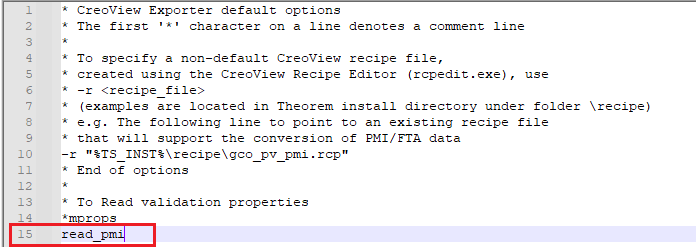
Options displayed in the recipe editor (rcpedit.exe) can be added to the xcad_creoview_opts.txt file available in the following location when translating via batch.
<installation_directory>\data\CreoView
To include a new option in a batch translation, simply enter the name of the argument to a new line in the xcad_creoview_opts.txt file. In the example below the read_pmi argument has been added.
Translating on the Command Line
It is possible to run a 3DExperience to Creo View translation on the command line, however as all CAD data is saved in the 3DExperience database an XML file will need to be used as the input file instead of a CAD file. This XML file contains all the necessary information to locate, open and translate the CAD data. This is explained in more detail below. In order to run a translation on the command line the following inputs are required:
<TS_INST>\bin\catia6r<revision>_pv.cmd <input_file> -p <output_path> -o <output_file> -r <recipe_file>
Where: <TS_INST> is the Theorem Solutions software installation directory.
Where: <revision> is the version of 3DExperience that you have installed - e.g. 2021x, 2022x, 2023x.
<input_file>
Is an xml file defining access to a specific object in the 3DExperience database.
This file provides user login details (V6R2013x) or a Login Ticket (2015x onwards) (see JT Configuration File), to a specified Enovia repository plus a set of 3 attribute names and values which will uniquely identify the input object required for the conversion. Examples of the input file XML can be found in the <TS_INST>\samples\3dexperience folder. These can be modified and saved on your local drive.
Here is an example of the xml input file for 3DExperience:
<?xml version="1.0" encoding="utf-8"?>
<mc6_read>
  <!-- parameters must be in this ORDER -->
  <!-- parameters only the value passed to V6  -->
  <parameters>
    <attribute name="repository" value="PLM1"/>
    <attribute name="ServerName" value="3dspace.theorem.com"/>
    <attribute name="ServerPort" value="447"/>
    <attribute name="ServerRootURI" value="3dspace"/>
    <attribute name="LoginTicket"
      value="REEyNzM3M0Q1REM2NDgxQzlFNzk1QzIwNjZGRDYzODN8Um9iaW58Um9ia
      W58fHwwfA=="/>
    <attribute name="PLMType" value="VPMReference"/>
    <attribute name="ReportDirectory" value="C:\TEMP\V6Export"/>
    <attribute name="LicenseData" value="LIC"/>
    <attribute name="BatchXMLFileName" value="Default"/>
  </parameters>
  <!-- arguments both key and value are passed to V6 -->
  <arguments>
    <attribute key="PLM_ExternalID" value="prd-Interfix"/>
    <attribute key="V_version" value="A"/>
    <attribute key="minorrevision" value="1"/>
  </arguments>
</mc6_read>
Note
In some cases, the “minorrevision” value is not required in the XML file, only the V_version value is required. This value could be A.1 for example.
-p <output_path>
Is the path where the output file will be saved.
-o <output_file>
Is the required Creo View output file name.
-r <recipe_file>
Is the name of the recipe file used for controlling the translator options.

Log File Generation
In the process of exporting the selected 3DExperience part or assembly, the following log files are generated by the Creo View Export plug-in.
The process log and error messages are recorded in a ‘.err’ file located in the 3DExperience CATReport directory. The file is named after the active CATIA component.
e.g. %CATReport%\model1.err
Additional log files are created in the TSC_TEMP_DIR directory. This directory is defined in the %TS_INST%\ts_env.bat file.
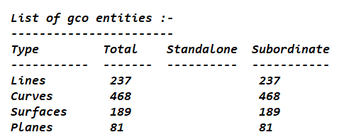
%TSC_TEMP_DIR%\Read_to_viewer_<input_part_name>.log
Where: <input_part_name> is the name of the input part (or the active part name in interactive usage)
This contains information describing the 3DExperience ‘data read’ processing into Theorem Intermediate data format. Normally a list of entities.
%TSC_TEMP_DIR%\viewer_<part-name>_screen_output.log
Where <part-name> is the selected output file name.
This contains the screen output of the process of writing the data to Creo View. The status of the translation can be found here.
%TSC_TEMP_DIR%\viewer_<part-name>.log
Where <part-name> is the selected output file name.
This contains detailed process information of the write of the data to Creo View and contains additional information such as modifiers and options used.
3DExperience Environment Files
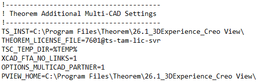
As part of the Theorem installation process, a set of 3DExperience environment files are created which are subsequently used in the launch of 3DExperience and CATUtil sessions to support the Theorem partner plug- ins for Creo View export.
A ‘CATEnv’ file is created for each installed version of 3DExperience.
These environment files are located in the 3DExperience revision specific folder e.g.
<installation_directory>\B423\win_b64\CATEnv\Theorem_Multi-CAD_CREOVIEW_CATIAV6R2021x.txt
<installation_directory>\B424\win_b64\CATEnv\Theorem_Multi-CAD_CREOVIEW_CATIAV6R2022x.txt
<installation_directory>\B425\win_b64\CATEnv\Theorem_Multi-CAD_CREOVIEW_CATIAV6R2023x.txt
These files consist of the current 3DExperience settings with the required Theorem settings appended at the bottom.
Creating a Login Ticket
Use a browser link (similar to the one below) to your 3DExperience Server
https://3dspace.2017x.theorem.com:447/3dspace/common/emxNavigator.jsp
A page will appear in the browser.
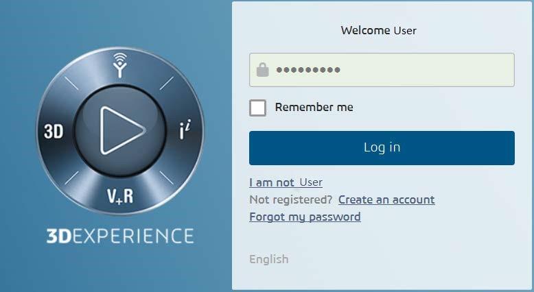
Login as normal, e.g.
User
Password
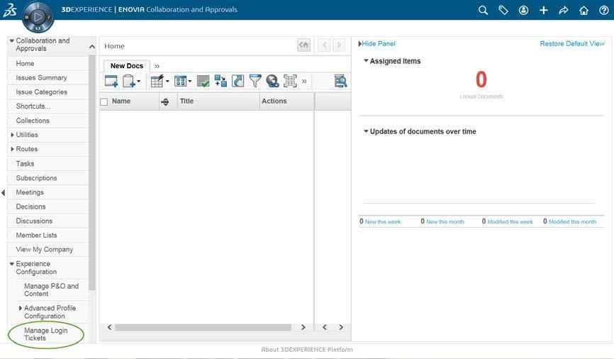
Select Collaboration and Approvals > Experience Configuration > Manage Login Tickets
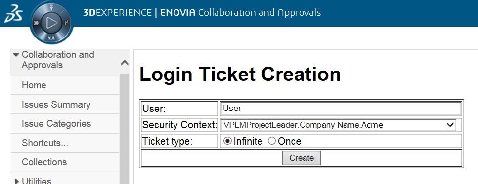
Select the values required for your user:
User and Security Context should already be set, make sure that Ticket Type: Infinite is selected. Then click on ‘Create’.
‘Create’ will produce the ticket. See example below:
REEyNzM3STE1MER2NDgxQzlFNzk1QzIwNjZGNATzDAN8Um9iaW58Um9iaW58fHwwfA==
This can then be used as the ‘LoginTicket’ value explained previously.