User Guide
Translation Configuration
It is recommended that the CATIA V5 to Creo View Adapter be run from a pre-created configuration. We have adopted the standard PTC Configuration tools which will create a batch script for running the Adapter on the command line and also a worker script to allow the Adapter to be run with Windchill.
To take full advantage of the configuration tools and to configure the Adapter for use as a Windchill Worker please contact your PTC representative to provide the Windchill Installation and Configuration Guide Catia5_CreoView.
Configuring the CATIA V5 Creo View Adapter using the Recipe Editor
The Recipe Editor
This section of the User Guide describes the available configuration options provided by the recipe editor. A recipe is a set of user-defined rules that drive the individual CAD Adapter. The recipe concept provides a solution to the problem of efficiently converting CAD data into a form suitable for viewing on a wide range of computer platforms. Like its analogy in cooking, gaining a desired result requires cooking to a specific recipe. While most CAD parts will convert into an efficient form for large-scale visualization, some parts require modifications to the standard visualization recipe to be viewed effectively.
The CATIA V5 Adapter is provided with a master or default recipe file. This file is pre-configured to allow the visualization of most objects. The master recipe file should not be edited. Instead, additional new recipes can be created from this default file using Save As functionality in the recipe editor (rcpedit) provided with the translator.
For full details concerning the Recipe Editor, please refer to the ‘Creo View MCAD Adapters Installation and Configuration Guide’ document, which can be obtained via the PTC Reference Documents Site at https://www.ptc.com/appserver/cs/doc/refdoc.jsp. The SpinFire convert Creo View Adapter uses the standard PTC mechanism to Configure translation options. The basic concepts and available options are covered here for convenience.
We also provide a configuration script to allow a recipe file to be created. Running the following script will launch the Recipe Editor Configuration Tool:
<Translator_installation_directory>\bin\catia5_pv_config.cmd
The panel below will be displayed:
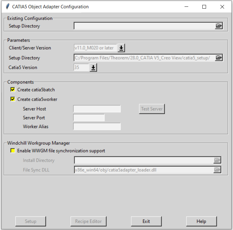
The Configuration Tool allows the CATIA V5 Creo View Adapter to be configured for use in batch (via the command line) and/or for use in a Windchill environment (catia5worker). Please contact your PTC representative to provide the Windchill Installation and Configuration Guide Catia5_CreoView for full details on configuring in a Windchill environment.
This guide will focus on running the translator from the command line, but all of the configuration options are available in both environments. The ‘Create catia5batch’ selection will create a recipe file for batch and the ‘Create catia5worker’ will create a recipe file for a Windchill invocation. Having selected either of these options (and provided a valid Windchill Host and Port) the ‘Setup’ button will become active. Selection of the ‘Setup’ button will launch the following panel:
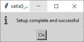
This can be accepted and the ‘Recipe Editor’ button will become active. The ‘Setup’ action will create a new directory beneath the translator installation directory, so, the user that creates new configurations will need write access to the translator installation directory. The first configuration directory will be named catia5_setup. Subsequent configurations will be named catia5_setup’n’ (where ‘n’ is a unique number). In this manner many different configurations can be created. The configuration directory will contain an invocation script that will deliver a default Configuration that uses default translation settings. Selection of the ‘Recipe Editor’ button will allow the user to set specific translation settings. The contents of a Configuration folder are:
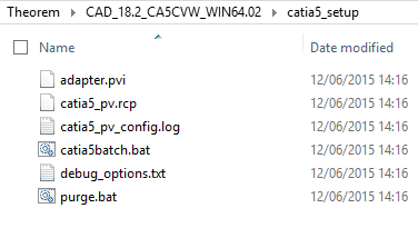
The catia5batch.bat script will be used in preference to the SpinFire Convert provided script discussed in the Default Translation on the Command Line section and will use the configuration options specified in the catia5_pv.rcp (recipe) file.
Running a translation using the catia5batch.bat script can be achieved using the following command:
<Translator_installation_directory>\catia5_setup\catia5batch.bat <input_file> -p <output_path> -o <output_file>
The results and screen output will be the same as that noted for the Default Translation.
Changing the translation options in the configuration recipe file is achieved by selecting the ‘Recipe Editor’ button. This action will display a number of panels that are of interest to the SpinFire Convert CATIA V5 Creo View Adapter.
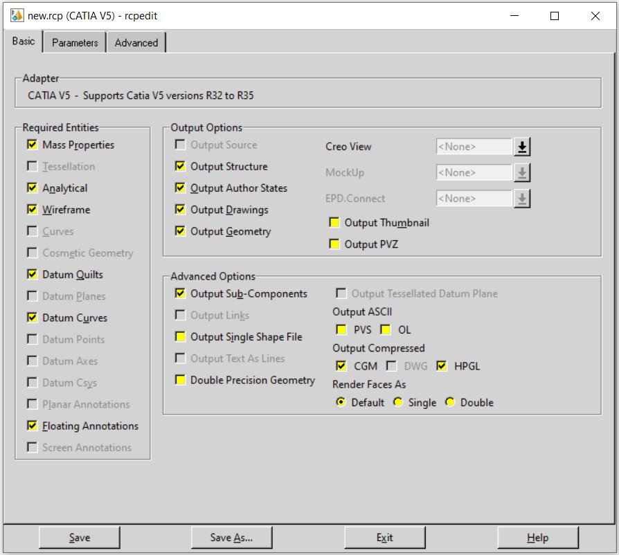
Please note that the Mass Properties option toggled on by default in the Basic tab in the recipe editor will read all the mass validation properties including volume, area, COG and density as per the material applied. This will provide a true mass value in the Creo View output. This will not be the case if this option is toggled off. A mass value will be calculated in Creo View; however, this will not be calculated with the density of the material, consequently meaning that the mass value displayed will not be a true reflection of the actual mass.
The main page provides standard PTC options and these are well documented in PTC’s ‘Creo View MCAD Adapters Installation and Configuration Guide’ document, which can be obtained via the PTC Reference Documents Site at https://www.ptc.com/appserver/cs/doc/refdoc.jsp.
Instead, we will focus on the SpinFire Convert specific settings that affect the output. These are accessible via the Advanced Tab and are grouped into 4 sub pages:
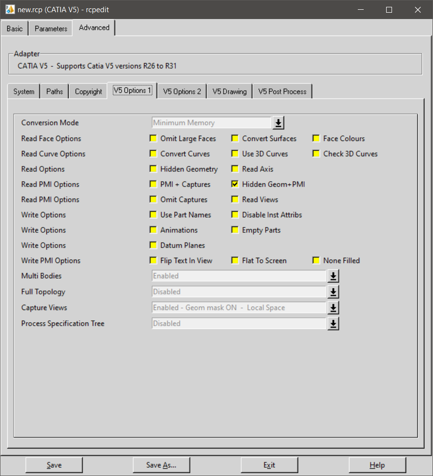
V5 Options 1 – General translation settings (Including PMI)
V5 Options 2 – More translation settings
V5 Drawing – Options relating to CATDrawing processing
V5 Post Process – Options relating to additional formats
V5 Options 1 – General translation settings (Including PMI)
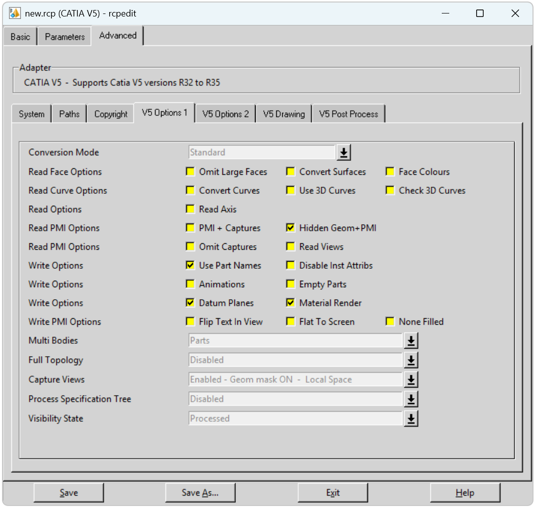
Each of these options is described below:
Option |
Description |
|---|---|
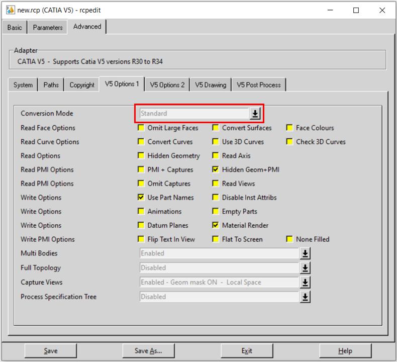
Conversion Mode |
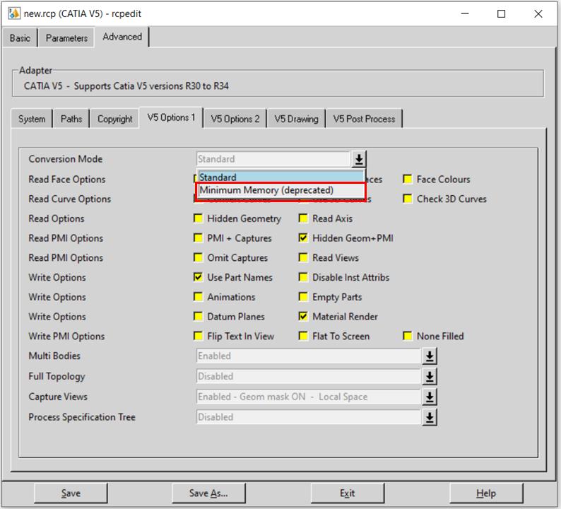
The recommended mode for processing assembly information is the Standard conversion mode option. This is the default applied. This reads a CATIA V5 assembly and its entire geometry contents into memory, before writing out all of the data to Creo View. |
Omit Large Faces |
Allows the user to omit large PLANEs where the bounding exceeds 0.1Km in any direction. These
faces are most often construction planes. The bounding box size can be adjusted by using the
additional argument |
Convert Surfaces |
Allows the CATIA V5 API to convert analytical surfaces as NURBs, this may be useful from time to time if face/surface errors occur in the CATIA V5 read. (Often used in conjunction with Convert curves). |
Face Colours |
By default individual face colours are not read, this option enables individual face colours to override solid colours. |
Convert Curves |
Allows the CATIA V5 API to convert analytical curves as PCURVES, this may be useful from time to time if edge/curve errors occur in the CATIA V5 read. (Often used in conjunction with Convert surfaces). |
Use 3D Curves |
This option allows Creo View API to generate its own 2D curves. This option is most likely only ever used as a work-around when poor data is encountered. |
Check 3D Curves |
This option allows the Adapter to test the data and if necessary automatically enable Use 3D Curves.
A default tolerance of 0.01 (1%) face/surface overlap being used for these checks. This tolerance
can be adjusted with |
Read Axis |
Enables the reading of CATIA V5 axis systems. |
PMI + Captures |
Please note! This feature will require additional SpinFire Convert licenses. See the CATIA V5 to Creo View with PMI demonstration video for full details. Enables the read of PMI stroked and semantic data. Reading of captures is automatically enabled. |
Hidden Geom + PMI |
Read PMI Annotation set construction geometry. Default is ON. |
Omit Captures |
Reads only the Views if the option below is checked. |
Read Views |
Optionally read views, when reading PMI. |
Use Part Names |
Use the CATIA V5 ‘part number’ names for assembly nodes. The default is to use ‘Instance name’. Use Part Names is ON by default. |
Disable Inst Attribs |
Disables the output of any instance attributes. |
Animations |
Please note! This feature will require additional SpinFire Convert licenses. Outputs one or more .fra animation files, which can be imported into any Creo View viewer that supports animations. The .fra files will be created alongside the output .pvs file, in the same location and with the same base name. If the animation has a title (name) this will be appended to the base name, for example: C:\TEMP\chainsaw.pvs will result in: C:\TEMP\chainsaw_removeCover.fra The .fra files are created by default in mm. |
Empty Parts |
Creates an empty (contains a single point at X0,Y0,Z0) dummy .ol file for empty nodes, to force the geometry node creation, where no geometry exists. |
Datum Planes |
Allows large planes to be created as genuine Creo View datum planes. Default is ON. The visibility of these planes in Creo View is determined by the Datum Planes option in the Model – Filters tab within the Active View in the Creo View Options window. This option will need to be toggled on in order to view these datum planes in Creo View. 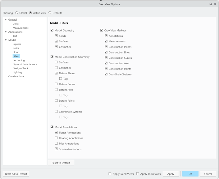
|
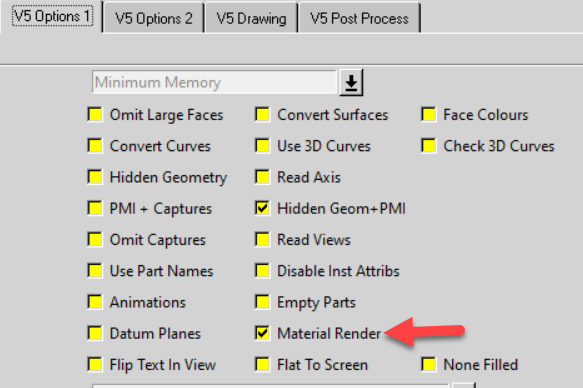
Material Render |
Enables both the material information and render to be read and displayed in the Creo View output. This option will also try to render the Creo View output using the CATIA material attributes. Default is ON. |
Flip Text In View |
NOA data read from CATIA V5 may be flipped so that it is readable from any given capture view. This option adjusts the text to mimic the behaviour of the CATIA V5 application. |
Flat To Screen |
Text And NOA data read from CATIA V5 that is ‘flat to screen’ will be written ‘flat to screen’ with this option set. In order for this option to work, the semantic PMI MUST be read, which means the Read PMI option MUST be set to Enabled. Please note that these entities are Floating Markup in the Creo viewer. In order to see them in the viewer these entities should be ‘enabled’ (see MODEL ANNOTATIONS NAVIGATION FILTERS panel in the Creo Viewer and ensure FLOATING ANNOTATIONS is selected). It also may be necessary to select floating annotations and (Right Mouse Button) select ‘show’ to see them in Creo viewer. |
None Filled |
Disable the writing of filled (solid) arrow heads and text, as read from CATIA V5. Only provide an outline style. |
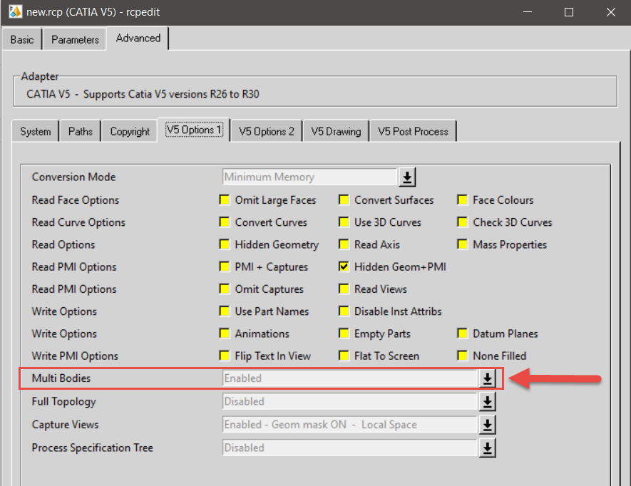
Multi Bodies
Enables the display of individual solids within a part. Options are:
Disabled
Parts (Default)
Enabled
Fully Expanded
Disabled |
Will not create extra structure. All geometry will be created under the part node. |
Parts |
Will maintain the specification tree structure. Each node will be created whether they include solids or are empty. All surface and wireframe geometry are placed under the part. This is the default setting. |
Enabled |
Where top level data has multiple solids, these solids will be displayed as separate nodes in the Creo View specification tree when Enabled is applied. This means that these nodes can be selected individually and subsequently shown or hidden. Any non-solid data will be left at the top level. As a special case any single face OPEN Solids are not treated as solids. |
Fully Expanded |
Similar to Enabled, however with the Fully Expanded option, the single Face OPEN solids are treated as solids and so will have their own node, as will any non-solid data which will be added collectively in an additional sub-nodes. |
Full Topology
Controls how the topology is written into Creo View data. By default this is ‘disabled’, which is consistent with earlier releases of the product. The default setting generates good viewable data, but since each face of a solid is written separately it is not possible to calculate mass properties such as volume, correctly view capping sections or perform 3D Compare or Interference Detection in the Creo View client. Options are:
Disabled (Default)
Enabled – (Solids only)
Enabled – (Solids & Quilts)
Enabled – (Solids only) Fix non-manifold
Enabled – (Solids & Quilts) Fix non-manifold
Disabled |
Solid faces written with unique edges. This is the default setting. |
Enabled |
(Solids only) – Adjacent faces share edges, such that the resulting Creo View data can support mass properties etc. (Solids & Quilts) – Adjacent faces share edges, this includes ‘open solids’, which will be written into Creo View as quilts. (Solids only) Fix non-manifold – As above with additional behaviour needed to resolve non-manifold conditions caused by CATIA V5 add operations. (Solids & Quilts) Fix non-manifold – Both solids and open solids processed and resolve non-manifold conditions caused by CATIA V5 add operations. NOTE! Enabling full topology can increase translation times, so we suggest that the user selects the minimum setting that required. For example, don’t use the Fix non-manifold settings unless necessary and don’t use the Quilts setting unless required. |
Capture Views
Allows control over the processing of any PMI capture data. Options are:
Disabled
Enabled – Geom Mask ON – Local Space (Default)
Enabled – Geom Mask OFF – Local Space
Enabled – Geom Mask ON – Global Space
Enabled – Geom Mask OFF – Global Space
Disabled |
Do NOT write captures. |
Enabled |
Geom Mask ON – Local Space: This will ensure that only the geometry associated with a given capture view is displayed in that view. This is the default setting. Geom Mask OFF – Local Space: Allow users to have all geometry displayed in every capture view. Geom Mask ON – Global Space Geom Mask OFF – Global Space Points to note are:
|
Process Specification Tree
Please note! This feature will require additional SpinFire Convert licenses. Allows Model Based Definition (MBD) data to be read. Options are:
Disabled (Default)
Enabled
Enabled – Expanded
Disabled |
Does not read the specification tree (MBD). This is the default setting. |
Enabled |
The specification Tree setting will provide a true representation of the Geometry and PMI entities in the capture views when used in conjunction with the setting: Capture views = Enabled – Geom Mask ON |
Enabled – Expanded |
The specification Tree is read to a deeper level which supports the ‘initial view state’ of views – please note this option can produce many more output files. |
Visibility State
Controls the visibility state of hidden geometry and assembly nodes. Options are:
Disabled
Processed (Default)
Enabled – Occurrence
Disabled |
Will ignore the visibility state of solids and assembly nodes. |
Processed |
Reads hidden geometry and assembly nodes and maintains their visibility state when opened in Creo View, mimicking CATIA V5. Only exception is for multi-instanced parts. This is the default setting. |
Processed – Occurrence |
Similar to Processed, however the Processed – Occurrence option allows multi-instanced parts to maintain their individual visibility state. |
V5 Options 2 – More translation settings
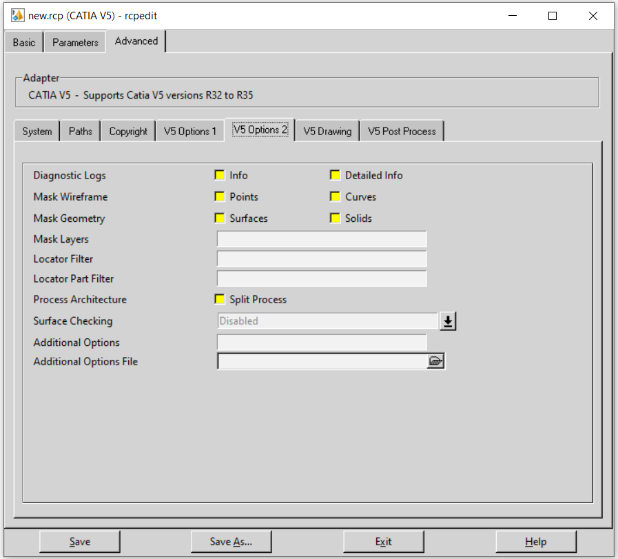
Each of these options is described below:
Option |
Description |
|---|---|
Info (Diagnostic Logs) |
Generate a more verbose log file. |
Detailed info (Diagnostic Logs) |
Used as a diagnostics level of detail in the log file (for debug purposes only). |
Points (Mask Wireframe) |
Turn off Point processing. By default, points are translated. |
Curves (Mask Wireframe) |
Turn off Wireframe Curve processing. By default, curves are translated. |
Surfaces (Mask Geometry) |
Turn off Surfacing processing. By default, surfaces are translated. |
Solids (Mask Geometry) |
Turn off Solid processing. By default, solids (or Breps) are translated. |
Mask Layers |
By default, ALL layers are translated. This field allows the user to select which layers ARE translated. The syntax for this field is limited to ranges of layer numbers (separated by ‘-’) and individual layer numbers; each range and individual number being separated by a comma ‘,’. e.g. Means layers 20 through to 30 AND 45 AND 100 through to 300 WILL be translated. The full range of layers is 0-1023. |
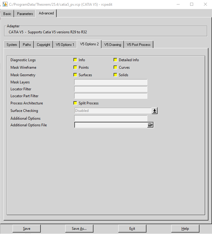
Locator Filter |
Enables filtering of locator axis systems and can be filtered using wildcards such as:
|
Locator Part Filter |
Enables filtering of parts that contain locator axis systems and can be filtered using wildcards such
as: |
Split Process (Process Architecture) |
This option may aid some specific data issues BUT it should only be used with guidance by the SpinFire Convert support team. |
Surface Checking |
Generates a report file that details any points on the output Creo View surfaces that deviate by a distance greater than a selected tolerance. Also, optionally, the output Creo View data can be annotated with ‘surface check’ points to indicate where these points are. This is achieved by selecting one of the tolerance suffixed with (plot points). The ‘surface check’ points are coloured green for within selected tolerance and red for outside selected tolerance. The report file is created alongside the progress file and will be named
SURFACE CHECKING COMPLETEPLEASE CHECK : Some Surface check issuesFound [4434] points <= Gap Tol (green points) [0.001]Found [1544] points > Gap Tol (red points) [0.001]Found [0] points > Gap Limit (calc errors) [1]Largest Gap Valid [0.00992005] found at Idx [1202]The default is set to Disabled. |
Additional Options |
Not ALL options for the CATIA V5 Creo View Adapter are made available to the recipe editor. These options are not in common use but are included here should they ever be required. If additional options are required, then these can be added to the Additional Options field, delimiting each option with a space (” “) character. This field is functionally equivalent to the additional options file field, however settings made here will override the settings in the options file. This field allows for quick transient tests to be performed, without the need to edit the additional options file. Some examples of additional options are as follows:
|
Additional Options File |
Any of the Additional Options can be specified in an Additional Options File, known as a ‘ts_cfile’. See Property Mapping Files for the format of a SpinFire Convert Configuration File. |
V5 Drawing – Options relating to CATDrawing processing
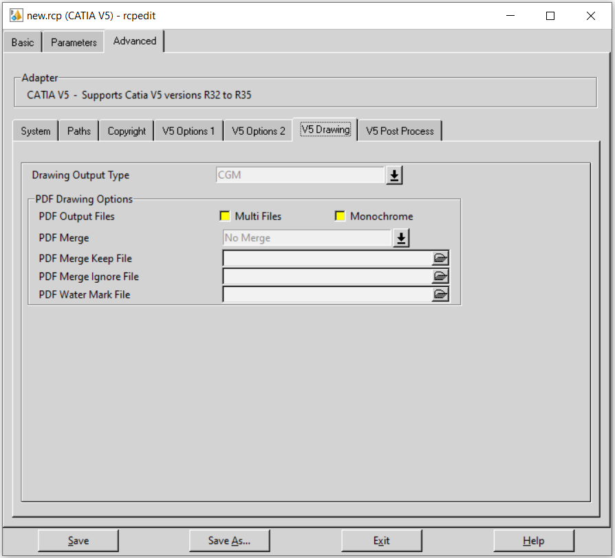
Each of these options is described below:
Option |
Description |
|---|---|
Drawings Output Type |
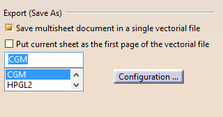
Allows the output format for Drawing processing to be specified. The default is CGM. CGM, PDF, HPGL or TIF can be specified, these options, however, do not offer the multi-sheet output that is present in the DXF format. |
Drawing Output Files |
2 options are available to select. These are Multi-Files and Monochrome. Multi-Files – When processing drawing files with multiple sheets, the output is controlled by a combination of the CATIA5 option ‘save multi-sheet document in a single vectorial file’ (v5-save-single-file) and the Multi-Files recipe setting. See Property Mapping Files – Drawing Processing Options for how these values should be used. Monochrome – Will change the PDF to a monochrome output using a 3rd party application (Not provided by Tech Soft 3D). |
PDF Merge |
Note! This option is only available when Drawing Output Type is set to PDF, it is used to add additional control over the election of multiple sheets. Note! The Multi-Files option cannot be selected for this option. The following options are available from the pull-down:
|
PDF Merge Keep File |
Specify the ‘keep’ file list for the PDF Merge -> Keep Files setting. |
PDF Merge Ignore File |
Specify the ‘ignore’ file for the PDF Merge -> Ignore Files setting. |
PDF Water Mark File |
Allows the selection of an image file, in either JPG or PNG format, that will be merged into the PDF file as a watermark. This option only works if one of the PDF Merge options are selected (i.e. it will NOT work if No Merge is selected). Note! The watermark files are not scaled; the user must provide the correct page size/format to match the input drawing. |
V5 Post Process – Options relating to additional formats
Please note! This Processing feature will require additional SpinFire Convert licenses.
The JT export is provided via the CATIA V5 Creo View Adapter – JT Add On module and requires an additional SpinFire Convert license. JT export also requires a configuration file to control the output. The default configuration file is located at %TS_INST%/etc/tess.config. The user can edit this, to suit their tessellation quality and output requirements.
The 3DPDF export is provided via the CATIA V5 Creo View Adapter – 3D PDF Add On module and requires an additional SpinFire Convert license. 3DPDF export also allows for templates to be selected to control the page layout and export options.
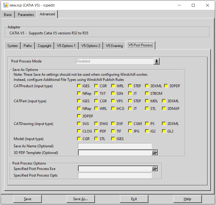
Each of these options is described below:
Option |
Description |
|---|---|
Post Process Mode |
There are 3 modes available for Post Processing: Disabled – Post Process is disabled. Saves As – Activates the following selections in the page:
Post Process – Activates the following selections in the page:
|
Save As CATProduct (input type) |
This set of check boxes enables the selection of file types that are required to be created (i.e. JT, 3DPDF) when Processing CATProducts with SaveAs selected as the Post Process Mode. Note! SSN denotes a CATIA Session file. |
Save As CATPart (input type) |
This set of check boxes enables the selection of file types that are required to be created (i.e. JT, 3DPDF) when Processing CATParts with SaveAs selected as the Post Process Mode. Note! NRep denotes a CATIA NavRep file. |
Save As CATDrawing (input type) |
This set of check boxes allows the selection of file types that are required to be created (i.e. DWG, JPG) when Processing CATDrawings with SaveAs selected as the Post Process Mode. Note! CLOG denotes a CATIA CATOLOG file. |
Save As Model (input type) |
This set of check boxes allows the selection of file types that are required to be created (i.e. STL, IGES) when Processing Model files with SaveAs selected as the Post Process Mode. |
SaveAs Name |
This field allows the base name of the ‘SaveAs’ files to be specified, the default being the same name as the input file. |
3D PDF Template |
Enables a PDF template to be specified when saving to the 3DPDF file type. |
Specified Post Process Exe |
When Post Process Mode is set to Post Process, this field allows ANY post process executable or script to be specified. This allows customers to link in their own post processing behaviour. The specified Post Process executable will be called as follows:
|
Specified Post Process Opts |
Specify arguments to be passed to the Specified Post Process Executable. |
Creating a New Recipe File
If a new recipe file is required, launch the rcpedit.exe command from within the
<Translator_installation_directory>\bin directory in your SpinFire Convert install.

Select the relevant options in the rcpedit window, then select Save As.
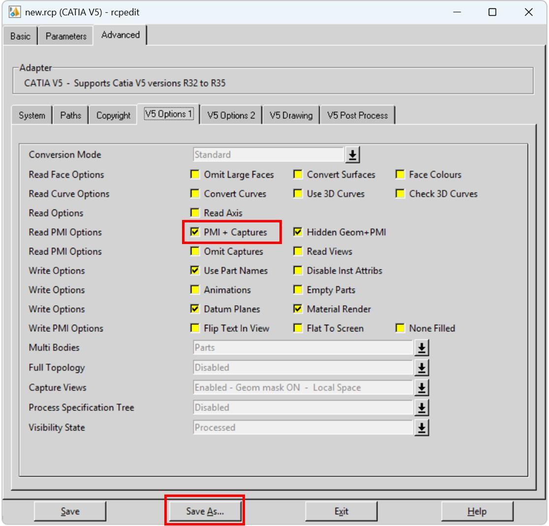
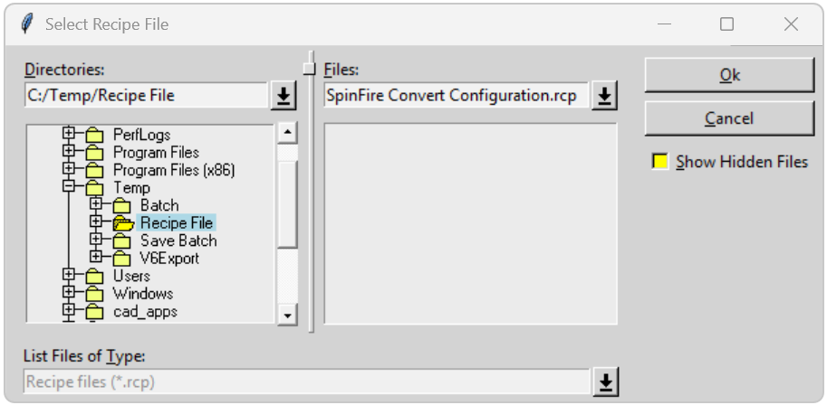
Select the required directory and input a filename, then click OK.

Alternative File Output (Additional File Types)
The Adapter supports the generation of the same alternative file types (Additional File Types) as listed in the Post Processing SaveAs section, using a WVS Publish Rules ‘job’ file.
The syntax of invoking the Adapter with a job file is as follows:
catia5batch.cmd -j <job_file.paj>
Where an example job file format is:
<?xml version="1.0" encoding="UTF-8"?>
<publish>
  <input filename="as1.CATProduct"/>
  <output typename="ALTFILE">
    <file display-name="drw1" type="CGR” output-prefix="cc" output-suffix="ss">
    </file>
    <file display-name="drw4" type="IGES" output-prefix="m" output-suffix="uu">
    </file>
    <file display-name="drw5" type="STBOM" output-prefix="h" output-suffix="uu">
    </file>
    <file display-name="drw6" type="TXT" output-prefix="t" output-suffix="uu">
    </file>
    <file display-name="as1" type="PDF" output-prefix="t" output-suffix="uu">
    </file>
    <file display-name="as1" type="JT" output-prefix="t" output-suffix="uu">
    </file>
  </output>
</publish>
The <file…> elements used in the .paj file result from the same entries being used in Windchill’s WVS Publish Rules XML definition for the <additional-files…> elements.
This .paj file shows CGR, IGES, STBOM, TXT, PDF and JT files being created for the ‘as1.CATProduct’ input file used in the example job file above. All of the alternate formats (Additional File Types) will be packaged into a .pvoa file which will also include the pvs and ol files.
It is important to check that the correct CATIA V5 licenses are available, since some alternative file types are licensed. This can be carried out via the ‘SaveAs’ menu option from the CATIA V5 application. If the required type can be saved interactively then the ‘Alternative File Output’ mechanism should operate successfully.
Please note! The output prefix and output suffix values are added to the output file names generated by the translation, so in the JT example above the resultant file name would be t_as1_uu.jt. If these strings are empty the pre/post fix is an “_” (underscore). So, for the JT example above, if both strings were empty the resultant file name would be _as1_.jt.
Further details can be found in article CS111916 – How to configure Additional File Types to be published for specific CAD Document types in Windchill PDMLink?
Translating on the Command Line
Default Translation on the Command Line
Running a translation via the command line can be carried out without using a pre-created configuration. This
will use the default translator settings. This is achieved by directly running the script file located in the
<Translator installation_directory>\bin directory. The format of the command is as follows.
(Note! The [XX] seen in the example below will be replaced with the version of CATIA V5 that you are using. For example, if you are using R35 then catia5r35 will be displayed.)
<Translator installation_directory>\bin\catia5rXX_pv.cmd <input_file> -p <output_path> -o <output_file>
The example above will translate the file to the output path specified. In this case:
C:\temp\samples output\nist_ctc_02_asme1_ct5210_rc.pvs
C:\temp\samples output\nist_ctc_02_asme1_ct5210_rc.ol

The following screen output should be expected when successfully translated:
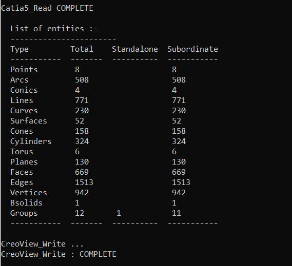
The above example provides the minimum command line arguments required to create an output. In order to support the PTC Windchill interface, we have also adopted the PTC Adapter command line syntax. A full list of available options are shown below and can be displayed by issuing the following command:
<Translator_installation_directory>\bin\catia5rXX_pv.cmd -h
Setting |
Result |
|---|---|
<@File> |
Read Options from the response file <file> |
-?-h |
For basic help page. UNIX may try to export the “?” so –h should be typed in quotes, for example, “h”. |
-d <depth> |
Set the conversion file depth. When converting an assembly file determines to what depth the hierarchy should be traversed. The default is all. |
-H |
For extended help options |
-o <name> |
Set output file base name (number of input files must be 1). |
-p <name> |
Set output base path. |
-r <name> |
Set recipe to <name> |
-vc |
Disable all console print-out. |
-vc1 |
Redirect all console print-out to stdout. |
-vc2 |
Redirect all console print-out to stderr (default) |
-ve[n] |
Increment or set (if[n]is given) the error reporting level. –ve0 disables all error reporting, default 1. |
-vl <file> |
Direct all printed output to <file> |
-vL <file> |
Concatenates all printed output to <file> |
-vn <file> |
Direct all printed output to new log file <file>-#.log. |
-vp <n> |
Set the process verbosity flag. List the modules by –I. Flags are listed in the source code. |
-vw[n] |
Increment or set the warning reporting level, see -vc |
-vt |
Give the current date/time stamp with all print outs. |
-j <name> |
Get job from <name> .paj file |
-epdconnect |
Enable EPD.Connect orientated conversion. |
-mockup |
Enable MockUp oriented conversion process |
Translating with a Recipe File on the Command Line
A recipe file which includes a set of options defined by the user in the recipe editor (rcpedit) can also be added to a command in the command prompt window using the correct syntax.
The format of the command which includes a recipe file is as follows. (Note! The [XX] seen in the example below will be replaced with the version of CATIA V5 that you are using. For example, if you are using R34 then catia5r34 will be displayed.)
<Translator installation_directory>\bin\catia5rXX_pv.cmd <input_file> -p <output_path> -o <output_file> -r <recipe_file>
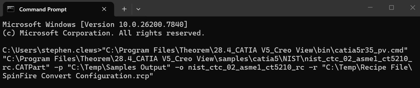
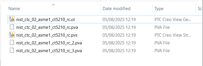
The example above will translate the file with the options defined in the recipe file to the output path specified. In this case:
C:\temp\samples output\nist_ctc_02_asme1_ct5210_rc.pvs
C:\temp\samples output\nist_ctc_02_asme1_ct5210_rc.ol
C:\temp\samples output\nist_ctc_02_asme1_ct5210_rc.pva
C:\temp\samples output\nist_ctc_02_asme1_ct5210_rc_2.pva
C:\temp\samples output\nist_ctc_02_asme1_ct5210_rc_3.pva
Translating Interactively from within CATIA V5
Launching CATIA V5 with SpinFire Convert plug-ins
The CATIA V5 to Creo View adapter allows an active CATIA V5 Part or Assembly to be exported directly to Creo View from within the CATIA V5 application.
In order to translate from within CATIA V5, the application must be started using a SpinFire Convert environment, so that the appropriate plug-ins are available.
CATIA V5 can be started from a desktop shortcut created during installation.
Alternatively, it can be started via the script provided in the translator installation located in:
<installation_directory>\bin
The script name is:
catia5r<version>_start.cmd
Where <version> is the version of CATIA V5 that you have installed – e.g. 32 for V5-6R2022, 33 for V5-6R2023, 34 for V5-6R2024, 35 for V5-6R2025 etc.
Default Translation from CATIA V5
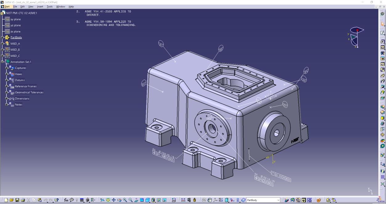
Once CATIA V5 has been started, open the part or assembly that is going to be exported to Creo View.
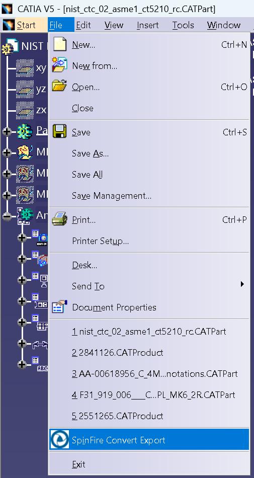
Select File, then SpinFire Convert Export.
This will launch the SpinFire Convert Export panel.
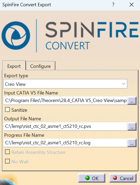
The Export tab displays the Export type, Input CATIA V5 File Name, Output File Name and Progress File Name. The Input CATIA V5 File Name, Output File Name and Progress File Name fields will be prepopulated if a model is already loaded into the CATIA V5 session, however, the Output File location and Progress File location can be modified by clicking on the icon.
The Configure tab allows the user to select a Configuration.
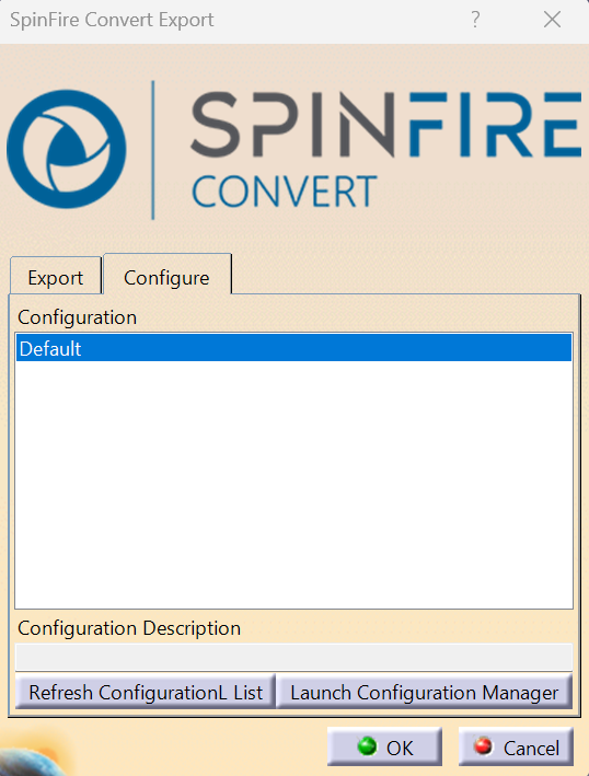
In this tab, a list of configurations that are available to use will be displayed including the standard Default configuration.
When a configuration has been selected, click OK to initiate the translation. The configuration will be highlighted in blue once it has been selected.
The active part or assembly will then be translated to Creo View with pvs and ol files created in the output directory specified. A pop-up message will be displayed to confirm when the translation is complete.
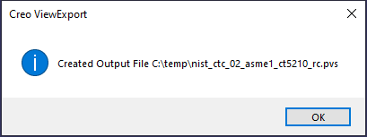
Configuration Manager
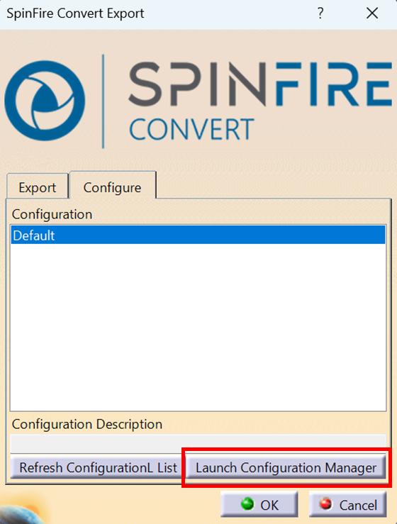
If a suitable Configuration is not available or if a different configuration is required, then a new Configuration can be created by the user. To create a new configuration, select the ‘Launch Configuration Manager’ command.
In the configuration manager window, select New, then rename the configuration as required.
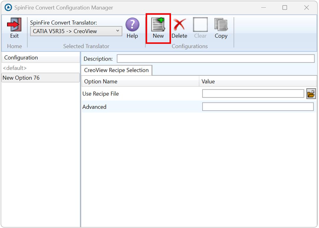
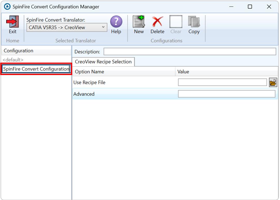
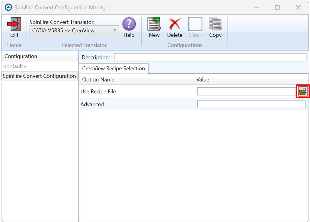
In the configuration manager window, only 1 tab will be displayed named CreoView Recipe Selection which will include a Use Recipe File option. To add a recipe file to the configuration, select the folder icon next to the Use Recipe File option field.
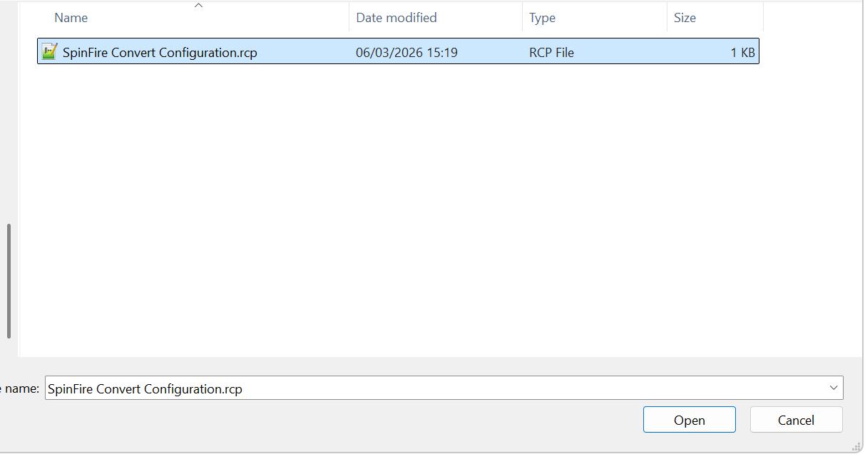
In the Select a CreoView Recipe file pop up window, navigate to the directory where the recipe file is saved. Select the file and click Open.
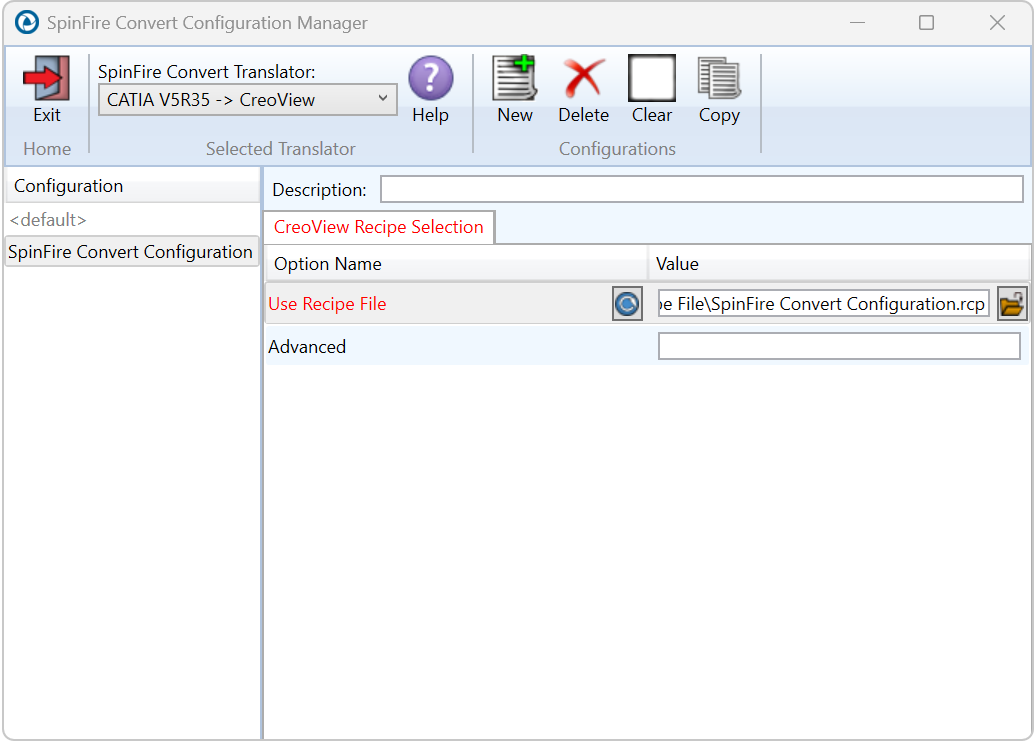
The recipe file will then be added to the configuration. Click Exit to close the Configuration Manager window.
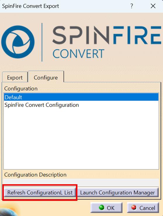
Any new configurations created will be displayed in the Configurations list once it has been refreshed. To do this select ‘Refresh Configuration List’.
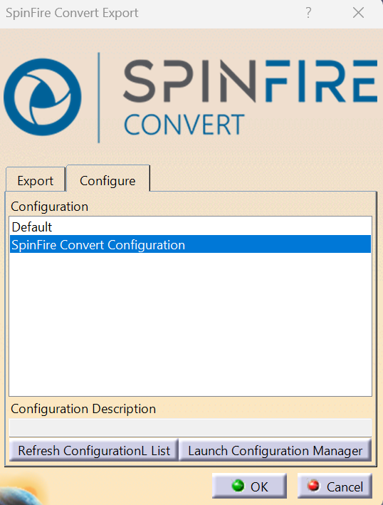
Select the new configuration to make it the active configuration.
Assembly Processing
Processing CATIA V5 Assemblies (.CATProduct files)
Assuming that the input to the Adapter was a single assembly named test_assembly.CATProduct related to many subordinate parts (.CATPart) files then the output from the translator will be a single Creo View assembly file test_assembly.pvs plus many geometry .ol files, one for each part file processed.
If the assembly file had additional assembly files subordinate to it then all of the accumulated assembly hierarchy information would be output into the top level Creo View .pvs file.
The CATIA V5 Creo View Adapter takes advantage of the latest Creo View dAPI which writes .pvs files (Creo View binary assembly structure files) by default. If a user wishes to write out earlier .pvs versions or .ol files, this can be achieved via the appropriate setting in the recipe editor.
Processing CATIA V5 Parts (.CATPart files)
For each part (.CATPart) file processed individually then the output from the translator will be a single Creo View assembly .pvs file and a single geometry .ol file.
Therefore, assuming that the file being processed was named test_component.CATPart then the output would be test_component.pvs and test_component.ol
Processing CATIA V5 Drawings (.CATDrawing files)
For each drawing (.CATDrawing) file processed individually the translator will output a (by default) DXF (.dxf) file per sheet found in the .CATDrawing file. The final output to the user is a Creo View assembly file and one or many .dxf format files.
Therefore, assuming that the file being processed was named test.CATDrawing then the output would be test.pvs and test_sheet1.dxf, test_sheet2.dxf, etc.
The user can alternatively elect to output drawing files in several formats including CGM, HPGL, PDF or TIF. These can be selected via the recipe editor.
Error Tracking and Management
A method of tracking and managing errors output from the CATIA V5 to Creo View process has been provided. This is implemented by setting exit status codes from the Adapter and additionally the creation of a summary file for each translation task. The structure of the summary file enables detailed analysis of the translation task to be verified.
Adapter Exit Status Codes – The software will return one of the following exit status codes:
0 = Translation completion without errors
1 = Translation completed with errors
These codes will be returned regardless of the type of data being processed, either single parts or assemblies. If the error code returned is 1 (e.g. Completed with errors) the user will be directed to look at a summary file that details the exact reason for failure.
Summary File Definition – Each translation creates a summary file using the standard name “tscsummaryyj” located in the temporary directory. The user can override the default name using the environment variable TSC_SUMMARY_FILE.
The name of the active summary file is recorded in the progress file:
WINDOWS default name=%TEMP%\tscsummary
Output is recorded in the summary file with a single line reporting a status for each item processed. Each line is defined using 4 fields, separated by a “,” character. Each field represents the following data:
Field 1 = Input File Name
Field 2 = Error Code (See Summary File Error Codes)
Field 3 = Error Description (See Summary File Error Codes)
Field 4 = Progress File name
e.g. C:\myparts\sample.CATPart,0,Completed with no errors,/usr/data/sample.CATPart.log
When processing either single parts or assemblies using the default recipe file settings, only one line will appear in the summary file. However, for assemblies processed with links enabled, the summary file will contain a line for each “.CATPart” and “.CATProduct” file translated.
Summary File Error Codes – The following Error Codes are output the Summary File:
0 = Completed with no errors
-1 = Command line syntax error
-2 = Licensing Error
-3 = Input File Not Found
-4 = Failed to Open Progress File
-5 = CATIA V5 Library incompatibility
-6 = General Read Error
-7 = General Write Error
-8 = No Entities Found
-9 = CATIA V5 Environment problem
-10 = Failed to open CATIA V5 file
-11 = CATIA V5 Session failure
-12 = Solid validation error
-13 = Some solid degradation
-14 = One or more faces omitted
-15 = One or more geometry files not found in an assembly
-16 = Invalid Output Type Specified for Drawing
Worker Logs – The Adapter writes key messages to the PTC worker logs, these include the summary error codes (positive values are used in these logs, e.g. 3 = input file not found).
The SpinFire Convert messages added to the worker logs are always prefixed by ‘TS:’ and are written at two levels of detail 0x01 and 0x10. These messages are enabled via the –vm command, e.g.
-vm 1will enable all 0x01 messages-vm 11will enable all 0x01 AND 0x10 messages.
The -vL <log file> command line can be used to re-direct these messages to a file.
In the event of an error the summary code will be written to the worker log the positive value of the summary code, 8 => No entities found.
Process Timeouts – Timeouts allow a user to control when an individual translation invoked from a Windchill environment should timeout.
The Windchill interface allows 2 distinct timeout types to be defined, Long and Short.
Three simple timeouts have been allocated to the CATIA V5->Creo View translator, one using the Short Timeout value and two using the Long Timeout value setting:
Short Timeout – Catia5_Access, providing initial access to CATIA V5
Long Timeout – Catia5_Read, to read each file from CATIA V5
Long Timeout – CreoView_Write, to write each file into Creo View
The Timeout values can be set as follows:
Launch the recipe editor: rcpedit.exe <recipe file name>
Select the CATIA V5 Adapter and click create
Having selected CATIA V5 from the adapter pull-down, select the Advanced tab followed by the System Tab, the recipe editor GUI will then be displayed as follows:
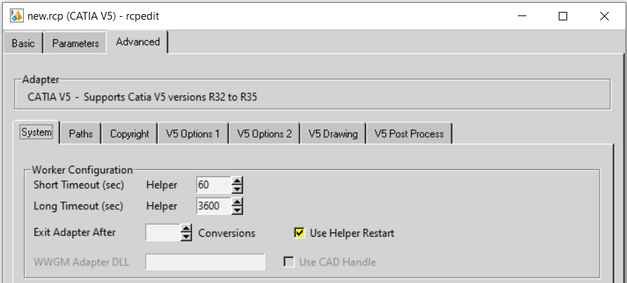
Apply an appropriate time for the Short and Long timeout (in seconds).
Note! These times are totally dependent upon the user data. Some trial and error may be required to define the best times for a specific user environment.
Worker Logs – To aid tracking of problematic crashes an environment variable has been added:
set TS_V5_CV_DEBUG_DUMP_GCO_DATA=1
will create a C:\TEMP\TS_DUMP_V5_PV.vwr (ascii) just prior to the write code commencing. This should only
be used under support supervision and recommendation.
CATIA V5 Configuration
This section details how to define and configure the CATIA V5 and SpinFire Convert environments to work together.
Conventions
Release of CATIA V5 – To indicate a release of CATIA V5 the notation <XX> shall be used. This needs to be replaced with the specific release to be used i.e. 32, 33, 34, 35 etc.
Platform specific directory – Within the installation directory of CATIA V5 there is a platform specific directory i.e. win_b64. This directory shall be referred to as <OSDS> in this Appendix.
SpinFire Convert Installation directory – The SpinFire Convert translator installation directory is set during the install process and is subsequently displayed in the ts_env.bat file after the install has been completed. This directory shall be noted as <%TS_INST%> in this Appendix.
CATIA V5 Installation Directory
Upon installation of a CATIA V5 product the user will be asked to specify the installation directory. This is the directory which contains the platform specific <OSDS> directory.
Having selected the CATIA V5 installation directory via the browse button, the installation process will record the location of the CATIA V5 installation directory in the ts_env.bat file. This file is located in the SpinFire Convert translator installation directory. If the location of CATIA V5 subsequently changes, the translator can be guided to the changed location by modifying this file using a text editor.
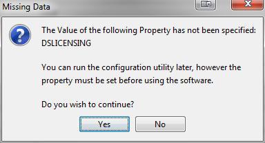
If no entry is included for DSLICENSING a warning dialog will be displayed which warns of the empty field. Selecting Yes to continue will allow the installation to continue.
Running CATIA V5 Translators
Before running the translator, the user must run CATIA V5 interactively at least once to configure the CATIA V5 environment and license settings. This can be achieved by running the catia5r<XX>_start script as follows:
%TS_INST%\bin\catia5r<XX>_start.cmd
Once CATIA has been run the Translator can run as described in the relevant product User Guide sections.
CATIA V5 Environment DIRENV & ENV
The default location for CATIA V5 to store its global environment files is in:
C:\ProgramData\DassaultSystemes\CATEnv
Or
%APPDATA%\CATEnv
You can find this location by running:
%CATIAV5_INST%\<OSDS>\code\bin\setcatenv -h
The environment files are named in the form CATIA.V5RN.B<XX>.txt. If when installing CATIA V5 the default environment file location was replaced with another location then this location needs to be indicated to the translator by defining in the ts_env.bat the environment variable CATIAV5_DIRENV:
set CATIAV5_DIRENV=/some/directory
If the SpinFire Convert installation is needed to support multiple releases of CATIA. Then the user can define release specific locations using:
set CATIAV5R<XX>_DIRENV=/some/directory
The SpinFire Convert translator will attempt to create its own environment file called TheoremCatia5R<XX>.txt. The user must therefore have write permissions to the CATEnv directory. If this is not possible an existing environment file can be specified using the variable CATIAV5_ENV. e.g.
set CATIAV5_ENV=CATIA.V5R32.B32
Note. the extension .txt is not required. The user can specify a release specific name using CATIAV5R<XX>_ENV e.g.
set CATIAV5R19_ENV=CATIA.V5R32.B32
Checking the CATIA V5 Environment
A script is provided to check that the CATIA V5 environment is set up correctly. In a command prompt window run the command script:
%TS_INST%\bin\checkcatia5r<XX>env.cmd
SpinFire Convert Configuration File (ts_cfile)
There are a number of optional pieces of information that can be provided to the Adapter prior to execution. These will control the information that is finally written into the output Creo View file by selecting specific data to be read from the input files processed.
These options are controlled by settings defined within the CATIA V5 Creo View Adapter configuration file (ts_cfile). To invoke these controls, it is necessary to create the configuration file and also set the configuration filename and location.
Configuration File Format
The configuration file is a simple ASCII text file generated with any available text editor. The format of the file is such that each configuration command statement is specified on a separate line. Blank characters separate any optional arguments related to the configuration command statement. e.g.
progress_file c:\TEMP\v5_pv.log
pmi_RGB 000-000-000
Configuration File Location
The location of the configuration file can be defined in one of 2 ways. The recommended method is to use the recipe editor. See V5 Options 2 – More translation settings, Additional Options file.
Alternatively, the ‘TS_CFILE’ environment variable can be set to point to the CATIA V5 Creo View configuration file prior to starting the translation Adapter:
Syntax: set TS_CFILE=<configuration_filename>
e.g. set TS_CFILE=C:\TEMP\configuration.txt
Drawing Processing Options
The following table shows the effect of the combined CATIA V5 Tool->Options and the CATIA V5 Creo View Adapter recipe settings:
Drawing Type |
V5 save single file |
PV Multi-File |
Comment |
|---|---|---|---|
DXF |
Enable/Disabled |
Enabled/Disabled |
Multiple .dxf files are always created for this file type – OK |
CGM |
Enabled |
Enabled/Disabled |
Single .cgm file with multiple sheets – OK |
CGM |
Disabled |
Enabled/Disabled |
Single .cgm file with single sheet – Not OK |
TIF |
Enabled/Disabled |
Disabled/Enabled |
Single .tif file with single sheet – Not OK |
Disabled |
Disabled |
Multi .pdf files created but only first sheet is viewable – Not OK |
|
Disabled |
Enabled |
Multi .pdf files with a sheet per file – OK |
|
Enabled |
Disabled |
Single .pdf file – correctly displayed with multiple sheets – OK |
|
Enabled |
Enabled |
Single .pdf file displayed as individual pages from same file – OK |
|
HPGL |
Disabled |
Disabled/Enabled |
Single .hpgl file created with only first sheet – Not OK |
HPGL |
Enabled |
Enabled/Disabled |
Single .hpgl file created with multi sheets – OK |
SpinFire Convert Support Advanced Options
The following environment variables are available to modify the Adapter’s behaviour under the guidance of the SpinFire Convert support team.
It is recommended, under guidance from the SpinFire Convert Support team that these variables be set in the ts_env.bat file, if required.
Where no value is suggested, set the variable with a value of 1:
e.g. set TSC_DEBUG_TIME=1
Diagnostics
Variable |
Value |
Description |
|---|---|---|
TSC_DEBUG_TIME |
1 |
Annotates logs and screen output with time stamps. The Diagnostic Logs -> Info recipe setting must be on. |
TSC_DEBUG |
1 or 2 |
Annotate logs and screen output with debug data. Note! Much of the TSC_DEBUG info is now re-directed via the |
TSC_EXT_REF |
1 |
Output specific debug for external references. |
TSC_LEAVE_GCO |
1 |
Retain any intermediate GCO files. |
Filtering
Variable |
Value |
Description |
|---|---|---|
TS_NO_ROUGHNESS |
1 |
Disable PMI roughness types. |
TS_OMIT_ATTRIBUTES |
1 |
List of attribute names to be omitted. |
TS_DISABLE_OMIT_ATTRIBUTES |
1 |
Allow all attributes through. |
Options
Variable |
Value |
Description |
|---|---|---|
TSC_EXT_REF_ASSY |
1 |
Include Assemblies as an external reference set. |
TSC_DISABLE_LARGE_ASSY_PARTS |
1 |
For large assembly processing, omit geometry processing. |
TS_DISABLE_PRIMSOL_WR |
1 |
Disable the ability to write GCO PRIMSOL data (CATIA V4 pipes). |
TS_CFILE |
1 |
Import general command line options via a file input. |
Representations
Variable |
Value |
Description |
|---|---|---|
REPRESENTATIONS |
Causes all representations for a node to be read. |
|
REPRESENTATION |
<Name> |
Causes the named representation for a node to be read. If this does not exist, then the default representation will be read. |
Positional Assembly Testing
This is a special set of options used to test positional assembly outside of Windchill, and possibly provide some control on its behaviour, these options offer NO benefits for end users.
Variable |
Value |
Description |
|---|---|---|
TS_TEST_POSITIONAL_ASSY |
1 |
Simulate Positional Assembly mode in Windchill. |
TS_TEST_WORKER_MODE |
1 |
Simulate Worker Mode in Windchill. |
TS_POSITIONAL_ASSY_DEPTH |
1 |
Allow the depth of the read of positional assembly to be adjusted. |
TS_CATPRODUCT_IGNORE_FALLBACK |
8-bits |
001 – Ignore REFASSYNAME check. 010 – Ignore signal event check. 100 – Ignore NETS=0 check. 111 – All on. |
JT Configuration File
When saving JT files, a default JT configuration file will be used. If the user wishes to specify a different configuration file then this is achieved by setting the environment variable:
set TS_WCV_JT_SAVEAS_OPTIONS=-z %TS_INST%\etc\tessSomeOther.config
Note! The -z <config file> syntax
The additional options field can also be used in the recipe editor to specify a JT configuration file via:
-z <full path to JT config file>
Alternate File Format (Additional File Types)
When JT is selected as an alternative file format using the JT Add On module, the JT configuration file allows the output name to be sanitized.
Some characters are invalid in a JT context and need to be changed during the translation process. The Adapter is shipped with a default set of characters to be mapped to the allowable character of “_”. These characters are:
\n\r\t`~!@#$%^&*()-+="\\':;,. /<>?|[]{}
It is important, particularly in a Windchill context, that the resultant JT file can be found, as it will need to be in a .pvoa file.
This string of invalid characters used by the JT Add On can be set by the user, via the environment setting:
set TS_V5_CV_JT_INVALID_CHARS="\n\r\t`~!@#$%^&*()-+="\\':;,. /<>?|[]{}"
This string would have to mirror the Filter>FilenameSanizationSet value in the JT config file. It is suggested that the SpinFire Convert support team should be contacted in the unlikely event that this is used.
Restart
When the Adapter is used in a Windchill context, in some circumstances the worker process may require a restart. For example, when there are no CATIA V5 licenses available. This behaviour can be enabled by a recipe setting:
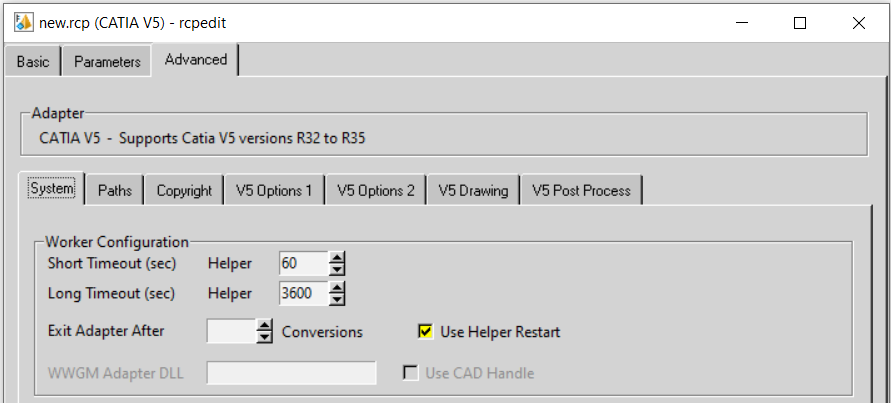
In addition to the recipe setting an environment variable setting is required to ensure that the end-user deliberately wants to switch on the restart functionality.
Variables can also be set to run a user defined script that can carry out specific actions at the time of restart, e.g. stopping other processes and cleaning temporary directories.
Variable |
Value |
Description |
|---|---|---|
TS_CREOVIEW_RESTART_CONFIG |
1 |
Switch on Windchill Restart |
TS_V5_CV_RUN_STARTUP_SCRIPT |
<name> |
The name of a script that is run by the catiastart.bat script when the worker is restarted |
TS_V5_CV_TEMP_CACHE_DIR |
<dir> |
Folder to delete when the worker is restarted |
PMI Options
If flat to screen or flipped PMI is enabled then the PMI nodes may be split between the PMI and leader data. In these cases, PMI and Leader nodes are by default associated so that if the PMI text is selected, so is the leader. This can be disabled via the environment variable:
TS_V5_CVW_PMI_PMI_OMIT_LEADERS=1
Screen Output
By default, error messages are reported to a temporary log file:
%TSC_TEMP_DIR%\ts_v5_pv_stderr.log
Error messages can be redirected by setting the variable below:
Variable |
Value |
Description |
|---|---|---|
TS_OUTPUT_STDERR |
1 |
Redirects error messages to the screen log, or a log specified via the –vL command line argument |
Worker Logs
If -vm <level> worker logs are enabled and not re-directed to a log file, then these messages will default to
stderr and be written to the ts_v5_pc_stderr.log.
Animation Files
Motion file units can be specified:
Variable |
Value |
Description |
|---|---|---|
TS_MOTION_FILE_UNIT |
m, cm, inch, feet, yard or value |
Specify a unit or a value. where value is mm/unit required |
PVZ Output
PVZ output can be enabled by setting the recipe editor option:
adapter/outputPvz=1
Issues Creating a CATIA V5 Worker
In the unlikely scenario that the recipe editor displays the create catia5Worker button greyed out then it is
necessary to run the %TS_INST%\bin\pview.reg file. This updates the registry and will enable this button to
be selected.
Managed CGR (aka SuperCGR)
Managed or SuperCGR (PTC terminology) is the capability provided via the Adapter to allow a CGR file to be created for the CATPart or CATProduct at the same time as generating the Creo View output data.
This capability is the forerunner to the Post process SaveAs capability, so it is only used by a few customers. The function is switched on via a hidden recipe file setting:
adapter/output_CGR=my_cgr_file_name
This will result in a file being created in the Creo View output directory named my_cgr_file_name.cgr
Alternatively, adapter/output_CGR= will result in a file being created in the Creo View output directory named
after the input CATPart/CATProduct file name.
For customers using Managed CGR, this Adapter setting is set by the Windchill worker mechanism.
When processing assemblies the output will always be a single CGR file.
An additional option can be used to provide an alternative output directory for the generated CGR files. A FULL path when using this option:
adapter/output_CGR_Path=C:\\TEMP\\target_cgr_output_path
Note! Double back slashes are required for Windows paths.
Tessellation Settings
In the unlikely event that a user should want to alter the tessellation settings in the Creo View output, the following settings can be manually added and modified in the recipe file under guidance from your PTC representative:
adapter/lod=Standard and adapter/chordHeight=0.1 would result in a higher level of tessellation, so consequently a larger file is produced.
adapter/lod=Standard and adapter/chordHeight=10.0 would result in a lower level of tessellation,
so consequently a smaller file is produced.
Instance Naming
Variable
Value
Description
INSTANCE_NAMING
V5
This advanced argument causes the part names in Creo View to be displayed in accordance with the Tools->Options->Infrastructure->Product Structure->Nodes Customization panel.
INSTANCE_RENAMING
<STRING>
Allows this to be specified on the command line. Details of the options are shown below.
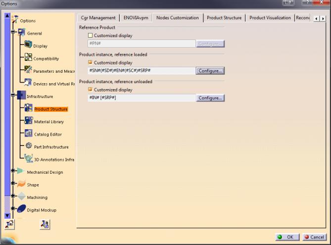
An example naming configuration is shown below
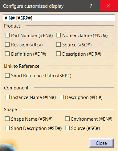
The code looks for the #XX# type string, finds the appropriate attribute and replaces it in the string.
Note that care should be taken when assigning these names as you can end up with both duplicated names and/or empty names.
Support for renaming the instance on the command line is available when using the option
INSTANCE_RENAMING <string>, where <string> (#XX#) can be a combination of
Product,
#PN# - Part Number,
#NO# - Nomenclature,
#RE# - Revision,
#SO# - Source,
#DF# - Definition,
#DR# - "Description",
Link to Reference,
#SRP# - Short Reference Path,
Component,
#IN# - Instance Name,
#DI# - Description,
Shape,
#SN# - Shape Name,
#EN# - Enviroment,
#SD# - Short Description,
#SC# - Source
Setting it to V5 will replicate the naming style from the CATIA V5 CATSettings.
Flat to screen OR flipped PMI
If these are enabled the PMI nodes are split between PMI and leader data. This can be disabled via:
TS_V5_CVW_PMI_PMI_OMIT_LEADERS=1
What’s New
What’s new in 24.0
Flexible Assembly Visualization
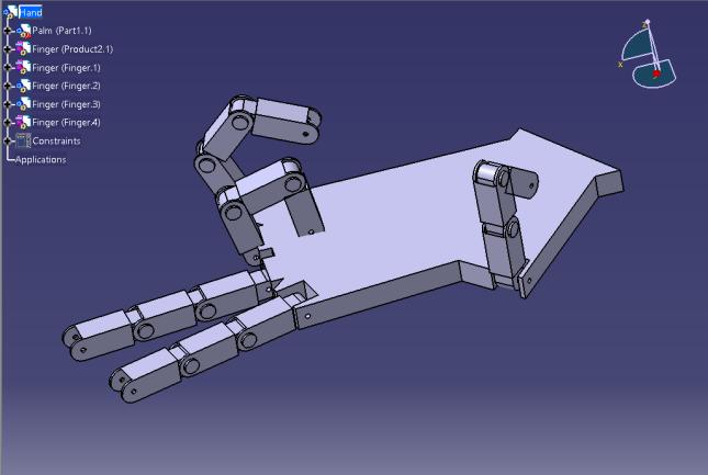
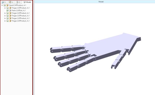
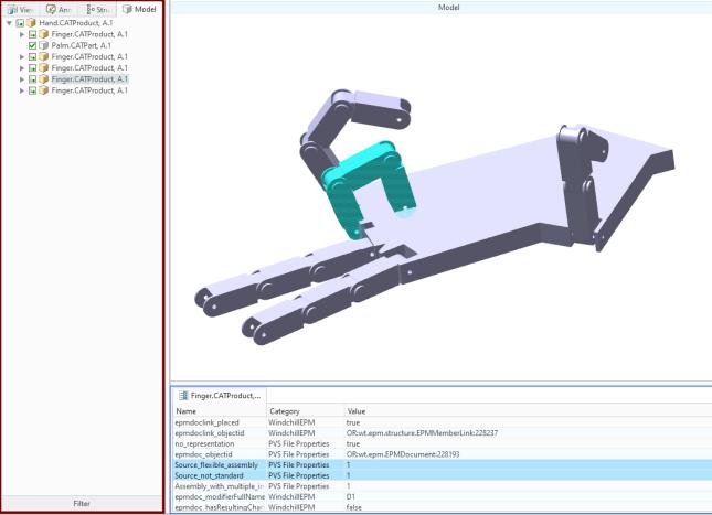
This release allows the end-user to make use of Flexible Assembly Visualization in Windchill. This behaviour is turned on by default in the translator.
Flexible assembly shown in CATIA V5 |
|
Display in Creo View when value for “Flexible assembly features in Dynamic CAD Structures” is set to “No” |
|
Display in Creo View along with attributes, when value for “Flexible assembly features in Dynamic CAD Structures” is set to “Yes” |
|
Multi Body Components
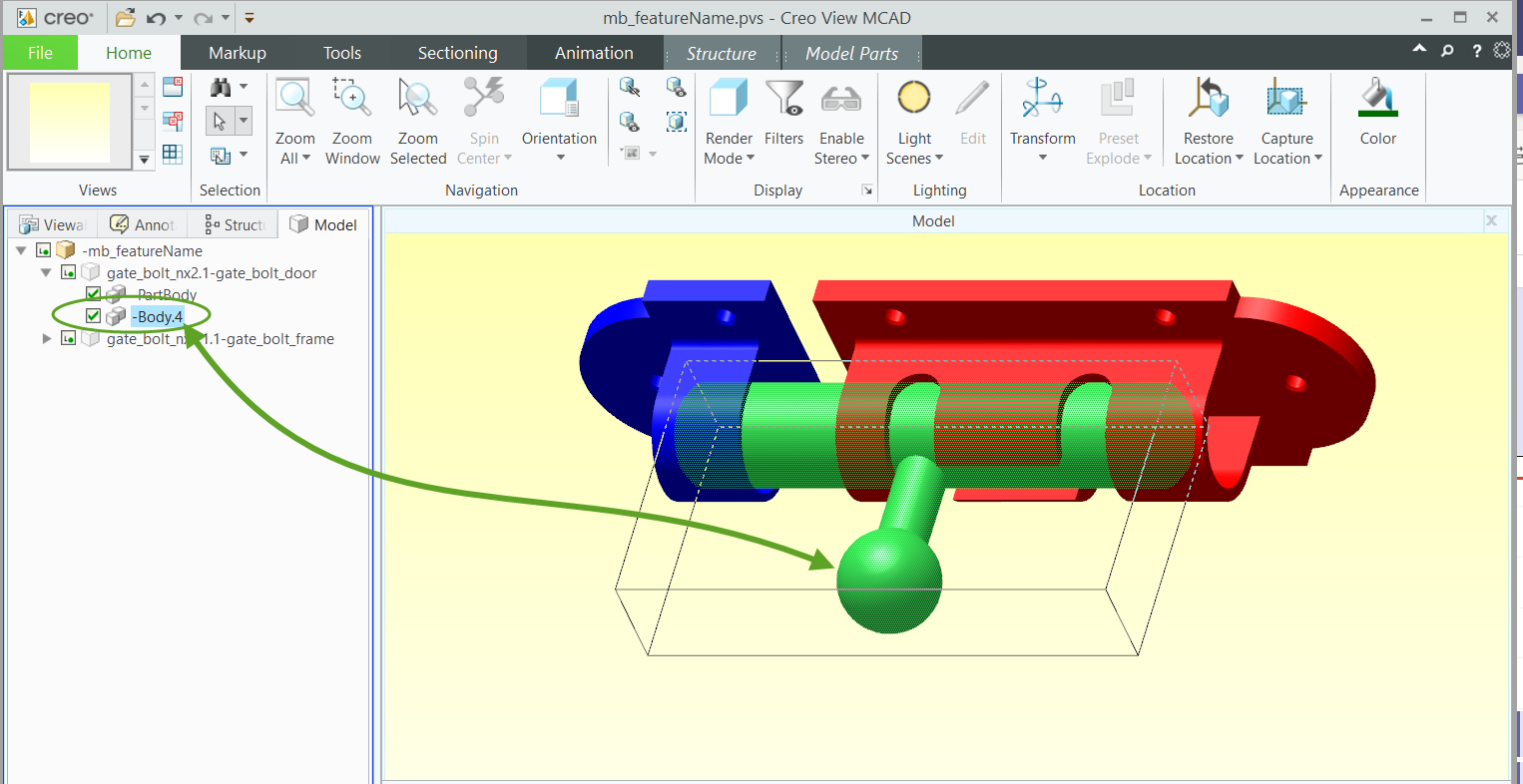
Multi-body components are now supported in Creo View and the translator takes advantage of this. The expand_part functionality will be replaced by this multi-body support and is turned on by default. If this is not required it can be turned off in the recipe file using the ‘Disabled’ option. For version 28.0 the default option has been changed to ‘Parts’ instead of ‘Enabled’.
Each body will be shown with a new icon and can be individually addressed.
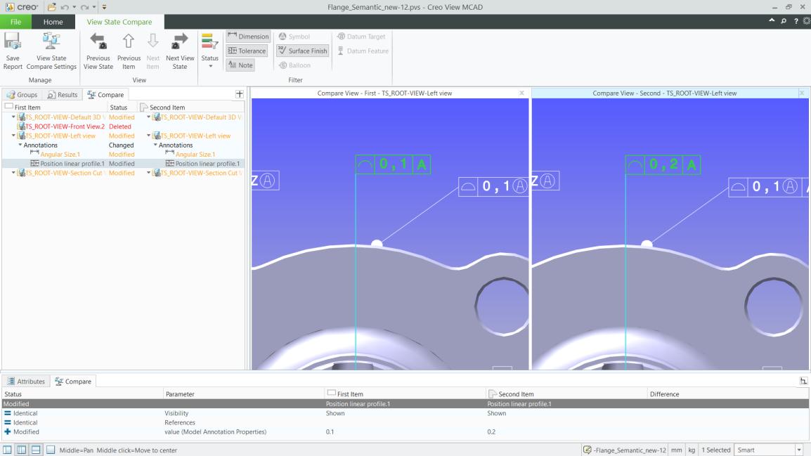
View State Comparison
A new Creo View tool, View State Comparison allows the PMI in each View State (CATIA Capture) to be compared, when two revisions of the same part are open.
A simple visual report of the two part revisions is clickable to allow each modification to be examined in more detail.
Further details of the View State Comparison tool can be found in the PTC Creo View documentation.
What’s new in 24.2
Tessellation now uses default bounding box functionality
This release has moved the default tessellation strategy closer to that of PTC. The tessellation is based upon the solid and surface geometry bounds. In most cases, better or equal results have been observed when compared with the previous revision. If there is any degradation in the tessellation in your particular case, please contact the support desk who will be able to help.
Materials and mass properties are read by default.
Materials and mass properties are now read by default when available. This will give more accurate mass property results in Creo View for single body and multibody components. Material properties only include colours but not texture maps. i.e. a material such as gold will have its colour mapped, whereas a material texture such as honeycomb will not.
Material visual properties (colour, opacity) are read.
Inheritance is also in place for multi-body components. At present the translator assumes the CATIA default, which is to propagate the material down to the lower level bodies. See examples below:
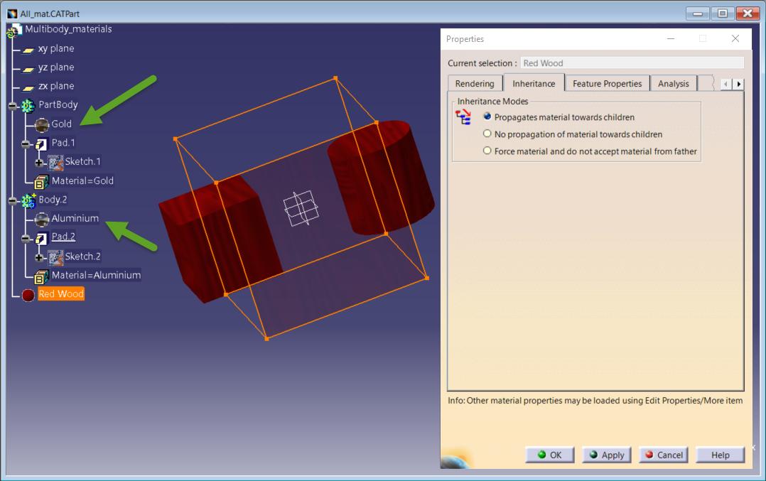
In the above example, because Red Wood has a texture map applied then the translated output will be the default body colour. However the Part level mechanical properties will be correctly washed down to the lower level bodies.
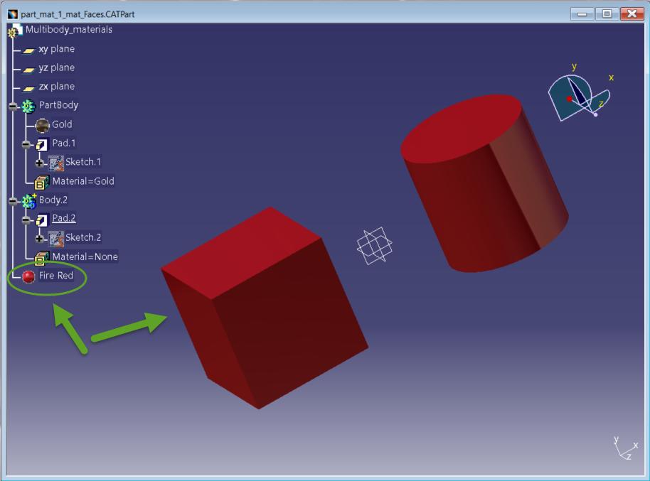
If a material with a colour, such as ‘Fire Red’ is applied then the colour will be translated as well as the mechanical properties.
Recipe File Changes
The Mass properties check box has now been removed from the V5 Options 1 tab of the Recipe Editor as this is now the default.
What’s new in 25.2
CGR Structures
CGR structures are now displayed consistently in both Standard and Minimum Memory mode.
Enhancements to Material properties
There is now a button to override the material color rendering. This new option is named Material Render. See image below:
What’s new in 25.4
Windchill Smart Platform Support: Locator Conversion
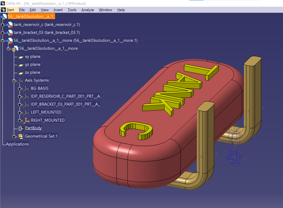
Starting from Theorem 25.4.01 and WWGM 12.1.2.0 (Narwhal), it is possible to expose Locators information from CATIA V5 Adapter to Windchill for positioning visualization. These locators are used to position model variants within an assembly in Windchill.
In CATIA V5 a Locator is a ‘named’ Axis System, for example ‘LEFT_MOUNTED’ or ‘RIGHT_MOUNTED’ as displayed in the example below:
The process is then activated by setting two ‘Filters’:
File Filter
This allows the user to limit the parts which the translator will read to search for locators. This filter only applies to top level CATParts. The translator will not attempt to search lower-level parts for locators. This is important if the data is large with a flat structure as without this limitation many parts without locators will be read.
The filter will allow a single asterix anywhere in the root string e.g. Skel* will find both Skeleton.CATPart and Skeleton_loc.CATPart or Skel*loc will only find Skeleton_loc.CATPart.
Multiple parts can also be specified but these must be the full name e.g. Skeleton,Loc but not Skel*,*Loc.
File Locator Filter
Multiple definitions can be in a comma separated list e.g., *TOR,L*3
This will now allow a single asterix anywhere in the root string e.g., LOC*, *TOR or L*R will find a locator called LOCATOR.
Recipe File Changes
The two filters have been added to the recipe file as shown below.
There are currently some known limitations.
It is not possible to convert axis systems to locators using Minimum Memory mode.
Publishing fails for a Product that contains an empty (without sketches or features) skeleton part.
Users should set Additional Options to NOSHOW_AXIS (see below) on Worker Server to be able to expose hidden axis systems or axis systems with hidden references.

Locator Filter and Locator Part Filter options do not recognize multiple ” * ” wildcard characters in their values.
Deactivated axis system can be exposed to Windchill if its value matches the Locator Filter option.
What’s new in 26.0
Quick View
QuickView for large assemblies is now available. Please refer to PTC article CS381237 for further information.
What’s new in 26.3
Multi-Body Parts and Materials
A reminder that the defaults for translation have changed over the last couple of revisions. Multi-body components are now read/created by default. This can be disabled in the recipe settings.

Materials are now read by default; the translator will also try to render the Creo View output using the CATIA material attributes. This can affect the face colour display in the Creo View output. It is possible to turn this rendering off, so that body and face colours are rendered instead. Toggle off Material Render for this to be applied.
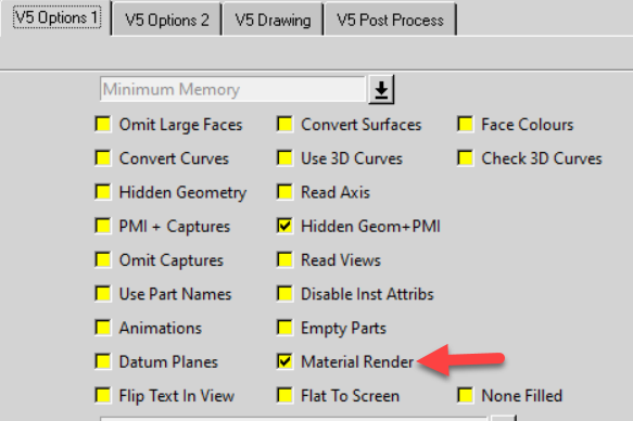
The translator will now always try to create mass properties for each body in a CATPart. For some parts (e.g. solids which have degraded to faces or a mixture of solids and surfaces) this can take a very long time without providing a useful mass properties result.
A new option MPROPS_OFF has been introduced to allow translation to take place more quickly.
Locators
A number of additional options/enhancements are now possible when using locators:
Multiple Wildcards “*” are now recognised in Locator Filter and Locator Part Filter e.g. *LOC*
Deactivated axis systems are no longer exposed as locators
Empty skeleton Parts now publish successfully
What’s new in 27.2
Conversion Mode
Default option for conversion mode set to ‘Standard’ replacing ‘Minimum memory’. Minimum Memory mode also deprecated in this version with this ultimately being removed in future releases.