User Guide
Using the Product
The CATIA V5 ↔ JT MultiCAD CADverters can be invoked in a variety of methods, these include;
Interactively from within CATIA V5 using standard CATIA V5 menu options such as “Insert Existing Component”, “File > Save As” and “File > Open”
From the Theorem UI
From a command prompt window using the command line. This mechanism can be used to automate the translation process as part of any automated workflow.
Interactive usage within CATIA V5
Starting CATIA V5
In order to use the Theorem CADverter products interactively within the CATIA application, you must start CATIA V5 with the correct CATEnv environment settings. A desktop icon and a start menu item are both able to be created during the installation process to achieve this.
The desktop icon is labelled “Theorem Multi-CAD JT CATIAV5RXX” (where XX is the release version (29 for V5-6R2019, 30 for V5-6R2020, 31 for V5-6R2021 & 32 for V5-6R2022).
The Start menu item is located under the “Start + All programs + CATIA” folder and is also named “Theorem Multi-CAD JT CATIAV5RXX”.
Options and Configurations
The CATIA V5 Multi-CAD architecture allows you to invoke the Theorem JT to V5 Multi-CAD translator to import components or assemblies into an active CATIA V5 CATProduct by using the “Insert > Existing Component…” menu item.
Also note that the CATIA associativity (Update Status Checker) mechanism can invoke the translator execution.
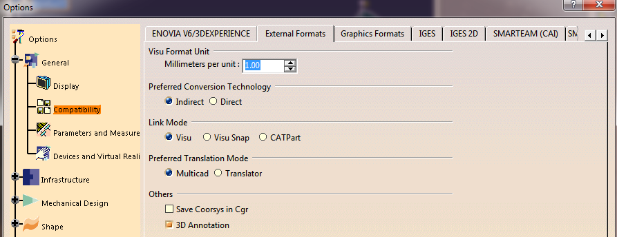
In order for the Theorem translator to be invoked from within CATIA V5, the setting of the “Preferred Conversion Technology” must be set to “Indirect” on the CATIA V5 Tools > Options > Compatibility > “External Formats” option page.
Note that this option page is only available if the TXX-THEOREM-MULTICAx GATEWAY (Theorem Partner) license is available which is provided by the Theorem license manager. Please see Setting Conversion Options in CATIA for a full description of these options.
There are some extra conversion options available to the Theorem User Interface that are not presented on the CATIA V5 External Formats options page.
One method to allow you to specify additional options to the JT to V5 Multi-CAD translator is provided by a configuration file that the translator reads during the conversion process.
The configuration file is named %TS_INST%\data\jt\jt_xcad_opts.txt and contains information on
the various options that can be specified using this method.
In addition a dedicated page of options for MultiCAD JT Import and Export operations is also available under the CATIA ‘Tools>Options>Infrastructure>Theorem’ menu and is presented as follows:
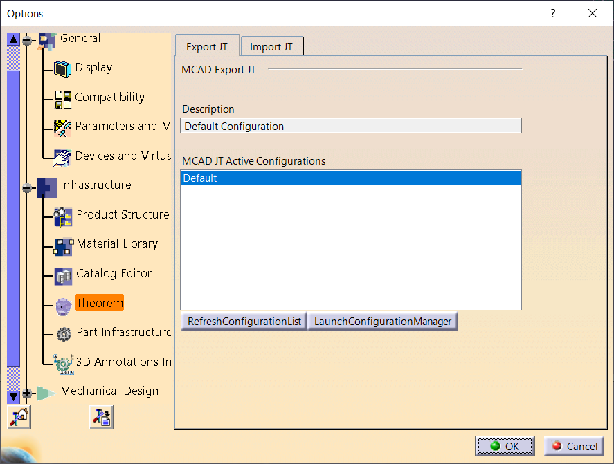
The ‘Export JT and ‘Import JT’ tabs both contain a list of Configurations used to process the JT data. To create or edit an existing configuration select the ‘Launch Configuration Manager’ option. This will launch the window below:
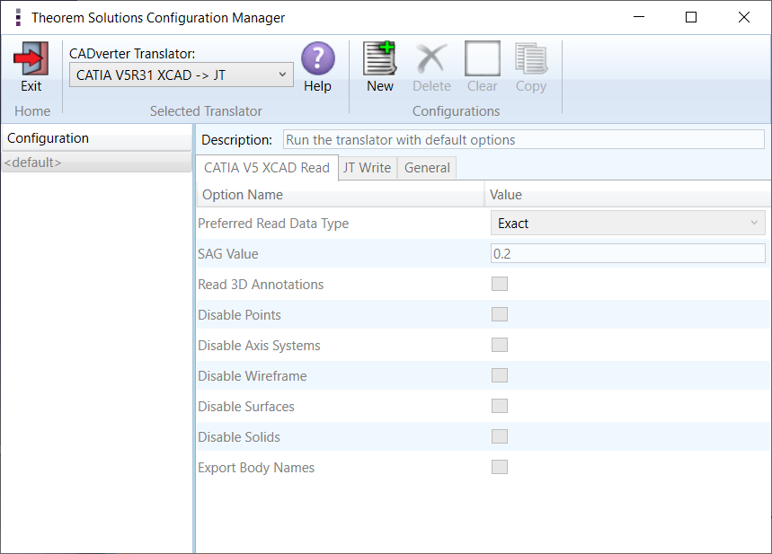
To create and choose options please review the Translator Customization section of this page.
Once the Configuration is completed close the Configuration Manager and select ‘Refresh Configuration List’ to show the new configuration(s).
To use a Configuration simply select it in the list and press ‘OK’.
Using “Insert Existing Component”
On invoking the “Insert Existing Component…” command in CATIA V5, and selecting a product node for the ‘insert’ operation, you will see the following file selector. The “JT Files” file type should be selected and a JT “.jt” file chosen
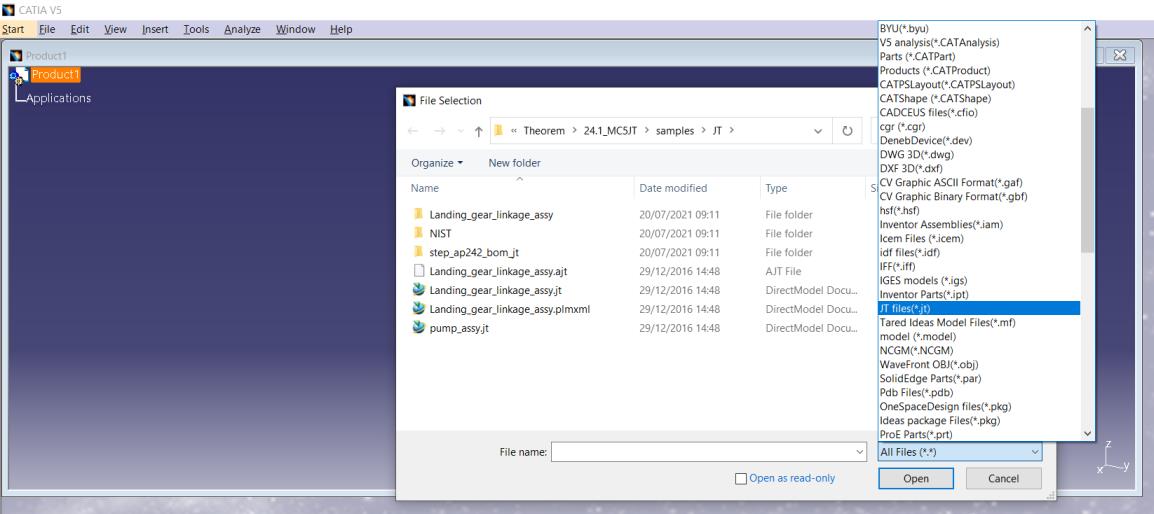
The translation will now proceed and the CATIA V5 representation of the JT assembly/components will be incorporated in the active CATProduct.
It is worth noting here that CATIA launches and manages a conversion sub-process that feeds the
option page settings into the Theorem Multi-CAD translator via a temporary file
named %CATTemp%\JTToNavConfigs.txt
This is referenced using the -c <config_file> command line option.
The Theorem User Interface allows you to select a CATIA generated configuration file as described
above, but if none is selected, a default configuration file installed with the Theorem software
under %TS_INST%\data\jt\JTToNavConfigs.txt will be used. For further information on the CATIA V5
Multi-CAD integration methods and commands see the CATIA Infrastructure Documentation.
The Theorem JT to V5 Multi-CAD translator is also invoked when the CATIA “Update Status Checker” command determines that a JT part file that was previously inserted using “Insert Existing Component” has been subsequently modified outside of the CATIA environment.
For further information on the usage of the CATIA commands “Insert Existing Component” and “Update Status Checker”, consult the CATIA Documentation under headings:
Mechanical Design -> Assembly Design
Here you will find topics - “Insert an Existing Component” - “User Tasks” -> “Updating an Assembly”
Visualizing Inserted Annotations
It should be noted that when you perform the “Insert Existing Component” command with a jt file containing PMI data, you must perform the following operations to visualise it if the Link Mode used is ‘Visu’ or Visu Snap’
Activate a workbench supporting FTA operations such as with menu item “Start > Mechanical Design > Product Functional Tolerancing & Annotation”.
Use menu “Insert > Visualization > List Annotation Set Switch On/Switch Off”
Enable the listed Annotation Sets and apply the change.
Using “File + Open”
The CATIA “File + Open” menu option allows you to select the file input type “jt”.
The translation will proceed and the CATIA V5 representation of the JT assembly/components will be opened in a new CATProduct window. This can be saved as a CATProduct.
Using “File + Save As”
The CATIA “File + Save As” menu option allows you to select the file output type “jt”. This will invoke the Theorem CATIA V5 to JT CADverter product using the selected CATPart or CATProduct node in the active CATIA session.
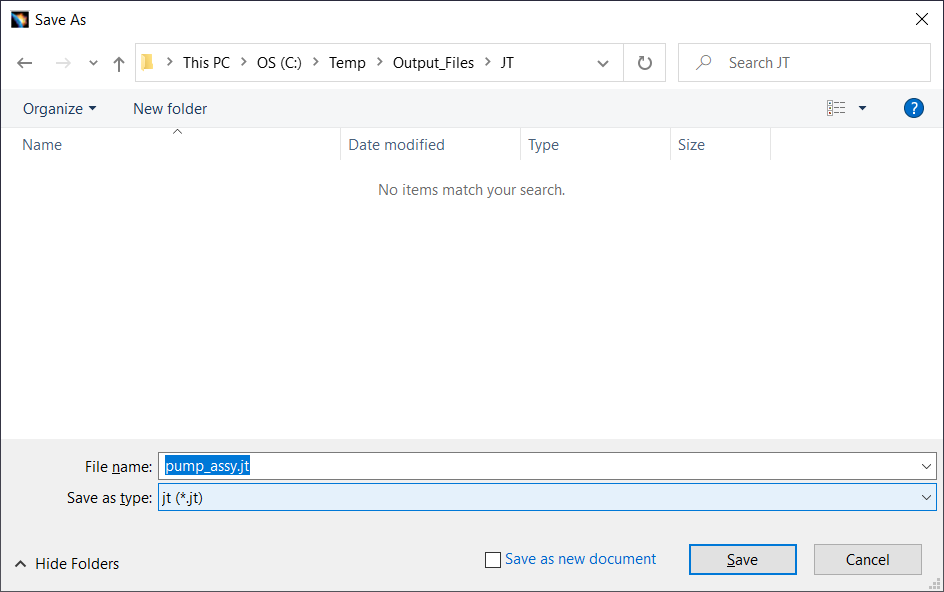
The CATIA V5 XCAD to JT processing messages, errors and warnings are recorded in a ‘.log’ file
located in the CATIA CATReport directory. The file is named after the active selected CATIA
part/product name. E.g. if the part/product Mypart were selected, the log file name would
be %CATReport%\Mypart.log.
A summary file is also produced which contains key information and the process completion status
information. It is named after then log file with the additional suffix .summary.
(e.g. %CATReport%\Mypart.log.summary).
The Data saved to JT format will export using the provided Configuration as seen on Page 10.
JT Configuration Files
The Theorem Multi-CAD product also allows the selection of a user defined, or Theorem provided, JT configuration file (.config)
- The default jt write configuration file is located as
%TS_INST%\etc\tessCATIA5MultiCAD.config
The options in the Configuration file are detailed in Property Mapping Files.
Property Mapping Files
The user can also manage the mapping of properties written from / to the JT file via a selectable JT property mapping file.
The default property mapping files are located in
%TS_INST%\data\jt\jt_v5_property_mapping.txt%TS_INST%\data\jt\v5_jt_property_mapping.txt
These text files contains information to show users how to implement a mapping process.
The contents of these option menus can be control by the specification of a jt_mcad_options_configuration.txt
file and example of which can also be found in the %TS_INST%\data\jt directory. To define a different file set
the environment variable TS_JT_MCAD_OPTIONS_CONFIGURATION
The format of the jt_mcad_options_configuration.txt is
<jt_config_files>
Default TessCATIA5MultiCAD;%TS_INST%\etc\tessCATIAV5MultiCAD.config
</jt_config_files>
<jt_import_property_files>
Default Import Jt Property Filter;%TS_INST%\data\jt\jt_v5_property_mapping.txt
</jt_import_property_files>
<jt_export_property_files>
Default Export Jt Property Filter;%TS_INST%\data\jt\v5_jt_property_mapping.txt
</jt_export_property_files>
There is one option menu entry per line with <Description> ; <Absolute File Path>
Where the <Description> is whats displayed in the option menu and the file path is the location of the jt write configuration file or the property filter. This path definition can include environment variables.
The user can control the mapping of user defined attributes contained in the CATIA product definition and external files during the import and export processes.
The ‘JT Import Property Mapping File’ and ‘JT Export Property Mapping File’ are text files of a format described as follows:-
A mapping file is used to control which properties are converted by setting a control value. Setting the control value to 0 will stop a specific property from being exported.
The mapping file can also enable the mapping of property names to new names: this is performed by switching the name between the input name (= field 1) and the output name (= field 2)
The File Line Format is as follows:-
SourceName, TargetName, Control, Dummy, Dummy, Dummy
Lines beginning with a “#” are taken as comment lines
SourceName – is the input attribute name.
TargetName – is the output attribute name (NULL means use SourceName)
Control – is flag to control conversion: 0 - Do not convert, 1 – Do convert
Dummy – unused fields
If SourceName is given as NULL then any item not included in map will match
So to include all other attributes use
NULL,NULL,1,,,
Or to exclude all other attributes use
NULL,NULL,0,,,
Examples
To exclude the MPARTNAME attribute
MPARTNAME,NULL,0,,,
To include the TAG attribute
TAG,NULL,1,,,
To rename the REFASSYTYPE attribute to ASSYTYPE
REFASSYTYPE,ASSYTYPE,1,,,
From the Command Line
The Theorem User Interface provides the ability to generate conversion command lines that are appended to a nominated batch file for subsequent execution.
%TS_INST%\bin\cad_run.cmd <translator_name>
-i <input_file_name>
-o <output_file_name>
[other options]
E.g. here is a command line example from a batch file:-
call "C:\Theorem\CAD_25.1_MC5JT_WIN.01\bin\cad_run.cmd" JT_CATIA5R32XCAD
-i C:\Theorem\ CAD_25.1_MC5JT_WIN.01\samples\JT\MyFile.jt
-o c:\temp\MyFile.CATProduct
mode_catpart
progress_file c:\temp\ progress.log > c:\temp\ screen.log 2>&1
The <translator_name> will take the form INPUT_OUTPUT as seen in the example above and is case sensitive. For this product the allowed inputs and outputs are
CATIA5R29XCAD
CATIA5R30XCAD
CATIA5R31XCAD
CATIA5R32XCAD
JT
So, to write JT data from CATIA V5-6R2021 (R31) the <translator_name> argument would be:
CATIA5R31XCAD_JT
To write CATIA V5-6R2022 (R32) data the <translator_name> argument would be:
JT_CATIA5R32XCAD
PLMXML from the command line
The command line version of the JT_CATIA5RxxxXCAD convert will also accept the Siemens proprietary .PLMXML file format for holding product structure data as the input file.
JT to CATIA V5 MultiCAD Usage
Setting Conversion Options in CATIA
If you have the TXX-THEOREM-MULTICAx license, the following categories of options will be visible from the CATIA menu - Tools > Options on the Compatibility “External Formats” page
Visu Format Unit
Preferred Conversion Technology
Link Mode
Preferred Translation Mode
Others
Output of generated data
Ideas®
ProEngineer®
Some of these settings are accessible to the Theorem CATIA V5 to JT Multi-CAD JT translator when it is run in both interactive and command line (batch) mode.
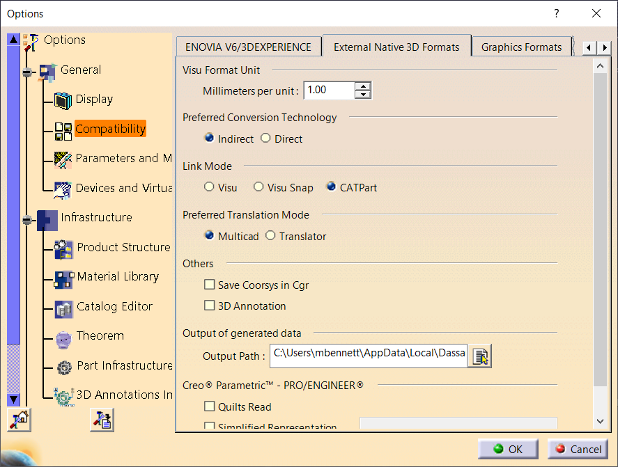
Visu Format Unit

- Millimeters per unit
The conversion of units from JT parts is incorporated into the Theorem CADverter, so this value should always be set to 1.00
Preferred Conversion Technology

Indirect
This parameter determines that the 3rd party Theorem converters will be used in conversion operations.
Direct
This parameter determines that the Dassault Systemes converters will be used in conversion operations.
Link Mode

Visu
Tesselated data. By default, this option is activated.
Visu Snap
Selecting this option forces the processing of JT precise BREP geometry to generate a CATIA V5 CGR output. In addition canonical shape properties are also generated in the CGR file. Consequently the CGR data resulting from importing JT will have additional geometry snapping capabilities. After selecting this option, this message appears: “Please, restart session to take modifications into account”.
CATPart
This option causes the import of exact/brep geometry from the JT file to be created in CATPart form.
Preferred Translation Mode

Selecting this option controls if links will be retained between the source jt files which are imported, and the resulting CATIA files generated. In Multicad mode, links are retained and modifications are locked, in Translator mode, links are not retained and modifications are allowed.
Others
Save Coorsys in Cgr
This option saves the JT PMI co-ordinate system data into the derived CGR representation when Visu output is selected. Note this feature would also require the 3D Annotation setting to be selected to create the required output.
3D Annotation
This parameter determines whether 3D annotation data, referred to as “PMI” data in JT, will be imported.
(Note, requires one of the following licenses):
Output of generated data

Output Path
Setting the Output Path location enables you to customize the folder location that is used when writing the derived CATIA V5 generated data. It specifies the location where CGR, CATPart and CATProducts will be generated.
The JT to CATIA V5 Multi-CAD options file
There are some extra conversion options available to the Theorem CADverter GUI that are not presented to the user on the CATIA External Formats options page.
A mechanism to allow you to specify additional options to the JT to V5 Multi-CAD translator is provided via a text file that the translator reads during the conversion process.
The default location of this options file is defined in the %TS_INST%\bin\TheoremProps.txt file by the
setting:
Theorem.JtServerCfile=%TS_INST%\\data\\jt\\jt_xcad_opts.txt
This text file can be edited to contain any of the following command line options on a separate line
Option |
Description |
|---|---|
info |
Outputs extra processing information to log files |
debug |
Outputs extra debugging information to log files help diagnose problems. |
diagnostics |
Outputs extra debugging information to log files to help diagnose problems. |
single_file |
If a JT assembly has mixed units, the user can use the ‘single_file’ option to force the JT data into a single intermediate representation file with any mirrored and scaled data being exploded out. This results in all unique instances of an assembly with different scales will have their geometry duplicated; with the correct scaling applied. If a monolithic JT assembly with mixed units is imported, this option is required. |
noprep |
This option effects the reading of XT-Brep data (embedded parasolid brep definitions) within the JT file. By default the brep data is prepared for writing to another system by steps such as removing small edges, splitting complex faces, and converting surfaces to. This option disables this preparation and uses the original parasolid definition. |
rd_native_edge |
By default some analytic edge definitions are converted to NURBS curves. This option forces the use of native analytic edge definitions. |
read_points / read_wire_frame |
By default, points and wireframe curve entities are not read from the JT file. If point entities are required, these options should be uncommented. |
read_pmi |
Overrides the CATIA Tools - options - Compatibility - “External Formats” “3D Annotations” CATIA setting to invoke read of PMI data. |
show_axis_system |
By default axis systems are created in CATIA hidden visibility space. This option will create them in the shown visibility space. |
The JT to V5 Progress and Log File Outputs
The JT to CATIA V5 XCAD process log and error messages are recorded in a ‘.log’ file located in the
CATIA CATReport directory. A process summary file is also produced here which contains the
completion status of the conversion. These files are named after the selected input file name. E.g. if
the file tea.jt were selected, the log and summary file names would be %CATReport%\tea.log
and %CATReport%\tea.log.summary.
If the JT to CATIA V5 XCAD process is run using the CADVerter GUI or using the command line option ‘progress_file’ <name>, the log file output will honour this name, and the summary file will be named similarly with the suffix ‘.summary’.
The V5 to JT Progress and Log File Outputs
The CATIA V5 XCAD to JT process log and error messages are recorded in a ‘.log’ file located in the
CATIA CATReport directory. The file is named after the selected output file name. E.g. if the file
Mypart were selected, the log file names would be %CATReport%\Mypart.log
and %CATReport%\Mypart.log.summary.
If the CATIA V5 XCAD to JT process is run using the CADVerter GUI or using the command line option ‘progress_file’ <name>, the process log and error messages will be output to the specified name, and the summary file will also be named after this name with the suffix ‘.summary’.
Using the Theorem User Interface
Default Translations
Default Translation – via the Unified Interface
The Unified Interface can be started via the Start Menu – if a shortcut was added during installation.
Alternatively, the Unified Interface can be run via a Windows Explorer selection in:
<UI_installation_directory>\bin\Unified_Interface.cmd
The following interface will be launched:
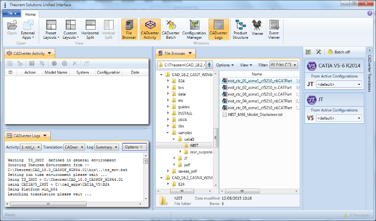
The default layout is split into 4 primary areas, which can be altered to the users prefer:
The simplest way to translate from CATIA V5 or JT is to drag a file from the file Browser Pane on to the Active Configurations for the translation you require.
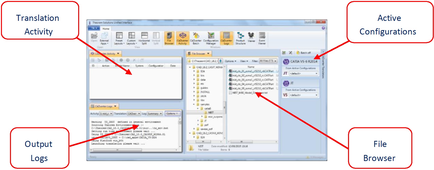

On completion, the Unified Interface will display the activity information and details from the log file created during the translation, if requested, in the Translation Activity and Output Log panes, respectively.
The generated output data can be located by selecting the translation from the Activity pane and opening the output folder:
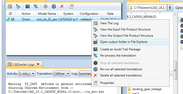
Default Translation – via Command Line Interface
Running a translation via the command line can be carried out via the cad_run.cmd file located in the <installation_directory>\bin directory. The format of the command is as follows when translating from CATIA V5 to JT:
<Translator_installation_directory>\bin\cad_run.cmd CATIA5R[XX]XCAD_JT -i <input_file> -o <output_file>
The format of the command is as follows when translating from JT to CATIA V5:
<Translator_installation_directory>\bin\cad_run.cmd JT_CATIA5R[XX]XCAD -i <input_file> -o <output_file>
(Note! Replace the [XX] seen in the example with the version of CATIA V5 you are using. E.g. for CATIA V5 R30, change to CATIA530):

The example above will translate a CATIA V5 sample file provided within the installation and will be output to the target location. In this case:
C:\TEMP\Rear_Suspension.jt
JT to V5 translations using the CATIA V5 Executable on Command Line
To run the translator from the command line you must ensure that the CATIA V5 environment is set correctly. The easiest method to achieve this is to use the standard CATIA start-up process. This uses the following syntax;
%V5_INSTALL_PATH%\win_b64\code\bin\CATSTART.exe
-run "%TS_INST%\B%V5_VER%\win_b64\code\bin\JTToNav.exe
%COMMAND_LINE_ARGUMENTS%"
-env Theorem_Multi-CAD_JT_CATIAV5R%V5_VER%
-direnv "%TS_INST%\B%V5_VER%\win_b64\CATEnv"
Where;
%V5_INSTALL_PATH% = the path to the CATIA V5 installation e.g C:\Program Files\Dassault Systems\v5r26\B26%TS_INST% = the path to the Theorem Solutions installation e.g. C:\Theorem\CAD_19.3_MC5JT_WIN.01%V5_VER% = the version of CATIA V5 that is being used e.g. 24, 25, or 26%COMMAND_LINE_ARGUMENTS% = these will depend upon the type of Link Mode data type that you want to create in the output e.g. VISU, VISU+SNAP or CATPartE.g. To translate a JT file to CATIA V5 to create the geometry in CATPart format and process PMI/FTA data the command line syntax would be;
e.g. %V5_INSTALL_PATH%\win_b64\code\bin\CATSTART.exe  -run
"%TS_INST%\B26\win_b64\code\bin\JTToNav.exe
-c %TS_INST%\data\jt\JTToNavConfigs_CATPart.txt
-i %TS_INST%\samples\jt\NIST\ nist_ctc_01_asme1_ct5210_rd.jt
-oproduct C:\temp\NIST_01.CATProduct -dpart C:\temp read_pmi"
-env Theorem_Multi-CAD_JT_CATIAV5R26
-direnv "%TS_INST%\B26\win_b64\CATEnv"
Using Link Mode: CATPart
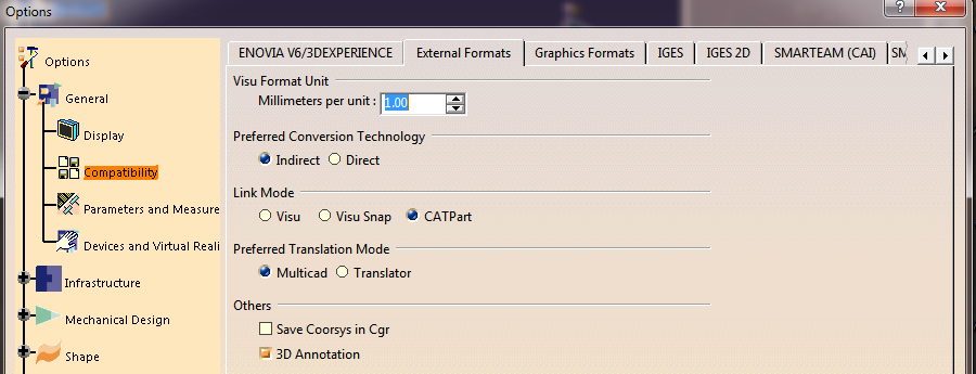
Command Line Arguments
-c %TS_INST%\data\jt\JTToNavConfigs_CATPart.txt-i <input_JT_filename>-oproduct <output_CATProduct_filename>-dpart <path_to_output_folder>read_pmi - optional argument to process JT PMI data. Note this requires access to a V5 FTA licensee.g :
-c %TS_INST%\data\jt\JTToNavConfigs_CATPart.txt -i %TS_INST%\samples\jt\NIST\
nist_ctc_01_asme1_ct5210_rd.jt -oproduct C:\temp\NIST_01.CATProduct -dpart C:\temp read_pmi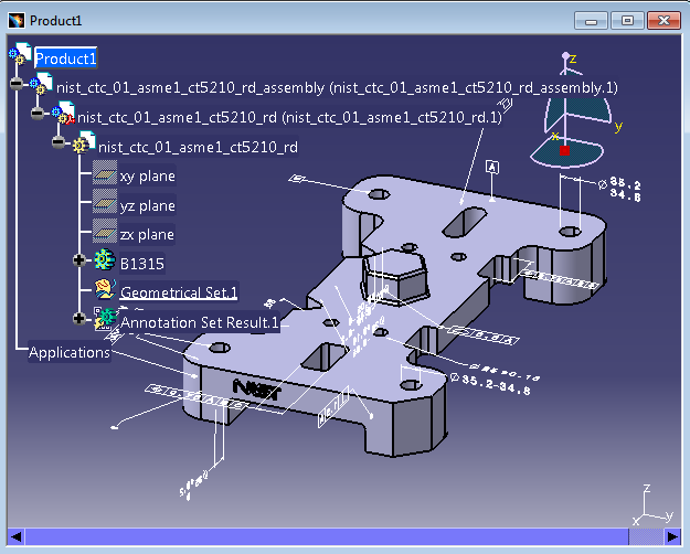
Link Mode: Visu Snap
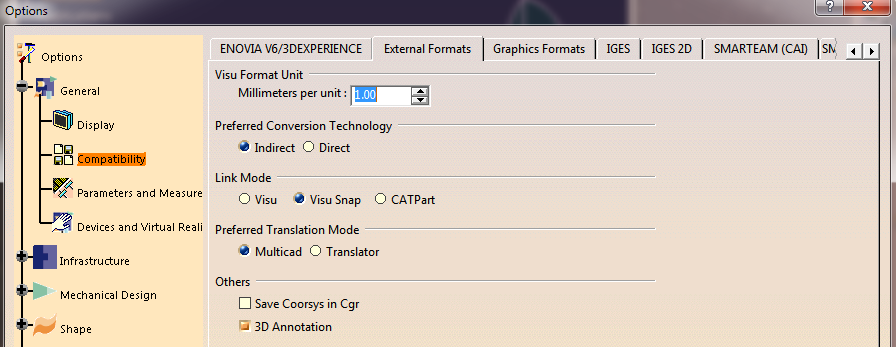
Command Line Arguments
-c %TS_INST%\data\jt\JTToNavConfigs_VISUSNAP.txt-i <input_JT_filename>-oproduct <output_CATProduct_filename>-d <path_to_output_folder>read_pmi - optional argument to process JT PMI data. Note this requires access to a V5 FTA licensee.g :
-c %TS_INST%\data\jt\JTToNavConfigs_VISUSNAP.txt -i %TS_INST%\samples\jt\NIST\
nist_ctc_01_asme1_ct5210_rd.jt -oproduct C:\temp\NIST_01.CATProduct -d C:\temp read_pmi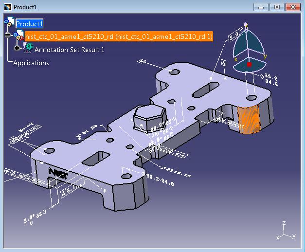
Link Mode: Visu
Command Line Arguments
-c %TS_INST%\data\jt\JTToNavConfigs_VISU.txt-i <input_JT_filename>-oproduct <output_CATProduct_filename>-d <path_to_output_folder>read_pmi - optional argument to process JT PMI data. Note this requires access to a V5 FTA licensee.g :
-c %TS_INST%\data\jt\JTToNavConfigs_VISU.txt -i %TS_INST%\samples\jt\NIST\
nist_ctc_01_asme1_ct5210_rd.jt -oproduct C:\temp\NIST_01.CATProduct -d C:\temp read_pmi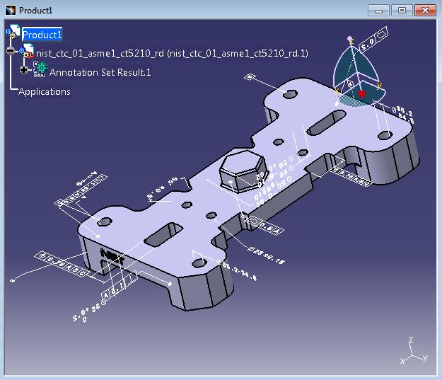
Translator Customization
The Theorem translator allows the information that is read from the source system and written to the target system to be tailored via a set of user specified arguments. Commonly used arguments are supported via the Unified Interface, with Advanced Arguments being described within this document for use in the Unified Interface or via the Command Line invocation.
Common Options for CATIA V5 to JT
Within the Configuration Manager pane of the Unified Interface, arguments that can be specified when publishing CATIA V5 data into JT are grouped into 3 areas:
CATIA V5 Read – Those arguments that affect how data is read from CATIA V5
JT Write – Those arguments that affect how the data is written to JT
General – Those arguments that are common to ALL Publishing activities regardless of source data
CATIA V5 Read Arguments
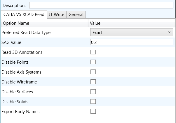
Option |
Description |
|---|---|
Preferred Read Data Type |
Allows the user to specify Exact or Tessellated read |
SAG Value |
Set SAG value |
Read 3D Annotations |
Read PMI |
Disable Points |
Disable the processing of standalone Points |
Disable Axis Systems |
Disable the processing of Axis Systems |
Disable Wireframe |
Disable the processing of standalone Wireframe |
Disable Surfaces |
Disable the processing of standalone Surfaces |
Disable Solids |
Disable the processing of solids |
Export Body Names |
Create Body Named Containers |
JT Write Arguments
The image below shows the Write JT arguments that are available, with their default settings:
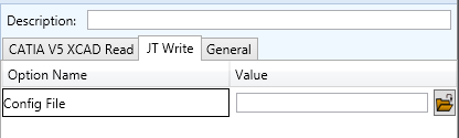
This option is described below:
Option |
Description |
|---|---|
Config File |
Allows a JT configuration file to be specified. Please see Property Mapping Files for a full description of the JT config file format. Command Line Syntax:
|
CATIA V5 to JT General Arguments
The image below shows the General arguments that are available, with their default settings:
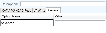
This option is described below:
Option |
Description |
|---|---|
Advanced |
Allows any of the Command Line Advanced arguments documented to be passed to the Unified Interface invocation. |
Exporting CGR Data to JT
When processing CGR files the default process will write a single JT “part” file for each CGR. However, it is
possible to expand the JT output such that an individual JT part file is created for each of the bodies in defined
in the original CGR file. To achieve this, use the command line options expand_part body_names. When using
the UI select the option “Export Body Names” in the CATIA V5 XCAD Read options and set the expand_part
option using the the Advanced option in the General options panel.
Common Options for JT to CATIA V5
Within the Configuration Manager pane of the Unified Interface, arguments that can be specified when publishing JT data into CATIA V5 are grouped into 3 areas:
JT Read – Those arguments that affect how data is read from JT
CATIA V5 Write – Those arguments that affect how the data is written to JT
General – Those arguments that are common to ALL Publishing activities regardless of source data
JT Read Arguments
The image below shows the JT Read arguments that are available, with their default settings:
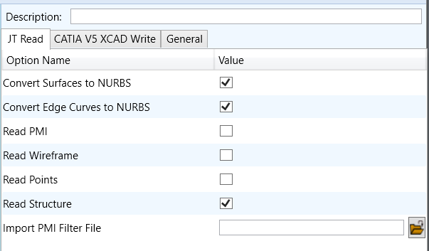
Each of these options is described below.
Option |
Description |
|---|---|
Convert Surfaces to NURBS |
Read XT Brep surfaces as NURBS surfaces (else read in native form). Default is ON. Command Line Syntax:
|
Convert Edge Curves to NURBS |
Read XT Brep edge curves as NURBS curves (else read in native form). Default is ON. Command Line Syntax:
|
Read PMI |
Reads 3D PMI. Default is OFF. Command Line Syntax:
|
Read Wireframe |
Read JT wireframe data. Default is OFF. Command Line Syntax:
|
Read Points |
Read Points. Default is OFF. Command Line Syntax:
|
Read Structure |
Read assembly structure. Default is ON. Command Line Syntax:
|
Import PMI Filter File |
JT Import PMI Filter File Name. Default is OFF Command Line Syntax:
|
CATIA V5 Write Arguments
The image below shows the CATIA V5 Write arguments that are available, with their default settings:
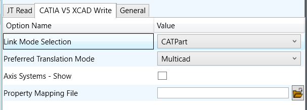
Each of these options is described below:
Option |
Description |
|---|---|
Link Mode Selection |
Choose the Link Mode to translate with (See Link Mode for details) Options are:
Command Line Syntax:
|
Preferred Translation Mode |
Choose the mode to translate with (See Translator Mode for details) Options are:
Command Line Syntax:
|
Axis Systems Show |
Show Axis Systems in output. Default is OFF Command Line Syntax:
|
Property Mapping File |
Specify a file which allows filtering of Detail user attributes. Default is OFF. Command Line Syntax:
|
JT to CATIA V5 General Arguments
The image below shows the General arguments that are available, with their default settings:
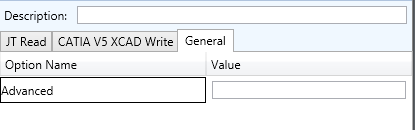
The option is described below:
Option |
Description |
|---|---|
Advanced |
Allows any of the Command Line Advanced arguments documented below to be passed to the Unified Interface invocation |
CATIA V5 Configuration
Introduction
This Appendix details how to define and configure the CATIA V5 and Theorem environment to work together.
Conventions
Release of CATIA V5
To indicate a release of CATIA V5 the notation <XX> shall be used. This needs to be replaced with the specific release to be used i.e. 29, 30, 31, 32.
Platform Specific Directory
Within the installation directory of CATIA V5 there is a platform specific directory i.e. win_b64. This directory shall be referred to as <OSDS> in this Appendix.
Theorem Installation Directory
The Theorem translator installation directory is set at installation time in the translator ts_env.bat file. This directory shall be noted as <%TS_INST%> in this Appendix.
CATIA V5 Installation Directory
Upon installation of a CATIA V5 product the user will be asked to specify the installation directory. This is the directory which contains the platform specific <OSDS> directory.
Having selected the CATIA V5 installation directory via the browse button, the installation process will record the location of the CATIA V5 installation directory in the ts_env.bat file. This file is located in the Theorem translator installation directory. If the location of CATIA V5 subsequently changes, the translator can be guided to the changed location by modifying this file using a text editor to modify the ts_env.bat that is located in the translator installation directory.
Running CATIA V5 Translators
Before running the translator the user must run CATIA V5 interactively at least once to configure the CATIA V5 environment and license settings. This can be achieved by running the catia5r<XX>_start script as follows:
%TS_INST%\bin\catia5r<XX>_start.cmd
Once CATIA has been run the Translator can run as described in the relevant product User Guide.
CATIA V5 Environment DIRENV & ENV
The default location for CATIA V5 to store its global environment files is in the global directory:
%APPDATA%\DassaultSystemes\CATEnv
You can find this location by running:
%CATIAV5_INST%\<OSDS>\code\bin\setcatenv -h
The environment files are named in the form CATIA.V5RN.B<XX>.txt
If when installing CATIA V5 the default environment file location was replaced with another location then this location needs to be indicated to the Translator by defining in the ts_env.bat the environment variable CATIAV5_DIRENV:
set CATIAV5_DIRENV=/some/directory
If the Theorem installation is needed to support multiple releases of CATIA. Then the user can define release specific locations using:
set CATIAV5R<XX>_DIRENV=/some/directory
The Theorem translator will attempts to create its own environment file called TheoremCatia5R<XX>.txt. The user must therefore have write permission to the CATEnv directory. If this is not possible an existing environment file can be specified using the variable CATIAV5_ENV. e.g.
set CATIAV5_ENV=CATIA.V5R29.B29
Note. the extension .txt is not required. The user can specify a release specific name using CATIAV5R<XX>_ENV e.g.
set CATIAV5R19_ENV=CATIA.V5R29.B29
Checking the CATIA V5 Environment
A script is provided to check that the CATIA V5 environment is set up correctly. In a command window run the command script:
%TS_INST%\bin\checkcatia5r<XX>env.cmd
JT Configuration File
Introduction
A configuration file contains the settings for your translations. The configuration file can be specified using the
command line option -config or -z.
If this is not supplied the following directories will be searched in the specified order for the named configuration files : (TS_INST = Installed directory)
tessCATIA5.config in the directory where the translator is runtess.config in the directory where the translator is runtessCATIA5.config in TS_INST\etc directorytess.config in TS_INST\etc directoryTwo example config files are provided in the TS_INST\etc directory, a standard tessCATIA5.config one, and one that illustrates the options required for large assembly processing, tessLargeAssmCATIA5.config which is documented by some comments within it.
The JT configuration file contains various sections, each containing different settings based on the section.
The Setup Section
The setup options in the configuration file define how your files are translated. The setup section is the first part of the configuration file and contains a series of standard translator options.
To edit setup options
Open an existing configuration file with a text editor.
Edit the configuration file options listed in the table below.
Save the configuration with a .config extension
Option name |
Keywords |
Example |
|---|---|---|
EAITranslator |
|
|
OutputDirectory |
“path to directory” |
|
CommonPartsPath |
“path to directory” |
|
chordalOption |
“RELATIVE” / “ABSOLUTE” |
|
structureOption |
“PER_PART” / “MONOLITHIC” / “FULL_SHATTER” |
|
WriteWhichFiles |
“ALL” / “ASSEMBLY_ONLY” / “PARTS_ONLY” |
|
compression |
true / TRUE / false / FALSE |
|
triStripOpt |
true / TRUE / false / FALSE |
|
seamSewing |
true / TRUE / false / FALSE (Note: Not available for Unigraphics.) |
|
seamSewingTol |
any integer |
|
includeBrep |
true / TRUE / false / FALSE |
|
brepPrecision |
“SINGLE” / “DOUBLE” |
|
autoNameSanitize |
true / TRUE / false / FALSE |
|
updateChangedPartsOnly |
true / TRUE / false / FALSE |
|
verboseReporting |
true / TRUE / false / FALSE |
|
writeAsciiAssembly |
true / TRUE / false / FALSE |
|
singlePartsNoAssem |
true / TRUE / false / FALSE |
|
smartLODgeneration |
true / TRUE / false / FALSE |
|
autoLowLODgeneration |
true / TRUE / false / FALSE |
|
numLODs |
any integer |
|
close brace |
|
|
The Level of Detail Section
The level of detail section of the configuration file contains the tessellation and simplification information for each level of detail in the file.
This section consists of several sets of level of detail (LOD) information, and the number of these sets depends on the number you specified on the numLODs line in the configuration file.
To edit level of detail options
Open an existing configuration file in a text editor.
Edit the configuration file options listed below.
Save the configuration with a .config extension
Option name |
Keywords |
Example |
|---|---|---|
LOD |
|
|
Level |
any integer |
|
Chordal |
any number |
|
Angular |
any number |
|
Length |
any number |
|
FeatureSuppression |
any integer |
|
Simplify |
any number |
|
close brace |
|
|
The Filter Section
The filter section of the configuration file contains the filename and metadata filtering information. Edit this section if you want to change how the translator sanitizes filenames and filters metadata keys.
To edit filter options
Open an existing configuration file with a text editor.
Edit the configuration file options from the table below.
Save the configuration with a .config extension
Option name |
Keywords |
Example |
|---|---|---|
Filter |
|
|
FilenameSanitizeSet |
“string of characters” |
|
FilenameSanitizeSetAdd |
“string of characters” |
|
FilenameSanitizeSetDelete |
“string of characters” |
|
MetadataKey |
“string of characters” |
|
close brace |
|
|
The Metadata Section
The metadata section sets which metadata to attach to all parts, assemblies and nodes of the model.
Note
Be sure to add these options to the configuration file in pairs: one line to define the metadata key and one line to define the metadata value.
To edit metadata options
Open an existing configuration file (.CONFIG) in a text editor.
Edit the configuration file options shown in the table below.
Save the configuration with a .config extension
Option name |
Keywords |
Example |
|---|---|---|
Metadata |
|
|
AddToParts |
“string of characters” |
AddToParts = "<metadata key>"AddToParts = "<metadata value>" |
AddToAssemblies |
“string of characters” |
AddToAssemblies = "<metadata key>"AddToAssemblies = "<metadata value>" |
AddToAllNodes |
“string of characters” |
AddToAllNodes = "<metadata key>"AddToAllNodes = "<metadata value>" |
close brace |
|
|
The Special Section
The special section of the configuration file contains lines that are unique to this translator.
To edit special options
Open an existing configuration file with a text editor.
Edit the configuration file options shown in the table below.
Save the configuration with a .config file extension.
Option |
Keyword |
Example |
Default Value |
|---|---|---|---|
Catia5Options |
|
|
|
ProcessSolids |
true / false |
|
true |
ProcessOpenSolids |
true / false |
|
true |
ProcessWireFrame |
true / false |
|
true |
ProcessPoints |
true / false |
|
true |
ProcessHiddenGeom |
true / false |
|
false |
ProcessLayers |
ALL_LAYERS / comma separated list |
|
ALL_LAYERS |
ReportFilename |
Full system file path |
|
C:%TEMP%\tscprogressyi |
OutputUnits |
mm / cm / m / inches / feet / yards / inputUnits |
|
inputUnits |
AppendCADExtension |
true / false |
|
false |
ProcessPMI |
read_pmi / read_pmi_1 / read_pmi_2 / read_pmi_3 / false |
|
false |
ProcessCaptures |
true / false |
|
false |
collapseHierarchy |
false / expandPart / SOLtoDetail / toSets / toPart / SURandFACtoDetail / toPartOptimized |
|
SOLtoDetail |
structureOutputType |
JT / PLMXML / PLMXMLJT |
|
JT |
brepType |
JT / XT / XTJT |
|
JT |
parasolidTolerantModelling |
true / false |
|
true |
parasolidTolerantModellingFactor |
An integer factor |
|
3 |
sewParasolidBodies |
true / false |
|
true |
sewParasolidBodiesTol |
A tolerance for sewing in millimetres |
|
0.01 |
incrementalSewing |
true / false |
|
true |
incrementalSewingNoOfIterations |
The maximum number of iterations to be used for incremental sewing |
|
5 |
explodeSolidsToFaces |
true / false |
|
false |
splitDiscontinuousSurfaces |
true / false |
|
true |
forceBodyCreation |
true / false |
|
true |
fixDegenerateEdges |
true / false |
|
true |
faceEdgeTol |
A tolerance for face creation in metres |
|
0.000006 |
fixSmallFeaturesSolids |
true / false |
|
false |
fixSmallFeaturesOpenSolids |
true / false |
|
false |
simplifyGeometry |
true / false |
|
false |
brepWireframe |
true (process wireframe as JT Brep) / false (process wireframe as tessellation) |
|
false |
produceTessellatedOutput |
true / false |
|
false |
expandPart |
true / false |
|
false |
reuseSolids |
true / false |
|
false |
cadPropertyMappingFile |
Mapping File for JT Properties |
|
Optional Config Entry |
addSemanticPMI |
true / false |
|
false |
JTBrepFixup |
true / false |
|
true |
PMIAttributeMap |
true / false |
|
false |
PMIAttributeMapFileName |
Mapping File for PMI Attributes |
|
Optional Config Entry |
externalDetailNaming |
Mapping File for detail names |
|
Optional Config Entry |
layerFilter |
true / false |
|
false |
defaultLayerFilter |
Layer Filter Name to be used as the default |
|
Optional Config Entry |
subNode |
true / false |
|
false |
retainAssemblyStructure |
true / false |
|
true |
readSpaceReservations |
true / false |
|
false |
readScanData |
true / false |
|
false |
readCachedCGR |
true / false |
|
false |
readLeafNodeCGR |
true / false |
|
false |
readHiddenData |
None / Geometry / Structure / All |
|
None |
viewContext |
Default3D / Unfolded |
|
Default3D |
readFaceColours |
true / false |
|
false |
faceOpacity |
true / false |
|
false |
opacityZero |
The value of opacity to be actually used when opacity is zero |
|
0.1 |
simplifyProgressFile |
true / false |
|
false |
convertCurvesToNurbs |
true / false |
|
false |
convertCurvesToNurbsTol |
A tolerance for curve conversion |
|
0.00001 |
simplifyCurves |
true / false |
|
false |
convertSurfacesToNurbs |
None / Fillets / Spheres / Fillets+Spheres / All |
|
Fillets |
maximumNurbsDegree |
The maximum value of degree allowed for surface to NURBS conversion |
|
5 |
convertSurfacesToNurbsTol |
A tolerance for surface conversion |
|
0.00001 |
applyTrimmingLimits |
true / false |
|
false |
trimFaceSurfaces |
true / false |
|
true |
processLargeFaces |
true / false |
|
true |
UDFAxisSystems |
true / false |
|
false |
reduceNurbsSurfaceDegree |
true / false |
|
false |
surfaceChecking |
true / false |
|
false |
surfaceCheckingTol |
A tolerance for surface checking |
|
|
readInfiniteAxis |
true / false |
|
false |
nonManifold |
true / false |
|
false |
readNOA |
true / false |
|
false |
retainTrailingZeros |
true / false |
|
false |
decimalSeparator |
dot / comma |
|
dot |
readFTAReferenceGeometry |
true / false |
|
false |
readMotion |
true / false |
|
false |
readWelds |
true / false |
|
false |
selectionSets |
true / false |
|
false |
assemblyReportFilename |
File for assembly report |
|
Optional Config Entry |
progressFileWarnings |
true / false |
|
true |
progressFileInformation |
true / false |
|
true |
generateEmptyPart |
true / false |
|
false |
maskFilename |
File containing masking instructions |
|
Optional Config Entry |
close brace |
|
|